
Before you start
- Node-RED enabled. Cerbo GX with Venus OS Large and Node-RED enabled; the editor opens at
https://venus.local:1881. How to do it: first Node-RED start. - Battery monitor visible in GX. SoC comes from a battery monitor or BMS connected to GX, for example SmartShunt, BMV or Lynx Shunt. If GX does not show state of charge, Node-RED will not get it either.
- Relay in manual mode. Victron: you can control the relay from Node-RED only after switching it to manual control. For Cerbo GX relays: Settings → Integrations → Relays, function “Manual”. The same menu also contains relay polarity (normally open or normally closed).
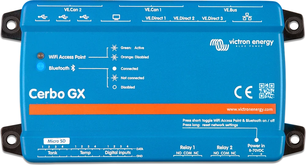
Other relays can also be controlled from Node-RED, but each must first be changed: in BMV set the relay option to REM (in VictronConnect), in Lynx Shunt VE.Can set the function to “Manual control” (in the GX menu), in larger MPPT controllers and RS series devices use manual mode (in VictronConnect). The Lynx Smart BMS relay cannot be controlled from Node-RED. You also cannot control the alarm relay or the AC-out 2 contactor in MultiPlus and Quattro.
Want to start a generator? GX has a built-in automatic generator start and stop function by relay, with its own start conditions (in the GX manual, chapter “Generator auto start/stop”), and Node-RED is not needed. The Victron generator example below does not control the relay directly, it uses the Generator node.
How this flow works
- Battery (input)State of charge from the battery monitor — on every change, and without “only changes” also every 5 s.
- hysteresis (function)SoC ≤ 30% → 1, SoC ≥ 50% → 0, unchanged in between. Sends only state changes.
- Relay (output)1 closes, 0 opens relay 1 in Cerbo GX (/Relay/0/State).
- debugShows every value sent to the relay in the Debug panel.
Step-by-step build
- New tab. In the Node-RED editor, add a new flow tab (the “+” button above the workspace) so the example does not get mixed up with other flows.
- Battery node. From the Victron nodes section in the palette, drag in the Battery input node. In its settings, choose your battery monitor and the “State of charge (%)” measurement. Leave the “only changes” field empty — then the node sends SoC on every change and additionally every 5 seconds, so the function gets a value quickly after a restart too.
- Function node. Add a standard function node, name it “hysteresis”, and paste in the code from the “Hysteresis code” section. Connect the Battery node output to the function input.
- Relay node. Add an output Relay node, choose “Venus device” and “Venus relay 1 state” (path
/Relay/0/State— numbering in the path starts at 0, so index 0 is relay 1). The node sets whatever it receives inmsg.payload: 0 — Open, 1 — Closed. Connect the function output to it. - Debug node. Also connect a debug node to the function output. You will see the values in the Debug panel on the right-hand side of the editor, and under the “hysteresis” node — the current SoC and relay state.
- Deploy and test. Click Deploy. To avoid waiting for the battery to discharge, temporarily add an inject node with a numeric value (type “number”, e.g. 25, then 55) connected to the function and check whether the relay in the Relays menu switches over. Then remove the inject node and click Deploy again.
Hysteresis code
If the relay were to switch on and off at a single threshold, for example 40%, then with SoC fluctuating around that value it would keep switching back and forth. Hysteresis separates those thresholds: the relay closes at 30% or below, and opens only at 50% or above. In between, it stays in the previous state. The function remembers this state in the node context and sends a message only when it changes, so the same value does not reach the relay every 5 seconds.
// Hysteresis: close the relay at SoC <= 30 %, open at SoC >= 50 %.
// Thresholds are examples - set your own.
const PROG_ZAL = 30;
const PROG_WYL = 50;

const soc = msg.payload;
if (typeof soc !== 'number' || isNaN(soc)) return null;  // no reading: do nothing

const poprzedni = context.get('stan');
let stan = (poprzedni === undefined) ? 0 : poprzedni;
if (soc <= PROG_ZAL) stan = 1;       // 1 = Closed
else if (soc >= PROG_WYL) stan = 0;  // 0 = Open
// between thresholds the state does not change

node.status({fill: stan ? 'green' : 'grey', shape: 'dot',
             text: 'SoC ' + soc.toFixed(1) + ' %, relay ' + (stan ? 'closed' : 'open')});

if (stan === poprzedni) return null;  // send only changes
context.set('stan', stan);
msg.payload = stan;
return msg;| SoC | What the function does | Relay |
|---|---|---|
| 60% | first reading, 50% or more → sends 0 | open |
| 40% | between thresholds — sends nothing | open |
| 30% | 30% or less → sends 1 | closed |
| 45% | between thresholds — sends nothing | closed |
| 50% | 50% or more → sends 0 | open |
- Reverse logic. Do you want to disconnect a load at low SoC rather than switch it on? Swap 1 and 0 in the two threshold lines in the code, or connect the circuit to the relay’s second contact — NC instead of NO.
- No reading. If
msg.payloadis not a number (for example, the battery monitor disappears), the function sends nothing and the relay stays in its current state. - After a restart. By default, the node context is stored in the GX device’s RAM and is lost on restart or power failure. The first reading after a restart always sets the relay: with SoC between the thresholds, to 0 (open) — even if it was closed before the restart. How to preserve the context is described in the “What to watch out for” section.
Ready flow to import
The same flow in JSON format. The Victron nodes are built as in the examples in the node-red-contrib-victron palette documentation.
- Copy the entire block below, including the
[and]brackets. - Import. In the editor, open the menu (button in the top-right corner) → Import, or press Ctrl-I, paste the text and click Import. The flow will appear in a new tab, “Relay by SoC”.
- Select your battery monitor. Open the “Battery SoC” node and choose your battery monitor and “State of charge (%)” from the list.
- Check the relay in the “GX Relay 1” node, change the thresholds in the function if needed, and click Deploy.
The Battery node points to the example SmartShunt from the Victron documentation (com.victronenergy.battery/277). The number at the end is different in every installation — it depends on the device and how it is connected. Until you select your battery monitor in the node, the function will not receive SoC and the relay will not switch.
[
{"id":"c24a5c0f10000001","type":"tab","label":"SoC relay with hysteresis","disabled":false,"info":"30/50% hysteresis - example from cpv24.pl"},
{"id":"c24a5c0f10000002","type":"victron-input-battery","z":"c24a5c0f10000001","service":"com.victronenergy.battery/277","path":"/Soc","serviceObj":{"service":"com.victronenergy.battery/277","name":"SmartShunt (example - choose your own)"},"pathObj":{"path":"/Soc","type":"float","name":"State of charge (%)"},"initial":"","name":"Battery SoC","onlyChanges":false,"x":150,"y":120,"wires":[["c24a5c0f10000003"]]},
{"id":"c24a5c0f10000003","type":"function","z":"c24a5c0f10000001","name":"hysteresis","func":"// Hysteresis: close the relay at SoC <= 30 %, open it at SoC >= 50 %.\n// The thresholds are examples - set your own.\nconst PROG_ZAL = 30;\nconst PROG_WYL = 50;\n\nconst soc = msg.payload;\nif (typeof soc !== 'number' || isNaN(soc)) return null;  // no reading: do nothing\n\nconst poprzedni = context.get('stan');\nlet stan = (poprzedni === undefined) ? 0 : poprzedni;\nif (soc <= PROG_ZAL) stan = 1;       // 1 = Closed\nelse if (soc >= PROG_WYL) stan = 0;  // 0 = Open\n// between thresholds the state does not change\n\nnode.status({fill: stan ? 'green' : 'grey', shape: 'dot',\n             text: 'SoC ' + soc.toFixed(1) + ' %, relay ' + (stan ? 'closed' : 'open')});\n\nif (stan === poprzedni) return null;  // send only changes\ncontext.set('stan', stan);\nmsg.payload = stan;\nreturn msg;","outputs":1,"noerr":0,"initialize":"","finalize":"","libs":[],"x":370,"y":120,"wires":[["c24a5c0f10000004","c24a5c0f10000005"]]},
{"id":"c24a5c0f10000004","type":"victron-output-relay","z":"c24a5c0f10000001","service":"com.victronenergy.system/0","path":"/Relay/0/State","serviceObj":{"service":"com.victronenergy.system/0","name":"Venus device"},"pathObj":{"path":"/Relay/0/State","type":"enum","name":"Venus relay 1 state","enum":{"0":"Open","1":"Closed"},"writable":true},"initial":"","name":"Relay 1 GX","onlyChanges":true,"x":600,"y":120,"wires":[]},
{"id":"c24a5c0f10000005","type":"debug","z":"c24a5c0f10000001","name":"relay state","active":true,"tosidebar":true,"console":false,"tostatus":false,"complete":"payload","targetType":"msg","statusVal":"","statusType":"auto","x":610,"y":180,"wires":[]}
]
Victron built-in examples
The Victron palette has a built-in examples library: menu (top right) → Import → Examples → node-red-contrib-victron. The same flows are also on the palette wiki page, so you can browse them without the editor. Three are closest to this example:
| Example | What it does | How it differs from the flow on this page |
|---|---|---|
| Threshold Control | The output turns on when the input value rises above the ON threshold, and turns off when it falls below the OFF threshold. Before each switch it waits for the set delay (ON/OFF delay). The thresholds and manual control are on the dashboard. | It controls the same relay 1 (/Relay/0/State), but the input is battery voltage from the System node (/Dc/Battery/Voltage), not SoC, and it adds delays. It requires extra modules: node-red-dashboard, node-red-contrib-ui-led and node-red-contrib-countdown. |
| Run generator at certain time when SOC is below 50% | Every day at 18:00 it checks the stored SoC. If it is low, it starts the generator for 45 minutes: the trigger node sends 1, then 0 after 45 minutes. The SoC is stored in flow.SOC context by the change node. | It controls the Generator (Manual Start) node, not a relay. Note: the description says “below 50%”, but the switch node in this flow checks “less than or equal to 50” (name: “Start if SOC is <= 50%”). |
| Only messages at regular intervals | The change node saves the last value to context, and the inject node reads it at fixed intervals. | Useful when you need the latest value at a fixed rate, independent of when the input node sends it. |
Description of all Victron input and output nodes: Victron nodes in Node-RED.
What to watch out for
- Context after restart. To keep context across restarts, Victron describes in the FAQ the file
/data/home/nodered/.node-red/settings-user.jswith thecontextStoragesetting (modulelocalfilesystem, save every 300 s, that is every 5 minutes). When this is the default context store, the function code works without changes. Victron warns against saving too often, because it wears out flash memory. - Safe mode. If after changes the flow overloads the GX or behaves incorrectly, enable Node-RED in the GX menu in safe mode. Node-RED will start without running flows, you can fix them, and they will run again after you click Deploy.
- Restart Node-RED. From the GX menu: turn Node-RED off and on again in Venus OS Large Features → Node-RED.
- Time in the flow. In time-based examples, such as with a generator at 18:00, Node-RED uses the time zone set in Remote Console. After changing it, you must restart Node-RED.
A Node-RED flow does not replace a BMS, fuses or circuit breakers — after a GX restart or a flow error, the relay may remain in an unexpected state. The circuit connected to the relay must be safe in both states. Victron does not support installations that use Node-RED for advanced solutions.
Devices this applies to
Sources
- Venus OS Large image: Signal K and Node-RED — sections 2, 5.4 and 5.7, FAQ Q4, Q5, Q9 and Q11victronenergy.com · EN
- Cerbo GX manual — configuration, Settings → Integrations → Relaysvictronenergy.com · EN
- node-red-contrib-victron — Input nodes (Battery, /Soc)github.com · EN
- node-red-contrib-victron — Output nodes (Relay, /Relay/{relay}/State)github.com · EN
- node-red-contrib-victron — Example Flowsgithub.com · EN
Next: Node-RED on Cerbo GX — all articles · first start-up · Victron nodes · Cerbo GX