
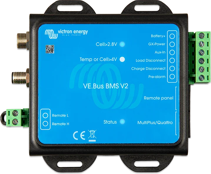
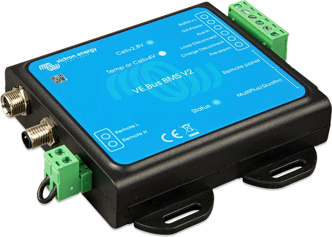
VE.Bus BMS V2 — terminal descriptions: Battery +, Aux in, Load Disconnect, Charge Disconnect, Pre-alarm, Remote L and H, and LEDs Cell<2.8 V and Temp or Cell>4 V
VE.Bus BMS V2
Victron Lithium Smart battery management system (12.8 V and 25.6 V) in systems with a VE.Bus inverter or inverter/charger — MultiPlus or Quattro. Based on battery signals, it switches off the inverter and charger via VE.Bus, and other chargers and loads via their control outputs.
- 12 / 24 / 48 V
- up to 20 batteries
- VE.Bus
- Load / Charge Disconnect
- Pre-alarm
Protection of each cell
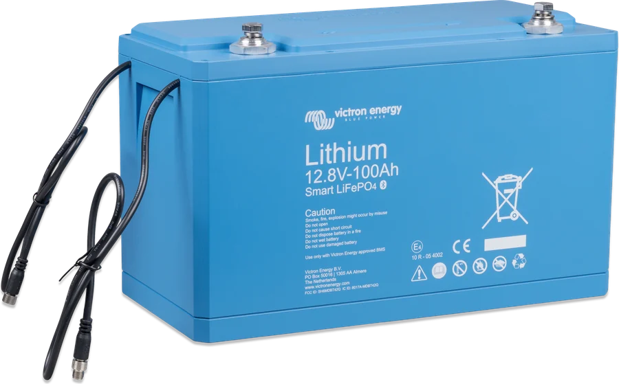
Lithium Smart batteries have a built-in BTV module (balancing, temperature and voltage measurement), but they do not disconnect charging or loads themselves. An external BMS does that. Smart LiFePO4 batteries (12.8 V and 25.6 V) may only be used with an external BMS approved by Victron — the battery itself does not disconnect charging or loads. Batteries are connected in a chain with BMS cables — the first and last cable to the BMS. Up to four 12.8 V batteries or two 25.6 V batteries in series; up to 20 batteries in total (up to 84 kWh in a 12 V system, up to 102 kWh in 24 and 48 V).
- up to four 12.8 V batteries or two 25.6 V batteries in series, up to 20 batteries in total,
- bank capacity up to 84 kWh in a 12 V system and up to 102 kWh in 24 and 48 V,
- it controls the inverter/charger directly via VE.Bus — no additional relays required.

| Battery condition | VE.Bus BMS V2 reaction |
|---|---|
| Cell voltage about to become too low | Pre-alarm (factory set to 3.1 V per cell, adjustable in the battery 2.85–3.15 V); at least 30 s before disconnecting loads. Pre-alarm is not passed to GX or VRM. |
| Cell voltage too low | Switches off the inverter (via VE.Bus) and loads (Load Disconnect output) |
| Cell overvoltage, too low temperature or too high temperature | Switches off or limits charging via VE.Bus, GX/DVCC or the Charge Disconnect output, depending on the charger type |
With a GX device: switching on, switching off and “charger only” mode for VE.Bus devices, and control of compatible solar charge controllers via DVCC — without an additional BatteryProtect or Cyrix-Li-Charge, as in the older VE.Bus BMS V1. GX/DVCC control requires Venus OS 2.80 or later and DVCC enabled. VE.Bus BMS V2 does not set these devices’ charging voltage, so the charge algorithm must be configured correctly in the devices.
What VE.Bus BMS V2 can do
VE.Bus control
The BMS switches off the inverter or inverter/charger directly via the VE.Bus communication bus — no relay or additional module is needed.
Load Disconnect
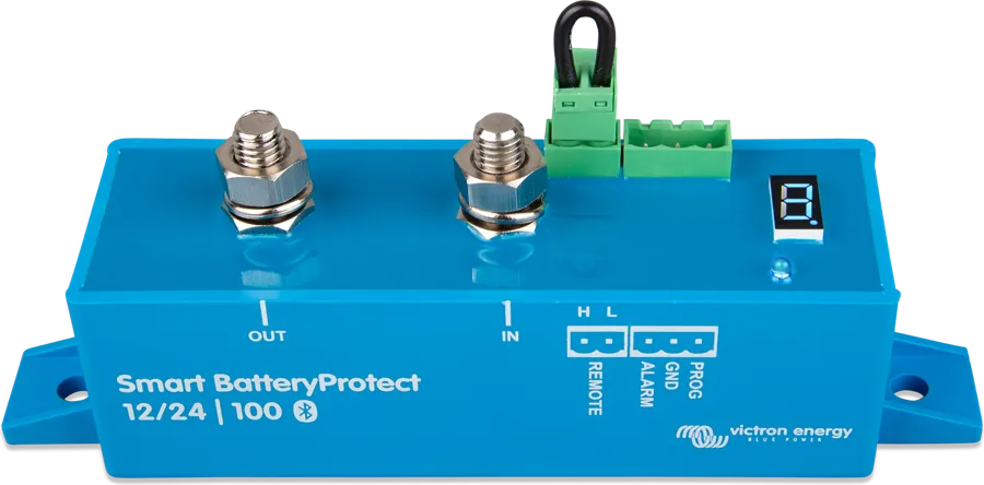
Normally high, floating when cell voltage is too low; load capacity up to 1 A. For loads, the manufacturer recommends Smart BatteryProtect in Li-ion mode because of the low current draw.
Charge Disconnect
Normally high, floating when a cell overvoltage or wrong temperature occurs; load capacity only 10 mA — for charger remote inputs and Cyrix-Li relays.
Pre-alarm in advance
Turns on at least 30 seconds before disconnecting loads, factory set at 3.1 V per cell (adjustable in the battery 2.85–3.15 V). It is not passed to the GX device or VRM.
GX and DVCC integration
With a GX device it also controls compatible solar charge controllers via DVCC (Venus OS 2.80 or later). It does not set charging voltages, however — you must configure the algorithm in the devices themselves.
Power supply for the GX device
The GX-Pow output powers the GX device from the battery, and the Aux-In input lets you power it from another source — so remote access works even when the system is switched off.
Remote panel port
Accepts a GX device, Digital Multi Control panel and VE.Bus Smart dongle — including together. When a DMC panel is in the system, mode switching stays with it.
System switch
The Remote L and H terminals switch everything off: both control outputs become floating, so chargers and loads stop.
Controls
| Output | Normal state | What it is for |
|---|---|---|
| Load Disconnect | high; floating when cell voltage is too low (capacity up to 1 A) | load remote input or Smart BatteryProtect in Li-ion mode (recommended — low current draw) |
| Charge Disconnect | high; floating when there is cell overvoltage, too low or too high temperature (up to 10 mA) | AC charger remote input, DC-DC charger, solar charge controller; Cyrix-Li-Charge or Cyrix-Li-ct relay |
| Pre-alarm | floating; high when cell voltage is about to become too low (up to 1 A, no short-circuit protection) | buzzer, lamp |
| GX-Pow (output) and Aux-In (input) | — | power supply for the GX device from the battery or from Aux-In (higher voltage) — the power supply on Aux-In will keep the GX device and remote access running after the system is switched off |
| Remote L / H | — | system switch; after switching off, both control outputs become floating |
Check the loads’ residual current in the switched-off state. After disconnection due to low battery voltage, about 1 Ah remains per 100 Ah of capacity; a small residual current can damage a discharged battery.
“Remote panel” port: GX device, Digital Multi Control panel and VE.Bus Smart dongle (also together). If a Digital Multi Control is used in a system together with a GX device or VE.Bus Smart dongle, control of inverter/charger on, off and “charger only” mode is possible only via the Digital Multi Control. LEDs: blue “status” flashes every 10 s when data are sent to the MultiPlus; red “>4 V” — charging cut off because of overvoltage or temperature; blue “>2,8 V” — loads on, cell voltage above 2.8 V. Fast flashing of the “status” LED — BMS in bootloader mode (for example after an interrupted update — repeat it in VictronConnect or via VRM).
How to connect VE.Bus BMS V2
The BMS protects the Lithium Smart battery: it switches off the inverter and charger via VE.Bus, and the other devices via the control outputs. It must remain connected to the battery positive. Simplified diagram.
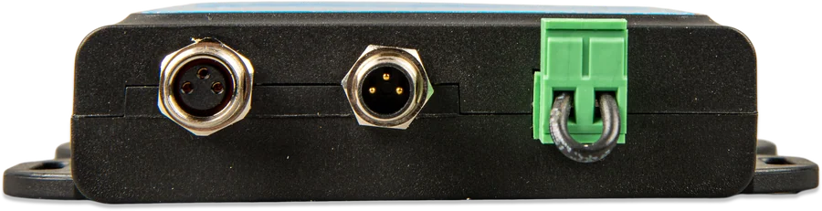
- BMS battery cablesChain; first and last cable to the BMS.
- Battery+ via 1 A fuseThe BMS must be connected to the battery positive.
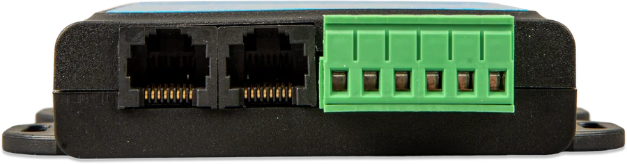
- RJ45 to the MultiPlus“MultiPlus/Quattro” port; in a parallel system, only the main unit.
- GX device“Remote panel” port; with DVCC it also controls solar charge controllers.
- Control outputsLoad Disconnect → loads, Charge Disconnect → chargers.
Basic connection
Installation may be carried out only by a qualified and trained installer. Before changing any connection, switch off the system and check that no dangerous voltages are present.
- BMS battery cables to the BMS (with several batteries — chain connection, M8 extension leads if needed).
- DC cables from the MultiPlus to the battery; update its firmware (below).
- Battery positive through a 1 A fused cable to the BMS “Battery+” terminal — the cable is not included: at least 0.75 mm².
- Connect the MultiPlus VE.Bus port to the BMS “MultiPlus/Quattro” port with the supplied RJ45 cable.
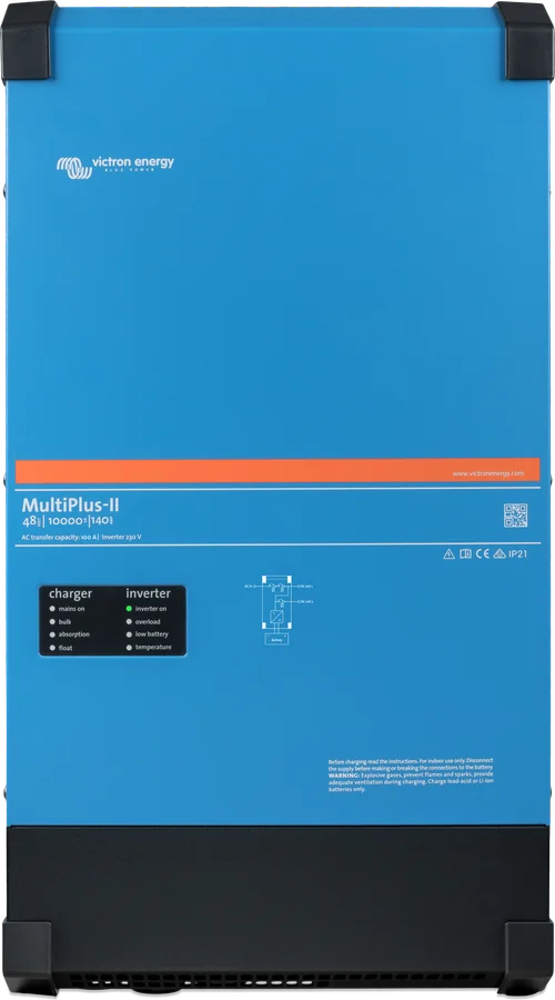
- The grid detector (included) is used in older models that require this add-on, including the relevant MultiPlus and Quattro models. In the MultiPlus, one pair of AC wires is used, and in the Quattro both pairs. It is not needed in the new MultiPlus 12/1600/70 and 12/2000/80, MultiPlus-II, Quattro-II and inverters. In parallel, three-phase or split-phase systems, connect it only in the master/leader unit. Its job: to start the inverter/charger when AC supply appears after the BMS has switched it off because of low cell voltage.
The BMS must remain connected to the battery positive — only then will it keep the MultiPlus in low-power mode even when AC supply is present (the MultiPlus stops working as an inverter and charger, closes the transfer relay and indicates low battery voltage).
Requirements for the MultiPlus and Quattro
- VE.Bus firmware of all inverters and inverter/chargers in the system: xxxx489 or newer.
- Versions from xxxx415, lower than xxxx489: you must install the VE.Bus BMS or ESS Assistant.
- Below xxxx415: VE.Bus error 15 will appear; if an update is not possible, VE.Bus BMS V2 cannot be used.
- Devices with a processor marked 19xxxxx or 20xxxxx are not supported — the older VE.Bus BMS is intended for them.
VE.Bus BMS V2, Lynx Smart BMS or NG versions
VE.Bus BMS V2
For systems with a VE.Bus inverter or inverter/charger and Lithium Smart batteries. Battery current does not flow through the BMS — it controls via signals only.
up to 20 batteries · 12/24/48 VLynx Smart BMS
BMS in a Lynx bus system: safety contactor, built-in battery monitor and control via ATC/ATD contacts and VE.Can. Lynx Smart BMS datasheet.
contactor + monitor“NG” versions
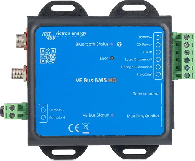
Lithium NG batteries require BMS units marked NG: VE.Bus BMS NG, smallBMS NG or Lynx Smart BMS NG.
for NG batteries onlyVE.Bus BMS V2 is intended for systems with a VE.Bus inverter or inverter/charger and controls the other devices by signals only — battery current does not flow through the BMS. Lynx Smart BMS is a BMS in a Lynx distribution system with a built-in battery monitor and safety contactor, controlled via ATC/ATD contacts and VE.Can. For Lithium NG batteries, the “NG” versions are intended (VE.Bus BMS NG, smallBMS NG, Lynx Smart BMS NG).
Frequently asked questions about VE.Bus BMS V2
Which batteries is it intended for?
For Victron Lithium Smart 12.8 V and 25.6 V batteries. Up to four 12.8 V batteries or two 25.6 V batteries can be connected in series, and up to 20 batteries in total — up to 84 kWh in a 12 V system and up to 102 kWh in 24 and 48 V.
How does it differ from VE.Bus BMS V1?
With a GX device and DVCC enabled (Venus OS 2.80 or newer), it also controls compatible solar charge controllers — without the additional BatteryProtect or Cyrix-Li-Charge, as in version V1.
How much current can the control outputs handle?
Load Disconnect up to 1 A, Charge Disconnect up to 10 mA, pre-alarm up to 1 A — all without short-circuit protection. For loads, it is best to use Smart BatteryProtect in Li-ion mode because it draws little current.
Why must the BMS be connected to the battery positive?
Only then will it keep the MultiPlus in low-power mode, even when AC supply is present. The positive is connected with at least 0.75 mm² cable and a 1 A fuse to the “Battery+” terminal.
What remains in the battery after disconnection due to low voltage?
About 1 Ah for every 100 Ah of capacity. That is why you must check the residual current of the loads — a small draw can damage a discharged battery.
What firmware must the MultiPlus or Quattro have?
VE.Bus version xxxx489 or newer. Between xxxx415 and xxxx489, you must install the VE.Bus BMS or ESS Assistant. Below xxxx415, VE.Bus error 15 will appear, and this BMS does not support devices with 19xxxxx and 20xxxxx processors — the older VE.Bus BMS is intended for them.
What is the grid detector supplied with?
It starts the inverter/charger when AC supply appears after the BMS has switched it off because of low cell voltage. Older models need it; it is not required in the MultiPlus 12/1600/70 and 12/2000/80, MultiPlus-II, Quattro-II or inverters. In parallel and three-phase systems, connect it only in the master unit.
What do the LEDs on the enclosure mean?
Blue “status” flashes every 10 seconds when the BMS sends data to the inverter. Red “>4 V” means charging is cut off because of overvoltage or temperature, and blue “>2,8 V” means the loads are on. Fast flashing of the “status” LED means bootloader mode, for example after an interrupted update — repeat it in VictronConnect or via VRM.
Does the BMS set the charging voltages?
No. It only controls charge on/off, so you must set the algorithm and voltages correctly in the chargers and controllers themselves.
Manufacturer documentation
Content checked against Victron Energy documentation (datasheets and manuals) — as of 19 September 2026. Report a content error · Revision log