
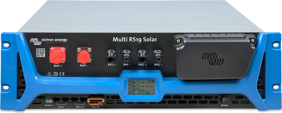
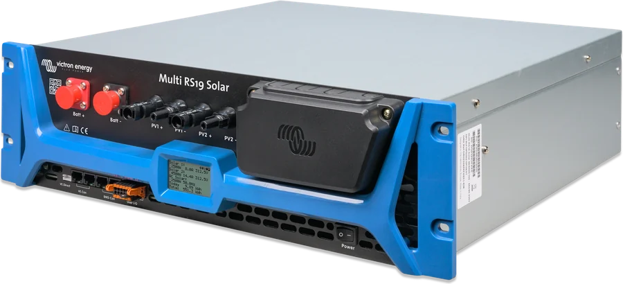
Multi RS19 Solar — front panel with display, switch and connectors
Multi RS19 Solar
48 V inverter/charger and two 3 kW MPPT controllers in a 19" housing for a standard rack cabinet — alongside 19" batteries from different manufacturers. Electrically, it is the Multi RS Solar family: 6 kVA, two 450 V trackers and charging up to 100 A.
- 48 V
- 230 V · 6 kVA
- 2 × 450 V MPPT
- 19" · 12.2 kg
- VE.Can · BMS-Can
Multi RS Solar for a rack cabinet
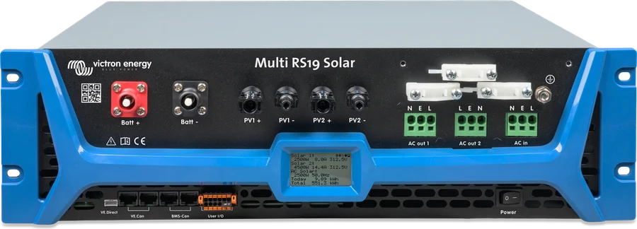
Multi RS19 Solar is a 6 kW inverter/charger with two 3 kW MPPT trackers in a 19" enclosure. It is installed horizontally in a standard rack cabinet, together with 19" batteries — all connections, including the batteries and solar panels, are on the front panel.
The datasheet describes four modes: hybrid (PV surplus to the batteries, used at night), backup (switch to battery when the grid fails), off-grid and generator support (limiting generator runtime and adding power from the battery).
- 48 V battery galvanically isolated from the AC terminals and from the PV field,
- two independent trackers up to 450 V — two strings of panels, for example on two roof sections,
- three units (one per phase) form a three-phase system.
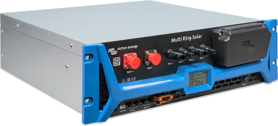

What Multi RS19 Solar can do
6 kVA inverter
Continuous current 25 A AC. Peak 9 kW for 3 s and 7 kW for 4 minutes (cold unit). With power from the MPPT, continuous power rises by about 10%, to 5800 W.
Two 450 V MPPTs
Two independent 3 kW trackers (6 kW in total), start at 120 V, operating range 65–450 V, 12 A operating and 16 A short-circuit current per tracker.
100 A charger
From the grid or generator up to 88 A (at 230 V and 57.6 V), together with PV up to 100 A. Battery temperature sensor included.
PowerControl and PowerAssist
Grid or generator current limit — charging only from surplus. When the input is not enough, the battery makes up the missing power.
Two AC outputs
AC-out-1 uninterrupted. AC-out-2 permanently connected to the AC input — for non-critical loads; taken into account by PowerControl.
ESS and grid codes
Grid-connected energy storage: self-consumption or keeping the battery charged. Export to the grid after selecting the grid code.
VE.Can, BMS-Can, Bluetooth
GX via VE.Can, VE.Direct to GlobalLink 520, BMS-Can for small systems without GX, configuration in VictronConnect.
Relay and AUX inputs
Potential-free relay 4 A up to 35 V DC and 1 A at 70 V DC — including alarm and generator control; not for 230 V circuits. Two AUX inputs, for example export lock-out.
Three phases
Maximum three units, one per phase, connected via VE.Can — star (Y) only. Parallel operation is not available.
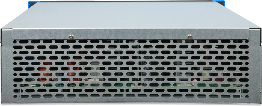
Main specifications
| Inverter and AC | |
|---|---|
| Battery voltage | 38–62 V DC (start at 41 V, disconnect at 65.5 V) |
| Output | 230 V ±2%, 50 Hz ±0.1% (240 V and 60 Hz possible) |
| Continuous power | 25 °C: 4,800 W at 46 V → 5,300 W at 52 V; 40 °C: 4,500 W; 65 °C: 3,000 W |
| Peak power | 9 kW for 3 s, 7 kW for 4 min |
| AC input and switch | 50 A, 187–265 V, 45–65 Hz |
| Efficiency | 96.5% at 1 kW, 94% at 5 kW |
| No-load consumption | 20 W |
| Low battery voltage | shutdown 37.2 V, restart 43.6 V (adjustable) |
| PV and charger | |
|---|---|
| PV voltage | Voc max. 450 V, start 120 V, MPPT 65–450 V |
| PV current per tracker | 12 A operating, 16 A short-circuit |
| PV power | 3 kW per tracker, 6 kW total |
| PV insulation | pre-start test, 100 kΩ threshold; 30 mA leakage |
| Charging from AC | 88 A at 57.6 V (230 V, 25 °C); up to 5000 W |
| Total charging | 100 A DC (AC + PV) |
| Absorption / float | factory default 57.6 / 55.2 V, range 36–60 V |
- Enclosure
- steel, 19", 133 × 483 × 430 mm, 12.2 kg
- Ingress protection
- IP20, protection class I
- Operating temperature
- −40 to +65 °C, fan cooling
- Grid system
- TN and TT only
- Battery
- Amphenol SurLok Plus 5.7 mm, 120 A
- AC
- spring terminals 10 mm² solid / 6 mm² stranded
- Communication
- VE.Can, BMS-Can, VE.Direct, Bluetooth
- Product code
- PMN482602000
The table in the manual gives continuous power at 25 °C as 4600–5200 W, while the datasheet gives 4800–5300 W. We have adopted the datasheet values. The datasheet and the manual table specify a maximum output overcurrent protection of 30 A, while the UPS specification and section 3.8 of the manual specify an external circuit breaker up to 50 A on the input and output; the sources do not explain how these values relate to each other.
Where the Multi RS19 Solar sits in the system
Two strings of panels on two trackers, grid or generator on the AC input, 48 V battery through a fuse. Hover over or touch a diagram element. Simplified diagram.
- PV → 2 trackersOne string per tracker, Voc < 450 V and < 8 × float.
- Grid → AC-inUp to 50 A, TN or TT grid.
- AC-out-1Loads also powered from the battery.
- AC-out-2Only when powered from an external source.
- Battery → fuse25 mm² and 125 A for cables up to 2 m.
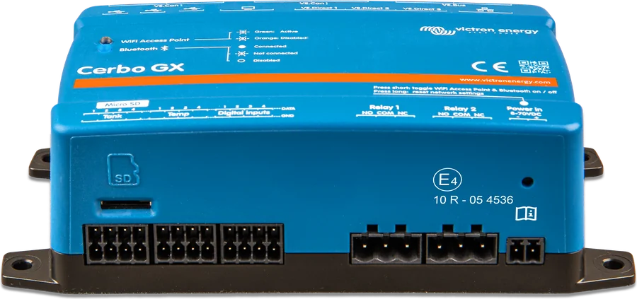
- GX (VE.Can)Monitoring, VRM and DVCC.
PV connection rules
The open-circuit voltage of the array must be lower than eight times the battery float voltage — at a float voltage of 54.0 V this is 432 V. If you exceed this, the unit reports error 29 (“Over-charge Protection”) and shuts down. Solution: higher float voltage or fewer panels in the string.
- Maximum 450 V — overvoltage damages the unit and is not covered by the warranty. In winter Voc rises: the manufacturer recommends an MPPT calculator and about 10% margin.
- One array to one input — do not connect one array to both trackers. The array may be oversized above 3 kW; the tracker will limit the power.
- Only original Stäubli MC4 connectors. A reverse-connected array with short-circuit current above 16 A voids the warranty.
- Class A modules according to IEC 61730, without optimisers; mixing different panel types is not recommended. PV+ and PV− isolated from earth, frames earthed.
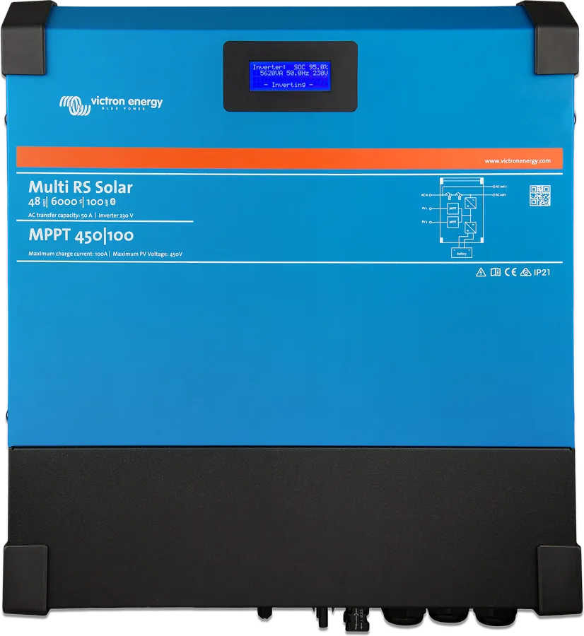
RS19 or wall-mounted Multi RS Solar?
| Multi RS19 Solar | Multi RS Solar | |
|---|---|---|
| Installation | horizontal in a 19" cabinet, 1U above and below | vertical on the wall |
| Dimensions / weight | 133 × 483 × 430 mm, 12.2 kg | 462 × 425 × 127 mm, 12.3 kg |
| Ingress protection | IP20 | IP21 |
| Battery | Amphenol SurLok Plus, 25 mm², 125 A | M8 screws |
| Inverter, PV, charger | common: 25 A AC, 2 × MPPT 450 V, 88 A from AC, 100 A total (continuous power at 25 °C the RS19 datasheet gives as 4800–5300 W, the wall-mounted version datasheet as 4600–5200 W) | |
Multi RS19 Solar
For a rack cabinet with 19" batteries — when the system is to stand in one place, with short DC cables.
48 V · 19" · 2 × MPPTMulti RS
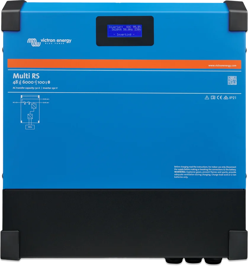
The same inverter and mains charger parameters, but without built-in MPPTs — PV via separate controllers or a PV inverter. Multi RS datasheet.
48 V · 6 kVAMulti HS19 Solar
A single three-phase 15 kW unit with four MPPTs and a 650–1000 V battery, also in a 19" enclosure. Multi HS19 Solar datasheet.
3 phase · 15 kWCabinet, battery and connection order
There may be 400–500 V DC inside even after switching off. Disconnect all sources and wait at least 5 minutes. Cover the panels during installation. Installation only under the supervision of a qualified installer.
The enclosure must be earthed: the enclosure earth terminal is connected to the general earth with a conductor cross-section at least the same as the PV cables.
For cables up to 2 m: 25 mm² and 125 A fuse. Fit the main fuse only after all DC connections are made; Amphenol plugs must not be connected or disconnected under voltage. Reverse battery polarity destroys the unit — no warranty.
- Order: 1) battery after checking polarity with a multimeter (minus first, then plus, plug until it clicks), 2) remote, relay and communication, 3) PV array after checking polarity.
- Cabinet: horizontal, 1U free above and below, free air flow from front to back, non-combustible surroundings. Never directly above lead-acid batteries.
- DC cables: flexible class 5 copper stranded cable (strands max. 0.4 mm), insulation min. 90 °C, as short as possible — voltage drop above 2.5% is not acceptable. Batteries with HB flammability class or better.
- AC: spring terminals, insulation stripped back 15 mm; circuit breaker up to 50 A on input and output; do not swap L and N. There must be an isolator on both the AC and DC sides.
The earthing relay connects N to the enclosure when no external AC is present. There is no full galvanic isolation between the PV input and the AC terminals — the internal RCMU module shuts the inverter down when it detects residual current. Residual-current protection is selected according to local regulations; the manufacturer describes it in the “RCD Information on Multi RS” document. More: earthing and RCD.
How to set it up
Configuration only in VictronConnect — there are no VEConfigure assistants. Bluetooth is enabled by default (PIN 000000 or from the sticker; a lost PIN resets the code with PUK). On Windows you need a VE.Direct–USB interface.
- Battery: presets Normal, High, LiFePO4 2-wire BMS and User defined. For LiFePO4, charging is blocked below 5 °C (with sensor).
- BMS: Lynx Smart BMS always via VE.Can; smallBMS NG via the allow-to-charge and allow-to-discharge contacts (Remote mode “2-wire BMS”). The BMS-Can port is only for small systems without GX with one device.
- DVCC only through a GX device — the unit itself does not have these settings.
- ESS: modes with BatteryLife (lead-acid), without BatteryLife (lithium), Keep batteries charged (default and for off-grid), External control and PV inverter only — operation without batteries as a PV inverter, only with a grid code and the operator’s approval, with no loads and no PV inverters on AC-out-1.
- Grid code is factory-set to “None”; after the first setting, changes are only possible with a password; a country’s presence in the list does not mean certification. Energy meter: only the Victron VM-3P75CT in the “Grid” role (VE.Can or Ethernet — GX from v3.70 and Multi from firmware v1.26).
- Generator (firmware from v1.11): input type Generator, “Moderate generator load changes” enabled, “Energy meter support” disabled, current limit matched to generator power, UPS function disabled. Without a grid code — “None”; with a grid code — “no LOM detection” and “Feed-in allowed” disabled. ESS mode: Keep batteries charged. Never disable LOM when connected to the grid.
Three-phase (firmware from v1.13): maximum three units, one per phase, connected via VE.Can with terminators, star only. Each unit has separate AC and DC protection of the same type and a common battery bank. Do not enable “Continue with missing phase” with three-phase loads, for example motors. If you frequently disconnect from the grid in 3-phase systems or with a generator, disable UPS function.
What the Multi RS19 Solar does not do
The manual’s “Limitations” section and notes from other sections. The manufacturer states that limitations may change with firmware updates — before buying, it is worth checking whether the unit is suitable for the application.
No parallel operation
One unit operates per phase. The manual does not state whether current hardware will receive this function in firmware.
No VEConfigure assistants
Only what is in VictronConnect — without the advanced controls known from VE.Bus devices.
ESS not fully
Not all grid codes are available — check the current certifications for Poland.
AC charging up to 5000 W
At 230 V; in practice less, when the unit is warm or airflow is poor. Combined with PV, up to 100 A.
Limit after 4 minutes
After about 4 minutes of heavy load, inverter current is limited to 25 A AC.
AC-out-2 without control
The output is permanently connected to the AC input — it cannot be programmed or controlled by a relay.
Without VE.Smart Networking
The unit does not work with the VE.Smart network, for example with Smart Battery Sense.
PV inverter on AC — up to about 95%
A PV inverter on the output (up to 5000 W, frequency-controlled) will charge the battery only to about 95% — an MPPT is needed for a full charge.
No split-phase and delta
Only one phase or three phases in star.
Most common faults
Typical situations described in the manual. You can check the error number from the display or VictronConnect in the RS device error codes section — the Multi RS19 Solar uses the same numbering as MPPT charge controllers and other RS devices.
The device does not switch on
Check the REMOTE_H–REMOTE_L bridge on the User I/O terminal block (fitted by default) and the switch in the On position. In “2-wire BMS” mode, with the terminals open the unit will not turn on; with the bridge fitted — it will turn on without charging.
MPPT does not start
The tracker starts at a PV voltage of 120 V, and continues running from 65 V. Check cables, fuses and PV switches, weather, shading.
No charging from PV, unit warm
This is how a string of panels connected the wrong way round behaves — there is no error code for it, and the PV voltage is close to zero. Measurements on PV only with insulated MC4 probes.
Shuts down under heavy load
Overload: after three restarts within 30 s, the unit shuts down. Disconnect some loads, switch them off and on again.
Shuts down on low battery
After three cycles it stops trying — switch off and on again, reduce the load. With an empty battery and an allow-to-charge signal, temporarily disable this function.
Overtemperature
Restart after 30 s, with no permanent shutdown. Check airflow in the cabinet (front to back) and 1U spacing above and below the unit.
Battery does not charge
Full battery, settings too low, external control (ESS, DVCC), temperature or reverse PV polarity.
Battery not fully charged
Too few panels, load too high, voltage drop on the cables above 2.5% or incorrect temperature compensation.
Frequent disconnection from the grid
In a three-phase system or with a generator, disable UPS function — in three phases it can be too sensitive.
Frequently asked questions about Multi RS19 Solar
How does the Multi RS19 Solar differ from the Multi RS Solar?
The enclosure and connectors: the RS19 is mounted horizontally in a 19" cabinet (133 × 483 × 430 mm, IP20), the battery is connected with Amphenol SurLok Plus plugs and it has a BMS-Can port. The inverter current, two 450 V MPPTs and the charger have the same specifications; the RS19 datasheet gives a slightly higher continuous power at 25 °C. Multi RS Solar datasheet.
Which cable and fuse do you need for the battery?
For cable lengths up to 2 m, the manual specifies 25 mm² and a 125 A fuse; the SurLok Plus plugs are for 25 mm² cable. A voltage drop on the cables above 2.5% is not allowed.
How many panels can I connect?
Two strings, one per tracker, up to 3 kW each (the array can be oversized). String Voc below 450 V and below 8 × the battery float voltage; operating current up to 12 A, short-circuit current up to 16 A per tracker.
Can I connect two units in parallel?
No. You can build a three-phase system from three units (one per phase), but there is no parallel operation on a single phase.
How do I connect a battery with a BMS?
With a GX device — connect the battery BMS to the GX BMS-Can port, and the Multi RS19 via VE.Can. The unit’s own BMS-Can port (500 kbit/s, CAN-bus BMS LV protocol) is only for small systems without GX with one device. Lynx Smart BMS always via VE.Can.
Can I use it with a generator?
Yes, from firmware v1.11: input type Generator, “Moderate generator load changes” enabled, “Energy meter support” disabled, current limit matched to the generator and UPS function disabled. ESS mode remains on Keep batteries charged, and when a grid code is set, feed-in and LOM detection are disabled (never when connected to the grid).
The unit does not switch on — what should I check?
The bridge between REMOTE_H and REMOTE_L on the User I/O terminal block (fitted by default), the position of the physical switch (On) and the Remote mode — in “2-wire BMS” mode, with the terminals open the unit will not turn on, and with the bridge fitted it will turn on without charging.
Does it work with a third-party PV inverter?
Yes, on the AC output up to 5000 W, if the PV inverter responds to frequency changes — the Multi limits it by shifting the frequency when the grid is disconnected (fstop 53.2 Hz). The 1:1 rule and the minimum battery size from the AC Coupling manual apply (required reading); the setup has been tested with Fronius inverters (MG50/60). This will charge the battery to about 95%.
Manufacturer documentation
Discrepancies in the documents: continuous power at 25 °C (datasheet 4,800–5,300 W, manual table 4,600–5,200 W), AC terminal cross-section (datasheet and manual table 10 mm² solid wire / 6 mm² stranded, manual section 3.8 max. 6 mm²), output protection (datasheet and manual table 30 A, UPS specification and section 3.8 — 50 A), I/O ports (datasheet and table: 2 analogue-digital, section 3.12.5: 2 AUX digital inputs) and AC-out-2 delay (the manual gives both “no delay” and about 2 minutes).
Content checked against Victron Energy documentation (datasheets and manuals) — as of 22 September 2026. Report a content error · Revision log