
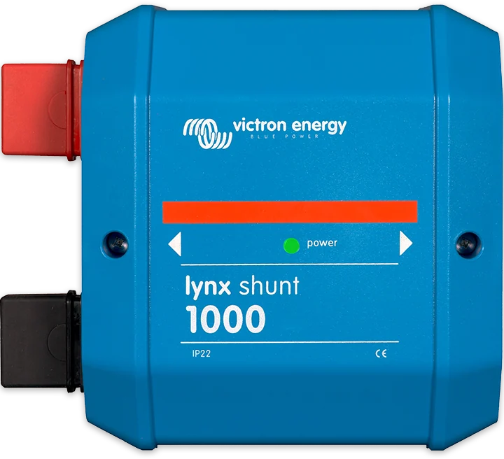
Lynx Shunt VE.Can 1000 — module with shunt and power LED
Lynx Shunt VE.Can
A Lynx system module combining three functions: positive and negative busbars, battery monitor and main fuse holder. It communicates with the GX device via VE.Can — showing state of charge, current, voltage, alarms and history.
- 1000 A continuous
- 12 / 24 / 48 V
- M8 or M10
- VE.Can
- relay, temperature sensor
Three things in one enclosure
The Lynx Shunt VE.Can is a Lynx bus system module that combines positive and negative busbars, a battery monitor and a main fuse holder. Instead of a separate shunt, fuse holder and busbars, you install one module.
Current is measured by the shunt built into the negative busbar — so all negative connections for loads and chargers must pass through the system side. Data goes via VE.Can to the GX device: that is where you see state of charge, current, voltage, alarms and history, and where you set the parameters.
- 1000 A continuous current, which is 12, 24 or 48 kW depending on system voltage,
- 8 × 30 mm tinned copper busbar and main fuse inside the module,
- 3 A alarm relay and battery temperature sensor input.

What the Lynx Shunt VE.Can can do
Battery monitor
State of charge, current, voltage and history — all visible on the GX device screen and in the VRM portal. Battery capacity is set manually: factory default 200 Ah, from firmware 4.19 up to 32,500 Ah.
Main fuse in the module
Fuse holder for CNN fuse (also ANL and MEGA in the M10 version), bought separately — available ratings from 35 to 800 A. A blown fuse is indicated by an alarm.
1000 A busbars
8 × 30 mm tinned copper, 1000 A continuous current — 12 kW at 12 V, 24 kW at 24 V and 48 kW at 48 V. The module latches to the rest of the Lynx system.
VE.Can and NMEA 2000
Two RJ45 sockets with terminators included; the GX port profile is “VE.Can & Lynx Ion BMS (250 kbit/s)”. With a VE.Can–NMEA 2000 cable, the data also goes to the chartplotter.
Alarm relay
3 A / 30 V DC relay, programmable from GX: generator start and stop by state of charge or voltage, blown fuse indication, voltage and temperature alarms.
Temperature sensor
On screw terminals, polarity-sensitive: black wire to minus, red wire to plus. Battery temperature is used for alarms and charge compensation.
SoC calculation parameters
The “charged” voltage is set 0.2–0.3 V below the charger float voltage, tail current is 4% by default, charged detection time is 3 minutes, Peukert exponent is 1.25. Lithium batteries require their own settings.
System power supply
The module powers the GX device and Lynx Distributor with an RJ10 cable. Self-consumption is 60 mA at 12 V, 33 mA at 24 V and 20 mA at 48 V; operating range −40…+60 °C.
M8 or M10
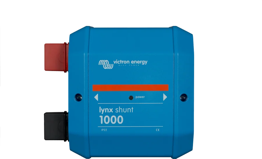
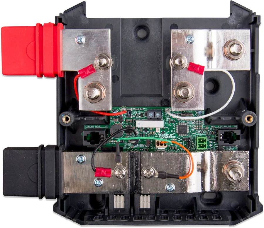

| Lynx Shunt VE.Can M8 | Lynx Shunt VE.Can M10 | |
|---|---|---|
| Busbars between modules | M8 | M10 |
| Main fuse | CNN, M8 mounting | CNN, ANL or MEGA (MEGA on M6 studs), M8 mounting |
| Busbar instead of fuse | no | yes, included — the main fuse can then be outside the module |
| VE.Can | RJ45, two terminators included | RJ45, two terminators included |
Common: 9–70 V DC supply (12, 24, 48 V systems), 1,000 A continuous (12 / 24 / 48 kW), 8 × 30 mm tinned copper busbar, Lynx Distributor powered by RJ10 cable, temperature sensor and relay on screw terminals, ABS enclosure 190 × 180 × 80 mm, 1.4 kg, IP22. The fuse is bought separately; its type, current and voltage rating are selected to suit the maximum current and voltage of the protected circuit. Victron offers, for example, CNN 325 A / 80 V. Available ratings range from 35 to 800 A. M8 and M10 modules are not connected directly to each other.
How to connect Lynx Shunt VE.Can
The module combines three things: the positive and negative busbars, a battery monitor and the main fuse holder. All negative leads from loads and chargers must pass through the system side — otherwise the state-of-charge reading will be too high. Simplified diagram.
- Disconnect the battery positivesNever work on live busbars.
- Batteries and systemBatteries on the battery side, loads and chargers on the system side — all negatives through the module.
- Main fuseMatched to the maximum circuit current and voltage; inserted last.
- VE.Can to GX250 kbit/s profile, terminators at both ends, factory cables.
- SettingsSet the battery capacity yourself (200 Ah by default); “charged” voltage 0.2–0.3 V below float.
Principles
- Do not work on live busbars. Before removing the cover, disconnect all battery positive terminals. Battery work is for qualified personnel only.
- No reverse-polarity protection. The red busbar is plus, the black one minus.
- Batteries on the battery side — in the normal orientation the batteries are on the left, and the loads and chargers on the right (DC system side). Modules may be mounted in any orientation; when mounted upside down, the batteries are on the right (stickers with the reversed labelling are included). All negative leads from loads and chargers must pass through the system side — otherwise their current is not measured and SoC will be too high.
- Cables with M8 lugs, sized for the circuit’s maximum current. Tighten the cable and fuse connections to 14 Nm (M10: 17 Nm).
- If the positive busbar is already energised, the system receives voltage when the main fuse is inserted. The total of the circuit fuses must not exceed the rated current of the weakest Lynx module.
- The temperature sensor is polarity-sensitive: black wire to minus, red wire to plus.
- Power the GX device from the Lynx Shunt output or from a Lynx Distributor connected after it. VE.Can terminators on the first and last device; only factory RJ45 UTP cables.
Operation via the GX device
Reading and setting the module is done via the GX device. When connected to the GX device (VE.Can port with the “VE.Can & Lynx Ion BMS (250 kbit/s)” profile — not the BMS-Can port), the module settings are in the Lynx Shunt VE.Can menu on GX, and the data are also in the VRM portal. Through VE.Can and a VE.Can–NMEA 2000 cable, the data also go to the NMEA 2000 network (for example, a chart plotter on a boat).
- Battery capacity — set it yourself (200 Ah by default; from firmware v4.19 up to 32,500 Ah, on older versions up to 9999 Ah).
- “Charged” voltage — 0.2–0.3 V below the charger float voltage. Tail current 4% by default, charged detection time 3 min.
- Peukert — 1.25 by default (according to the manual, this is an acceptable average for most lead-acid batteries). Charge efficiency compensates for charging losses — for example, 95% means that of 10 Ah delivered to the battery, 9.5 Ah remains in it. The manual notes that lithium batteries require special battery monitor settings (the settings chapter in the manual).
- Alarm relay (3 A) is programmed from GX — for example, to start and stop a generator by SoC or voltage, or when the main fuse has blown. Alarms: SoC, voltage, battery temperature, blown fuse.
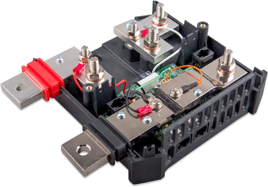
LED and most common problems
Green lit steadily
All OK — the module is measuring and communicating with the GX device.
Red lit steadily
Main fuse blown. Before inserting a new one, check for a short circuit and whether the circuit current exceeds the fuse rating.
Orange steady
Active alarm — state of charge, voltage, battery temperature or blown fuse. Details are shown on the GX screen.
Red flashing
Hardware fault in the module.
Alternating red and green
Calibration error.
Green flashing quickly or slowly
Bootloader initialisation or firmware update.
Orange flashing
Software error.
Cables are heating up
Check the tightness of the connections and the fuse (14 Nm, M10 version — 17 Nm), the cable cross-section and whether the lugs are crimped correctly.
Charging current negative or SoC always 100%
Negative wires swapped on the monitor — check where the battery side enters and where the system side enters.
State of charge is too high
The negative of one of the loads or chargers bypasses the system side, so its current is not measured.
No state of charge
The monitor is not synchronised, for example after installation or a power loss — it will synchronise after the battery is fully charged. If SoC rises too quickly or too slowly, check the set capacity: SoC does not match.
GX device does not see the module
Check the VE.Can port profile, terminators at both ends of the bus and the cables: GX does not see the device.
Most common questions about Lynx Shunt VE.Can
Which side should the batteries be connected to?
With the normal orientation, the batteries are on the left and the loads and chargers on the right (system side). The module can be mounted in any position — the set includes stickers with the label reversed.
Why is the state of charge overestimated?
Most often because one load or charger negative bypasses the module. All negatives must pass through the system side, otherwise their current is not included in the measurement.
Which port on the GX device?
The VE.Can port with the profile “VE.Can & Lynx Ion BMS (250 kbit/s)” — not the BMS-Can port. Terminators are fitted to the first and last device on the network, and the cables must be factory RJ45 UTP.
What main fuse?
You buy it separately and select it for the circuit’s maximum currents and voltages. The M8 version accepts CNN fuses, and the M10 version also accepts ANL and MEGA (on M6 studs) — Victron offers, for example, CNN 325 A / 80 V, and ratings from 35 to 800 A are available. If the positive busbar is already energised, the system receives voltage when the fuse is inserted.
What do you need to set after installation?
First of all, the battery capacity (200 Ah by default) and the “charged” voltage, 0.2–0.3 V below the charger’s float voltage. Tail current is 4% by default, charged detection time 3 minutes, Peukert 1.25. Lithium batteries require separate monitor settings.
Can I mix an M8 module with an M10 module?
No — M8 and M10 modules are not connected directly to each other. When planning the distribution setup, stick to one busbar size.
How do you power the GX device in such a system?
From the Lynx Shunt output or from a Lynx Distributor connected after it (RJ10 cable). On the VE.Can bus, remember the terminators on the first and last device and the factory RJ45 UTP cables.

Manufacturer documentation
Content checked against Victron Energy documentation (datasheets and manuals) — as of 19 September 2026. Report a content error · Revision log