
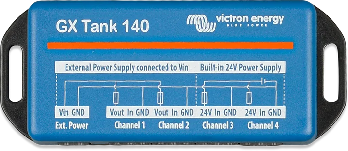
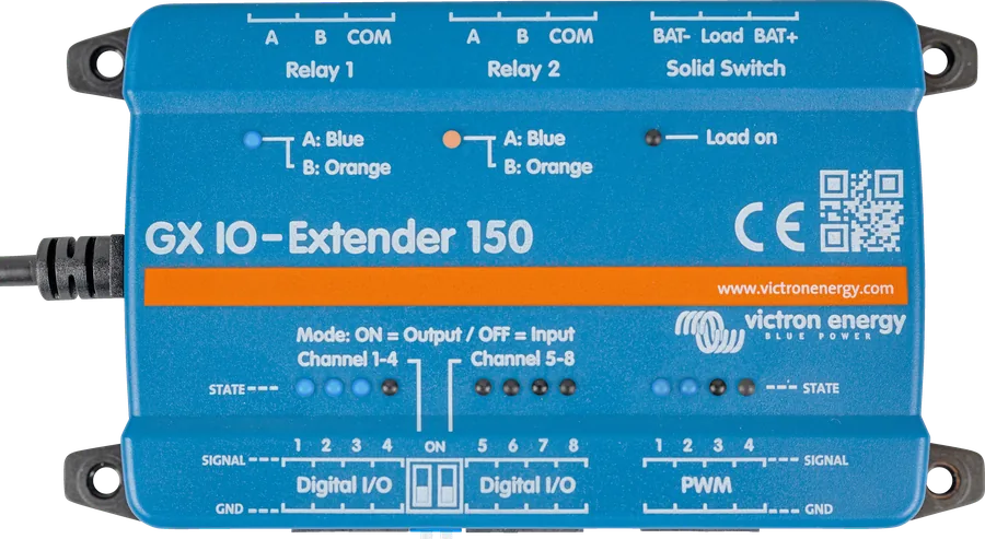
GX Tank 140 from above — wiring diagram printed on the enclosure: Ext. Power and channels 1–4
GX Tank 140
GX module (Cerbo GX, Ekrano GX) for connecting up to four liquid level sensors — 4–20 mA current or 0–10 V voltage sensors, including mixed types. It connects and is powered via USB. Fuel, fresh water or wastewater levels are shown on the GX screen, in Remote Console and in the VRM portal, and the GX can use them to switch a pump on.
- 4 channels
- 4–20 mA or 0–10 V
- 24 V for channels 3 and 4
- USB-powered
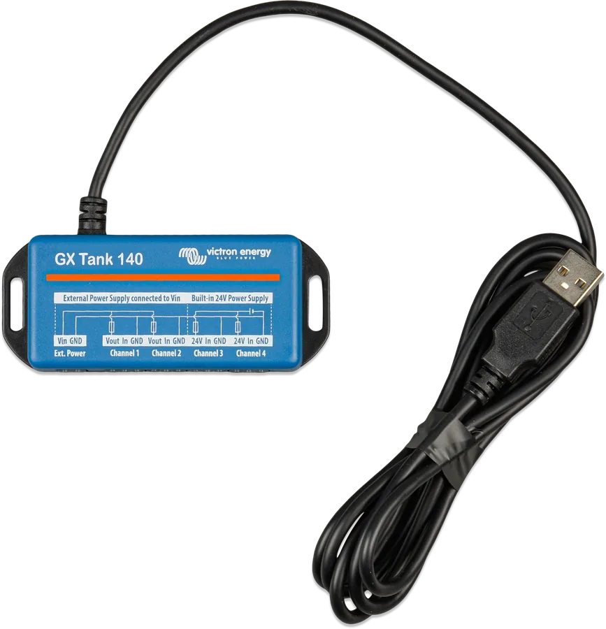
- 1.5 m USB cable
Tank levels on the GX screen and in VRM
On a boat, in a campervan or with a stationary generator, it is useful to know how much fuel, fresh water or wastewater remains — locally and remotely. GX Tank 140 reads industrial level sensors with current output (4–20 mA) or voltage output (0–10 V) and passes the result to the GX device.
Two channels power the sensors at 24 V from the module, so no additional supply wiring is needed. The other two distribute power from an external source connected to the module. On a boat, the GX device can also send tank levels to the NMEA 2000 network, for example to a navigation display.
- current and voltage sensors in any combination, set separately for each channel,
- configurable range — for example a 0–5 V sensor,
- alarm for out-of-range signal (faulty sensor or cable),
- USB cable isolated from the sensors — no ground loop with the GX.
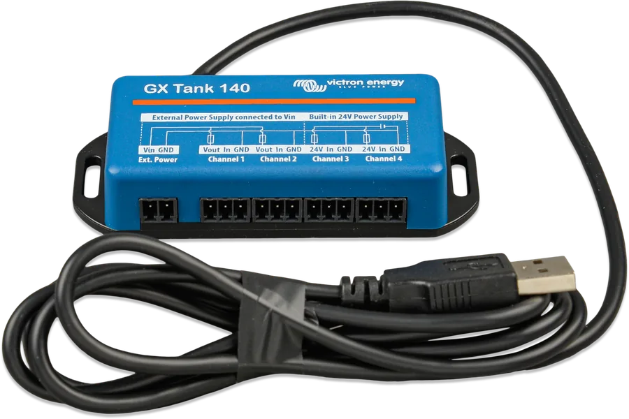
In September 2026 the GX Tank 140 product page is no longer available on victronenergy.com; the manual is still published. Before buying, check availability with your distributor. This sheet will also help people who already have this module installed.
What the GX Tank 140 can do
Four tanks
Each channel is a separate tank with its own name, liquid type (fuel, fresh water, grey water, live well, oil, wastewater) and unit.
Sensor power supply
Channels 3 and 4 — built-in 24 V (from USB, isolated) with a 20 mA fuse per channel. Channels 1 and 2 — supply from an external source via the Ext. Power terminal with a 20 mA fuse.
Tank shape
For irregular tanks, up to 10 points define the relationship between sensor reading and volume — for example, 50% signal = 25% volume. Linear interpolation is used between points.
Averaging
Averaging time 1–60 s (default 10 s) damps liquid sloshing, for example on a moving boat.
Pump control
The GX relay in “Tank pump” mode switches the pump on below the start level and off above the stop level — for example to top up a day tank.
GX, VRM and NMEA 2000
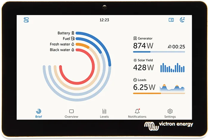
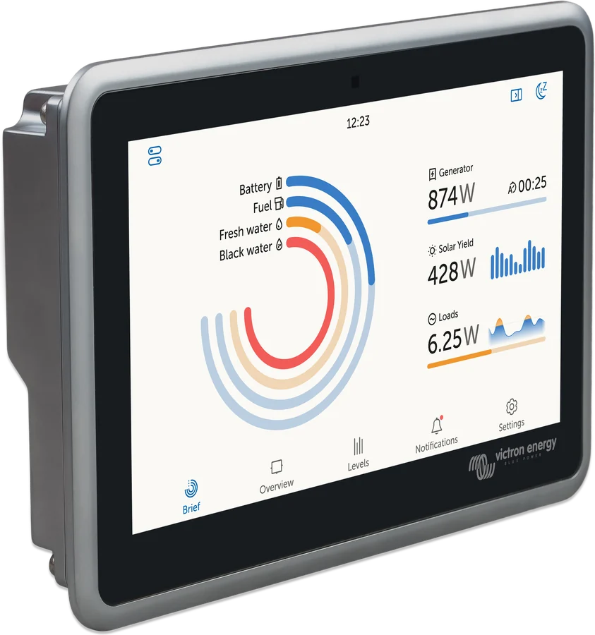
The “Boat and motorhome overview” and “Tank overview” pages on the GX, the device list, Remote Console, VRM (Dashboard and history) and — via the GX — the NMEA 2000 network.
How to connect GX Tank 140
Channels 1 and 2 with external supply, channels 3 and 4 with built-in 24 V. The GNDs of all channels are internally connected. Simplified diagram.
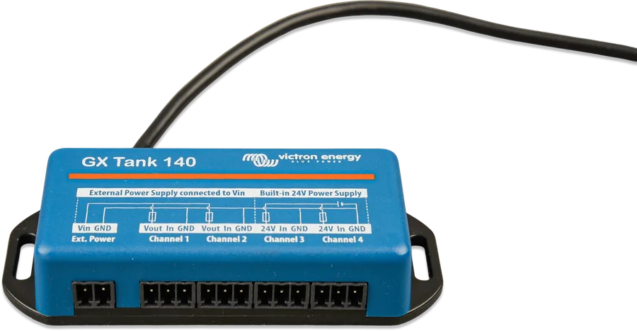
- USB to GXFixed 1.5 m cable; the module is powered via USB.
- Channels 1 and 2Sensors powered from an external source connected to Ext. Power (20 mA fuse).
- Channels 3 and 4Built-in 24 V, 20 mA fuse per channel.
- Voltage sensorVout/24V = supply (+), In = signal, GND = supply (−).
- Current sensorVout/24V and In; GND not connected.
Voltage and current sensor
| GX Tank 140 terminal | Voltage sensor (0–10 V) | Current sensor (4–20 mA) |
|---|---|---|
| Vout (ch. 1–2) / 24V (ch. 3–4) | supply (+), Vs+ — usually red | supply (+), Vs+ — usually red |
| In | signal 0–10 V or 0–5 V — colour varies | supply (−), Vs− — usually black or blue |
| GND | supply (−), Vs− — usually black or blue | not connected |
Always confirm wire colours in the sensor datasheet. In a current sensor, the module measures the voltage drop across the internal resistor between In and GND.
- Sensor compatibility: only 4–20 mA or 0–10 V sensors in normal operating range. Other types or input overvoltage can permanently damage the module.
- Ferrules: crimped ferrules are best, inserted straight into the spring terminals. Bare wire: strip at least 10 mm and insert with the orange button pressed in (precision screwdriver), with no stray strands.
- Sensor cable: shielded, twisted-pair, routed away from AC and DC cables; shield earthed to bare metal of the vehicle or boat.
- Grounds: the GND of all four channels is internally linked — they are not isolated from one another. USB is isolated from the sensors.
- Mounting: through the slots in the side flanges of the enclosure, using flat-head screws and washers, with a thread diameter of no more than 3.0 mm; do not overtighten.
Configuration in the GX device
- Sensor type: voltage (factory default) or current — set separately for each channel. A wrong choice will not damage the module.
- Sensor value when empty / full: the sensor operating range.
- Fluid type: fuel, drinking water, grey water, live well, oil, sewage — determines the icon and colour; if no name is set, the fluid type is shown.
- Volume unit: litre, cubic metre, UK gallon or US gallon.
- Custom shape: up to 10 points for irregular tanks.
- Averaging time: 1–60 s, 10 s factory default.
- Sensor value: raw reading without averaging — useful for troubleshooting.
- Device: tank name and VRM instance number.
- Disable unused channels in Settings → I/O → Analog Inputs, then use “Remove disconnected devices” at the bottom of the device list — no GX restart needed.
Automatic tank filling
- Relay functionSettings → Relay: set the GX relay function to “Tank pump”.
- Sensor and levelsSettings → Tank pump: select the sensor and set the Start level and Stop level.
- Auto modeThe pump starts when the volume drops below the Start level and stops when it rises above the Stop level. Modes: Auto, On, Off.
- OverviewThe levels and pump state are shown on the “Boat and motorhome overview” page (enabled in Settings → Display and language) — you can also change the pump mode there.
Most common problems
Sensor error
Appears when the signal goes out of range: voltage above 10 V or current below 4 mA or above 20 mA. Check that the sensor is compatible and working, and check the cables and connections.
Level stays at about 40–55%
With a current sensor, this is usually a triggered polymer fuse: about 11–13 mA flows through it continuously, which the module does not recognise as a fault. Look for a short circuit in the wiring.
Reading jumps around
Increase the averaging time (up to 60 s). Check that the sensor cable is shielded, twisted, and kept away from power cables.
Empty tanks in the list
All four channels are enabled by default. Disable the unused ones in Settings → I/O → Analog Inputs and remove them with “Remove disconnected devices”.
GX Tank 140 frequently asked questions
Does GX Tank 140 need separate power?
The module itself does not — it is powered from the GX device USB port. External power (Ext. Power terminal) is only needed for sensors on channels 1 and 2; channels 3 and 4 supply the sensors with 24 V from the module.
Does it support resistive sensors (e.g. 0–190 Ω)?
No. GX Tank 140 accepts only 4–20 mA and 0–10 V sensors (with the option of setting a narrower range, e.g. 0–5 V). Other sensor types are not compatible and may damage the module.
Can I mix current and voltage sensors?
Yes. The sensor type is set separately for each channel.
How do I read an irregularly shaped tank?
Use the Custom shape setting: up to 10 points describing what volume corresponds to a given sensor reading. GX interpolates linearly between points.
Will the levels appear on the boat navigation display?
Yes — the GX device can send tank levels to the NMEA 2000 network, where other displays, such as an MFD, can read them.
Can the USB cable be extended or disconnected?
The cable is 1.5 m long and permanently attached to the module. The manual does not describe extension.

Manufacturer documentation
Content checked against Victron Energy documentation (datasheets and manuals) — status as of 23 September 2026. Report an error in the content · Correction log