
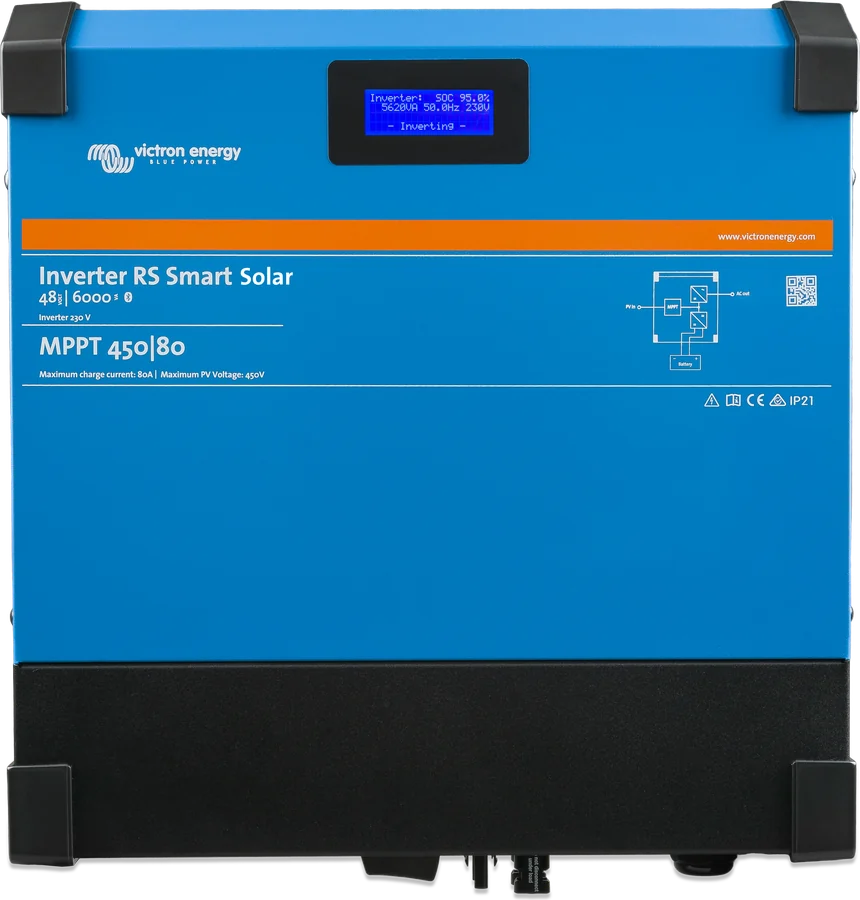
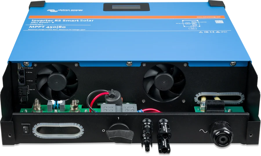
Inverter RS Smart Solar 48|6000 — front with display, manufacturer photo marked MPPT 450|80
Inverter RS Smart Solar 48/6000
A 48 V / 6 kVA inverter with a built-in 450 V MPPT solar charge controller and bidirectional DC-DC converter. The panels are connected directly to the inverter, and surplus PV power charges the battery. For off-grid installations — the unit has no AC input or mains charger.
- 48 V
- 230 V · 6 kVA
- MPPT 65–450 V
- 11 kg
- VE.Can · Bluetooth
Inverter and solar charge controller in one housing
Inverter RS Smart Solar combines three functions: a 230 V pure sine wave inverter, a bidirectional DC-DC converter and an MPPT solar charge controller. The converter charges the battery when there is excess from the panels, or draws energy from it when needed. The manufacturer intends it for off-grid installations that need 230 V.
You can also charge the battery from a PV inverter connected to the AC output (up to 5000 W). A generator requires a separate battery charger — the inverter itself has no AC input.
- full galvanic isolation between the panels and the battery,
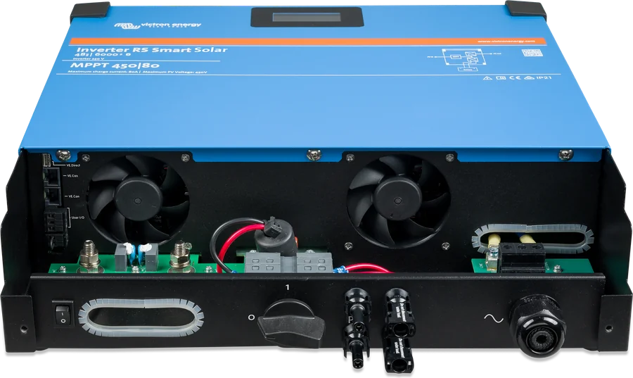
- built-in PV isolator on the underside of the enclosure,
- thanks to high-frequency technology it is light (11 kg); also quiet in operation.
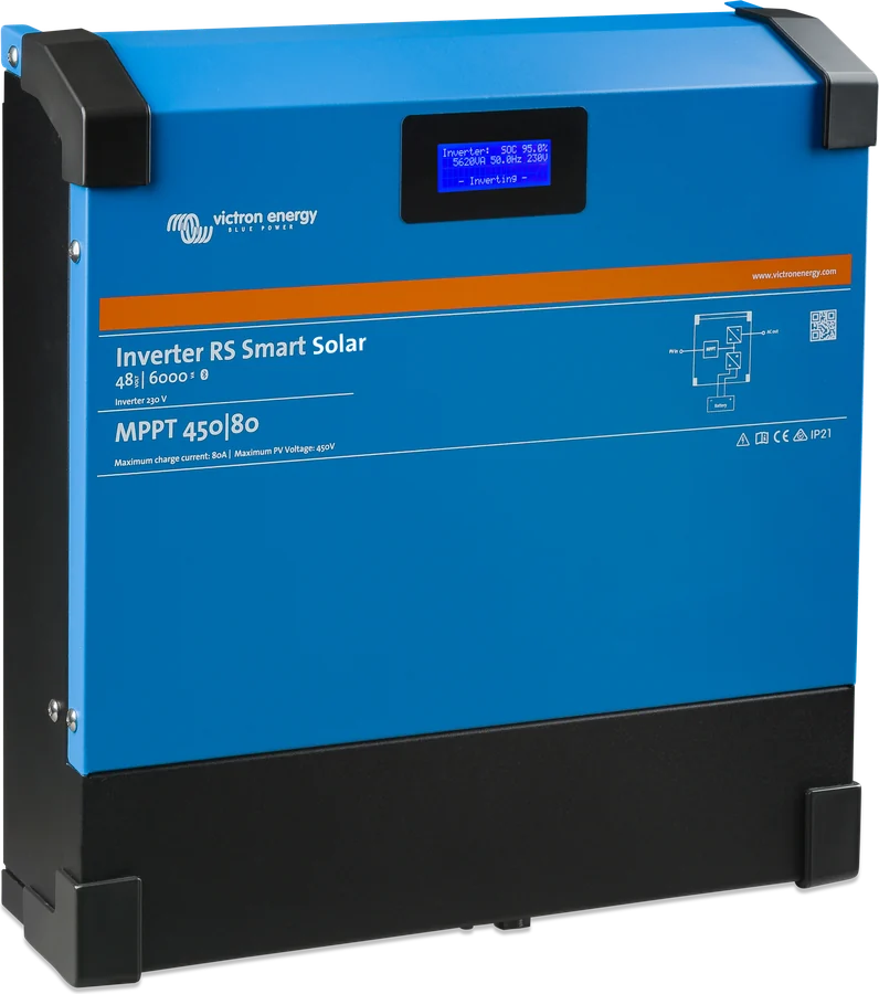

Two 3 kW trackers or one 4 kW?
The current datasheet and the data table in the manual state two PV inputs of 3 kW each (6 kW total, 12 A per tracker). The product page describes 4 kW MPPT, and the manual text mentions a 4000 W limit (80 A at a 50 V battery) and a model with one tracker — most likely this is the same version. The product code PIN482601000 is the same everywhere, and the manufacturer does not say how to distinguish them.
| Datasheet | Product page | |
|---|---|---|
| MPPT power | 2 × 3000 W | 4000 W |
| PV operating current | 12 A per tracker | 18 A |
| PV Isc | 16 A | 30 A (reverse polarity protection 20 A) |
| PV voltage | 65–450 V, 120 V start | 65–450 V per table (80–450 V in the description) |
The manual gives 12 A operating current for each tracker and protection up to 16 A; according to it, 30 A is the absolute maximum with correct polarity, outside the specification. The manufacturer’s photos show the enclosure marked “MPPT 450|80” and “Maximum charge current: 80A”, which matches the 4 kW version. Before selecting panels, check the nameplate and the data in VictronConnect (the STATUS screen shows the MPPT controller model). In the single-tracker version, several PV connectors are internally linked to one tracker — the strings should have the same number of the same type of panel.
What Inverter RS Smart Solar can do
6 kVA inverter
Continuous current 25 A AC. Peak 9 kW for 3 s and 7 kW for 4 minutes. With MPPT power, continuous power at 52 V and 25 °C rises by about 10%, to 5,800 W.
450 V MPPT
Starts at 120 V, operating range 65–450 V. Fast maximum power point tracking algorithm and built-in PV isolator.
Charging up to 100 A
From panels and from the inverter on the AC output, up to 100 A in total (above 60 V the current drops). Algorithm: bulk, absorption, float, optional equalisation.
AC-coupling
An inverter on the AC output (up to 5,000 W) charges the battery; Inverter RS limits it by raising the frequency. This allows the battery to charge to around 95%.
Up to 12 units
Up to 12 units in parallel via VE.Can, in three-phase up to 4 per phase — star only. You can mix solar and non-solar versions; in three-phase at least 3 units, firmware from v1.13.
PV insulation monitoring
Before start-up, insulation test of the panels to earth (threshold 100 kΩ) and 30 mA leakage protection. If there is an insulation fault, the inverter disconnects the AC output and the MPPT continues charging.
Display and Bluetooth
The display shows battery, inverter and controller parameters; configuration in VictronConnect. GX via VE.Can, GlobalLink 520 via VE.Direct.
Relay and inputs
Programmable relay (4 A up to 35 V DC, 1 A up to 70 V DC), two digital inputs, temperature sensor and voltage sense.
smallBMS / 2-wire BMS
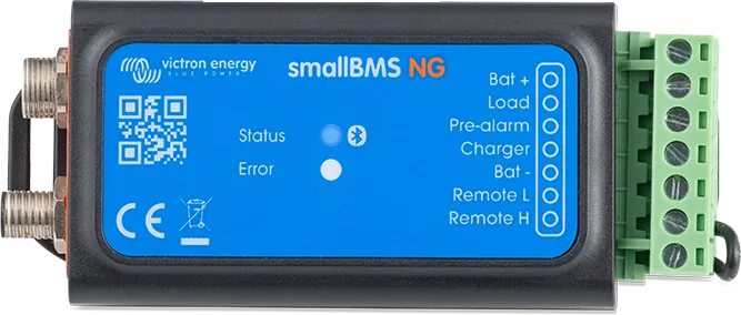
The remote input accepts signals from the BMS: “allow to discharge” switches off the inverter, “allow to charge” — charging from the panels.
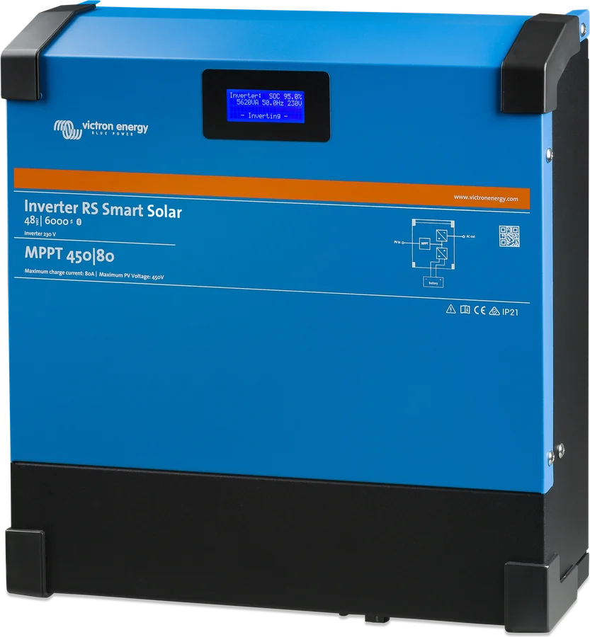
Main specifications
| Inverter | |
|---|---|
| Battery voltage | 38–62 V (start at 41 V, disconnect at 65.5 V) |
| Output | 230 V ±2%, 50 Hz ±0.1% (60 Hz possible) |
| Continuous power | 25 °C: 4,800 W at 46 V → 5,300 W at 52 V; 40 °C: 4,500 W; 65 °C: 3,000 W |
| Peak power | 9 kW for 3 s, 7 kW for 4 min |
| Continuous / short-circuit current | 25 A AC / 45 A |
| Efficiency | 96.5% at 1 kW, 94% at 5 kW |
| No-load consumption | 20 W |
| Low battery voltage | shutdown 37.2 V, restart 43.6 V (adjustable) |
| PV and charging (datasheet) | |
|---|---|
| PV voltage | max. 450 V, start 120 V, MPPT 65–450 V |
| PV current | 12 A operating, Isc 16 A |
| PV power | 6,000 W total, 3,000 W per tracker |
| PV insulation | pre-start test, 100 kΩ threshold; 30 mA leakage |
| AC-coupling | up to 5,000 W from the inverter on the AC output |
| Total charging | 100 A |
| Absorption / float | factory default 57.6 / 55.2 V, range 36–60 V |
- Enclosure
- steel, IP21, protection class I
- Dimensions / weight
- 425 × 440 × 125 mm, 11 kg
- Operating temperature
- −40 to +65 °C (datasheet)
- Battery / AC
- M8 bolts / 10 mm² terminals
- PV
- 2 × MC4 positive, 2 × MC4 negative
- Communication
- VE.Can, VE.Direct, Bluetooth
The documents differ in a few places: continuous power at 25 °C (datasheet 4,800–5,300 W, manual table 4,600–5,200 W), operating temperature (datasheet and manual table up to +65 °C, sections 3.1 and 6.8.2 of the manual and the product page — 60 °C, full solar power up to 40 °C) and minimum PV voltage for continued operation (65 V or 80 V). The manual table also lists “88 A from AC”, although the unit has no AC input.
Where Inverter RS Smart Solar sits in the system
Panels on the MPPT input, 48 V battery through a fuse, 230 V loads on the output. Hover over or tap a diagram element. Illustrative diagram.
- Panels → MPPTVoc < 450 V and < 8 × float; original MC4 only.
- 230 V outputLoads; never grid or generator.
- PV inverter (optional)AC-coupling up to 5,000 W, 1:1 rule.
- Battery → fuse35 mm² and 125 A up to 2 m, 70 mm² and 200 A up to 5 m.
- GX (VE.Can)Monitoring and VRM; strongly recommended if you have several units.
PV connection rules
The open-circuit voltage of the array must be lower than eight times the battery float voltage — at a float voltage of 54.0 V, that is 432 V. If this is exceeded, the unit reports “Over-charge Protection” and shuts down. Remedy: a higher float voltage or fewer panels in the string.
- No more than 450 V — overvoltage damages the charger and is not covered by the warranty. In winter Voc rises: the manufacturer recommends the MPPT calculator and a 10% margin.
- Reversed connection of an array with a short-circuit current above 16 A voids the warranty. Reverse PV polarity gives no message — charging current is zero and the unit heats up.
- Only original Stäubli MC4 connectors; panels of the same brand, type and model; no optimisers.
- Class A modules to IEC 61730 (non-isolated inverter on the AC side). The + and − conductors of the array insulated from earth, array frame earthed; in the system only one point connected to earth — at the battery.
Inverter RS Smart Solar, Inverter RS Smart or Multi RS Solar?
Inverter RS Smart Solar
An inverter with built-in MPPT — off-grid, where the battery is charged by panels. No AC input and no mains charger.
48 V · 6 kVA · MPPT 450 VInverter RS Smart
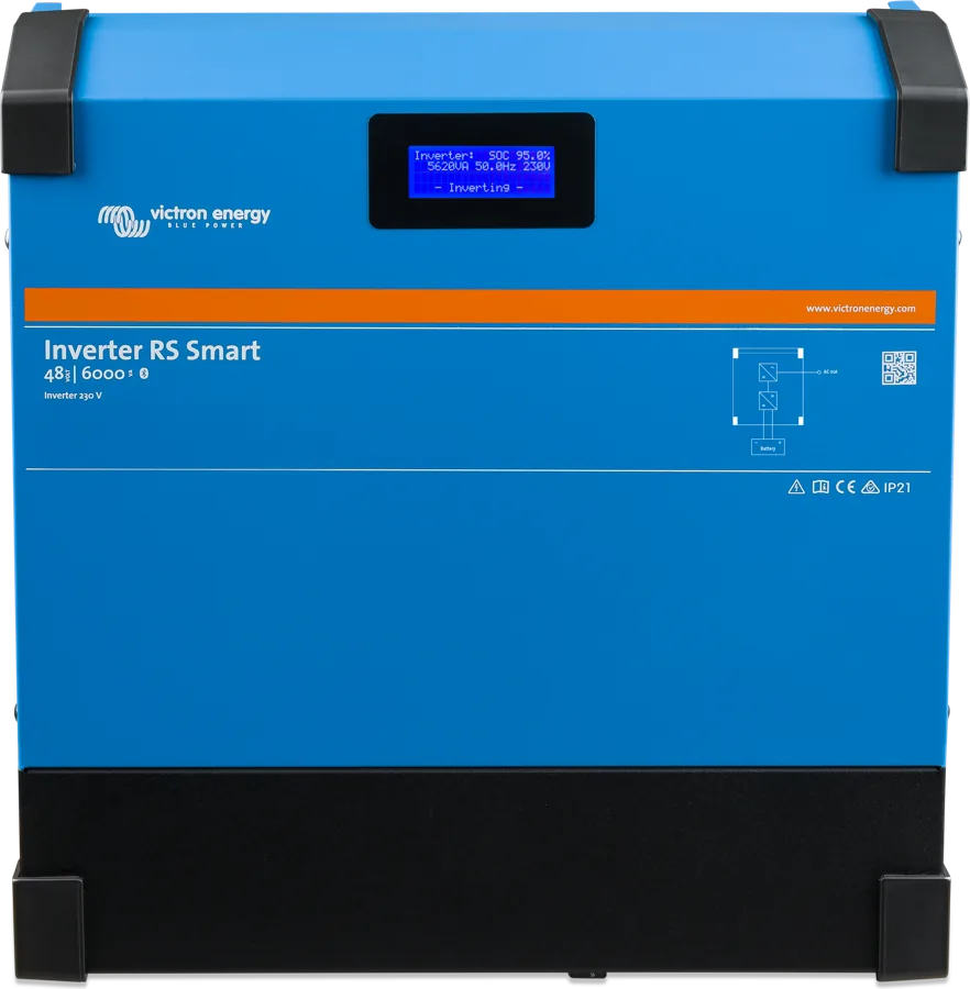
The same inverter without a controller — PV via a separate MPPT or a PV inverter on the AC output. Inverter RS datasheet.
48 V · 6 kVAMulti RS Solar
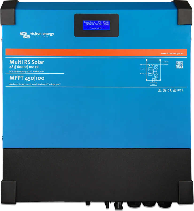
AC input comes from the mains or generator, and a charger. Multi RS Solar card · Multi RS19 Solar. Connecting Inverter RS and Multi RS in one system is currently unsupported.
+ AC input + chargerInstallation rules
There may be 400–500 V DC inside even after switch-off. Disconnect the battery, PV isolator and other sources, then wait at least 5 minutes. Do not remove the front cover. Installation only under the supervision of a qualified installer; cover the panels during installation.
The AC output terminals or the earthing point on the enclosure must have a permanent earth connection; in a vehicle the enclosure is connected to the chassis, on a boat — to the hull or grounding plate. The conductor from the enclosure terminal to earth must be at least the same cross-section as the PV conductors. If earth damage is suspected, switch the unit off and secure it against restart.
- Sequence: 1) check polarity and battery, 2) remote, relay and communication, 3) check polarity and PV array.
- Location: vertical, 30 cm above and below the unit, on a non-combustible surface, away from sun, moisture, soot, dust and salt, and away from flammable or corrosive gases and vapours. Never directly above lead-acid batteries.
- Battery terminals: lug, flat washer, spring washer, nut — max 14 Nm; do not loosen the lower nut soldered to the board. AC terminals: 1.2 Nm.
- Battery and PV cables: flexible Class 5 copper stranded wire (single strand max. 0.4 mm), insulation min. 90 °C; voltage drop on the battery cables above 2.5% is not acceptable.
| Cable length | Cross-section per pole | DC fuse | Minimum battery |
|---|---|---|---|
| 0–2 m | 35 mm² | 125 A | 200 Ah lead-acid or 50 Ah lithium |
| 2–5 m | 70 mm² | 200 A |
You must not connect the inverter output to the mains or a generator. AC terminals 10 mm², maximum output fuse 30 A, an RCD type A may be used — the built-in relay connects the output N to the enclosure so the RCD works. The manual does not specify the recommended AC cable cross-section or TN/TT earthing systems. More: earthing and RCD.
How to set it up
Set up in VictronConnect over Bluetooth (range about 20 m, one phone at a time) — on Windows via the VE.Direct–USB interface. If you lose the PIN, use the PUK code from the sticker to reset it to 000000.
- Battery: 48 V fixed voltage; presets Normal, High and LiFePO4 2-wire BMS; for LiFePO4, charging is blocked below 5 °C. Lithium is not equalised; turn off temperature compensation for lithium.
- BMS: Remote mode “2-wire BMS” — Remote H disables the inverter (allow to discharge), Remote L disables charging from PV (allow to charge). In this mode the unit will not start without a BMS; the manufacturer recommends smallBMS with Victron batteries.
- DVCC and BMS-Can override the charger settings — you can see this in VictronConnect and GX; this is not a fault.
- Dynamic cut-off (disabled by default) — do not enable it when other loads are connected to the same battery.
Parallel and three-phase operation (VE.Can, terminators at both ends): up to 12 units, in three-phase the same number on each phase, at most 4 per phase, star only; one common battery bank; each unit separately protected on AC and DC. Set the settings in each unit. Configure system mode before connecting loads — the AC output then disappears for a few seconds. Do not enable “Continue with missing phase” with three-phase loads. The manufacturer notes that these systems are not for inexperienced installers; in one place the manual also contradictorily states “one unit per phase”.
What the Inverter RS Smart Solar does not do
The manual does not have a separate section on limitations (although it refers to one in the data table) — below are the limitations collected from the full text.
No AC input
There is no mains charger or source transfer switch. Generator — via a separate battery charger.
AC coupling up to approx. 95%
With a PV inverter on the output, the battery will not charge to 100% — full charging requires PV modules on the MPPT.
Charging up to 100 A
Total current from PV and AC coupling; above 60 V battery voltage drops linearly to 5 A at 62 V.
No VE.Smart
It does not work with the VE.Smart network (for example, Smart Battery Sense). GX only via VE.Can.
No split-phase and delta
Single-phase or three-phase in star. Connection with Multi RS is currently not supported — according to error 70 description, newer Inverter RS units may support it; check with your supplier.
No battery reverse-polarity protection
Reverse battery connection is not protected and is not covered by the warranty.
Most common faults
Typical situations from the manual. You can check the error number from the display or VictronConnect in the RS device error codes section — the manual includes a general list of MPPT codes.
No response, blank display
Check the main switch (bottom, left) and PV isolator (bottom, centre), voltages, cables and fuses. If needed, charge the battery from another source.
MPPT not charging
Start requires 120 V at the PV input. In VictronConnect, “Why is the charger off?” will show the cause: too little PV, shut-down from the BMS, low lithium battery temperature.
The inverter has shut down AC output, MPPT is charging
PV module insulation resistance too low. Do not touch metal parts, call a technician; check PV cables and connectors.
PV safety relays have operated
The relay flag shows “!”, the green LED on the board is off, the PV array is short-circuited. Do not try to reset it — return the unit to the supplier.
Shuts down under overload
After three restarts within 30 s it remains off — disconnect the load, switch the unit off and on.
Shuts down on low battery
After three cycles it stops trying, but the MPPT keeps charging; after 4 shutdowns it will switch on itself when the voltage stays above “Charge detect” for 30 s.
Battery not fully charged
Too little PV (check the 30-day history — does it reach float), load too high, voltage drop on the cables above 2.5%, or incorrect temperature compensation.
Burnt MC4 connectors
Rigid or soldered conductors, cable too thin, over 30 A per pair of connectors, or poorly crimped MC4s — usually not covered by warranty.
Full power not achievable
PV array too small or temperature above 40 °C — full solar power up to 40 °C. In a cabinet, provide air inlets and outlets.
Most common questions about the Inverter RS Smart Solar
Can I charge the battery from the mains or a generator?
Not directly — the Inverter RS Smart Solar has no AC input. The manufacturer specifies a separate battery charger with a generator. For charging from the mains or a generator, use Multi RS Solar.
How many panels can I connect?
According to the datasheet, two inputs of 3 kW each (6 kW total), 12 A working current per tracker. String Voc below 450 V and below 8 × battery float voltage. First check which version you have — see two MPPT versions.
Which fuse and cable for the battery?
Up to 2 m: 35 mm² and 125 A fuse; from 2 to 5 m: 70 mm² and 200 A. Minimum battery: 200 Ah lead-acid or 50 Ah lithium.
How many inverters can I connect?
Up to 12 in parallel via VE.Can; in a three-phase system the same number on each phase, at most 4 per phase. You can connect solar and non-solar versions; connection with Multi RS is currently not supported.
Can I add a PV inverter on the output?
Yes, up to 5000 W, while keeping the 1:1 rule and the minimum battery size from the AC Coupling manual. The Inverter RS limits the PV inverter by raising frequency (stop at 53.2 Hz); the setup was tested with Fronius (MG50/60). The battery will then charge to about 95%.
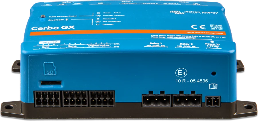
How do I connect to Cerbo GX?
Only via VE.Can (with terminators). The VE.Direct port supports GlobalLink 520 or a computer via VE.Direct–USB.
The unit does not switch on — what should I check?
Main switch on the bottom left, Remote L–H bridge on the I/O terminal strip, Remote mode (in “2-wire BMS” it will not start without a BMS) and battery voltage — start from 41 V.
How is it different from the Inverter RS Smart?
It has a built-in MPPT charge controller, PV isolator and module insulation monitoring. The inverter section has mostly the same parameters — differences include output short-circuit current (45 A in the Solar datasheet), additional solar power up to 5800 W and AC-coupled charging up to about 95%. Inverter RS Smart datasheet.
Devices it works with most often
Content checked against Victron Energy documentation (datasheets and manuals) — as of 22 September 2026. Report a content error · Revision log