
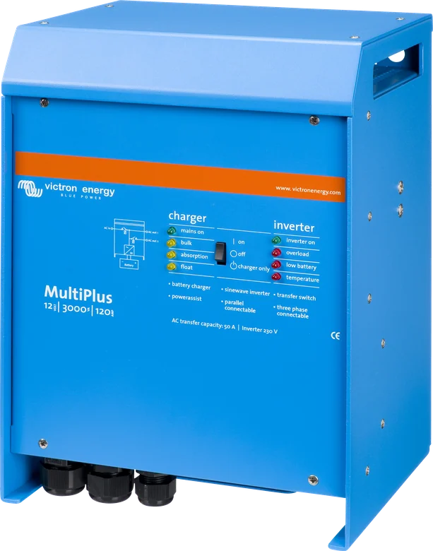
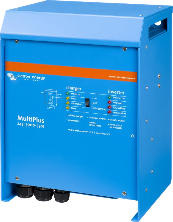
MultiPlus 12|3000|120-50 — front with charger and inverter LED panel
MultiPlus 800 VA–20 kW
Inverter/charger and transfer switch in one. For 12 V, 24 V or 48 V systems. PowerControl limits current from the grid, shore power or generator. PowerAssist supplements the missing power from the battery. The main AC output takes over in less than 20 ms.
- PowerControl / PowerAssist
- VE.Bus
- 800 VA–20 kW
- 12 / 24 / 48 V
Inverter, charger and switch in one
The MultiPlus does three things at once. When external power is available — from the grid, campsite hook-up or generator — it passes it through to the loads and charges the battery. When the supply disappears, in less than 20 ms it takes over and produces 230 V from the battery.
Two functions manage the AC source: PowerControl limits the current drawn to what the shore power connection or generator can handle, while PowerAssist adds the missing power from the battery instead of blowing a fuse.
- computers and fridge keep running when the grid fails,
- kettle on a campsite with a 6 A fuse — the battery adds the missing power,
- up to six units in parallel (models up to 5 kVA) or three in a three-phase system.
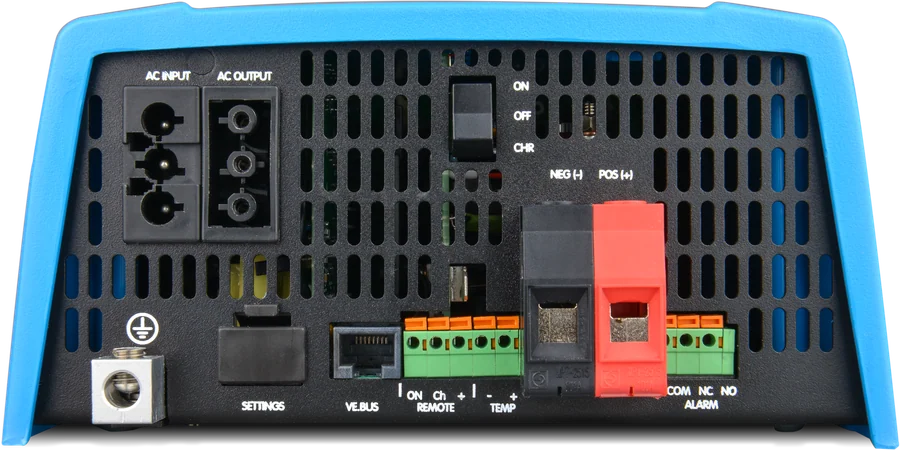

What the MultiPlus does
UPS on the AC output
When the grid fails, the MultiPlus takes over the loads in less than 20 ms — computers keep running without interruption.
PowerControl
Limits the current drawn from the generator or shore power. The unit takes other AC loads into account and uses only the surplus for charging.
PowerAssist
It supplements missing AC source power from the battery, and any surplus goes back into charging. The 3000 VA manual gives a range of 2.3–16 A (16 A models) and 5.3–50 A (50 A models).
4-stage charger
Adaptive: bulk – absorption – float – storage, with BatterySafe. Storage activates after 24 h without discharge and reduces float to 2.2 V per cell (13.2 V at 12 V).
Second AC output
On 3 kVA and larger models. It is live only when AC is present at the input — for example, a water heater. On the 3000 VA model it is up to 16 A, with about a 2 min delay for generator stabilisation; on the 5000 VA model the datasheet gives 50 A.
Starter battery output
Second DC output with a current of 4 A and a slightly lower voltage — only in 12 V and 24 V models. 48 V models do not have it.
Parallel and three-phase
Up to six identical units in parallel (models up to 5 kVA); three identical units provide three-phase output. Delta (Δ) configuration is not supported. 20k: parallel operation with an external AC switch.
VE.Bus and monitoring
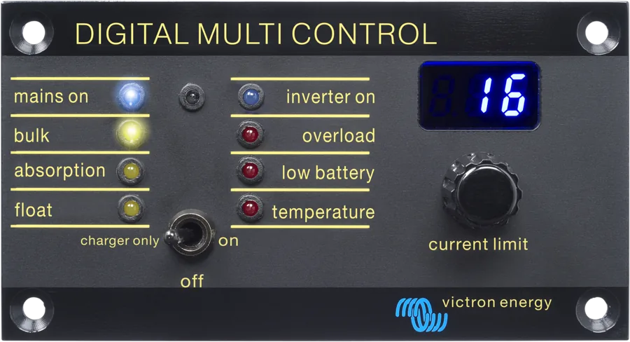
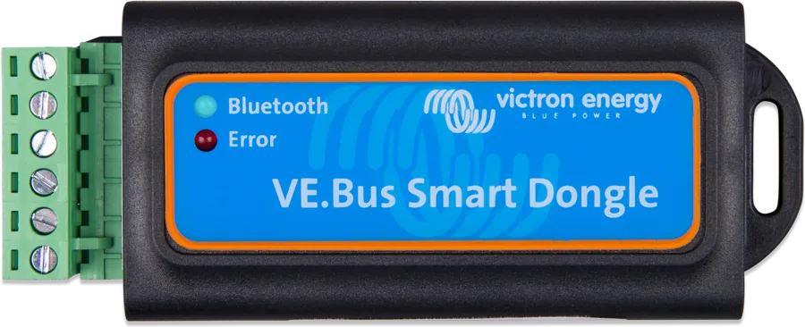
Digital Multi Control panel, GX device and VRM portal, or the VE.Bus Smart dongle with Bluetooth. Configuration: VEConfigure3 and MK3-USB.

800 VA–20 kW range
The main datasheet covers models from 800 VA to 5 kVA; the largest MultiPlus 48/20k/250-100 has a separate datasheet and manual — description below. The manual from which the DC cable cross-sections, fuses, tightening torques and settings are taken applies to the 3000 VA 230 V models with firmware xxxx400 or later.
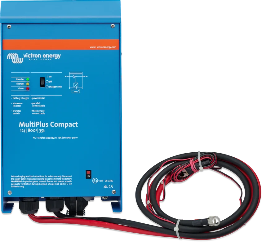
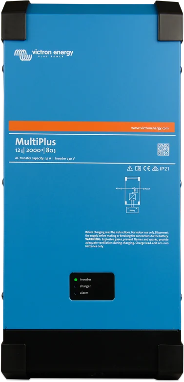
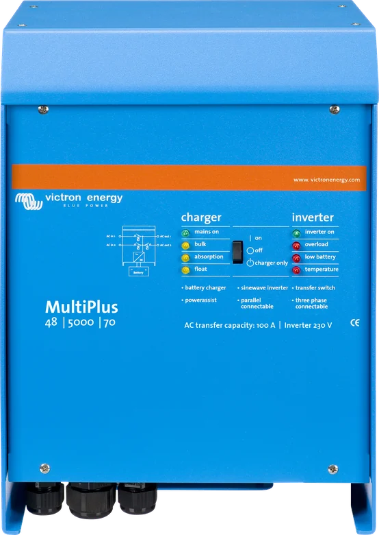
| Model | Battery | Power at 25 °C | Power at 40 °C | Power at 65 °C | Peak | Charging | Transfer | Weight |
|---|---|---|---|---|---|---|---|---|
| C 12/800/35 | 12 V | 800 VA / 700 W | 650 W | 400 W | 1600 W | 35 A | 16 A | 10 kg |
| C 24/800/16 | 24 V | 800 VA / 700 W | 650 W | 400 W | 1600 W | 16 A | 16 A | 10 kg |
| C 12/1200/50 | 12 V | 1200 VA / 1000 W | 900 W | 600 W | 2400 W | 50 A | 16 A | 10 kg |
| C 24/1200/25 | 24 V | 1200 VA / 1000 W | 900 W | 600 W | 2400 W | 25 A | 16 A | 10 kg |
| C 12/1600/70 | 12 V | 1600 VA / 1300 W | 1200 W | 800 W | 3000 W | 70 A | 16 A | 10 kg |
| C 24/1600/40 | 24 V | 1600 VA / 1300 W | 1200 W | 800 W | 3000 W | 40 A | 16 A | 10 kg |
| C 12/2000/80 | 12 V | 2000 VA / 1600 W | 1400 W | 1000 W | 4000 W | 80 A | 30 A | 12 kg |
| C 24/2000/50 | 24 V | 2000 VA / 1600 W | 1400 W | 1000 W | 4000 W | 50 A | 30 A | 12 kg |
| 12/3000/120 | 12 V | 3000 VA / 2400 W | 2200 W | 1700 W | 6000 W | 120 A | 16 A or 50 A | 18 kg / 19 kg |
| 24/3000/70 | 24 V | 3000 VA / 2400 W | 2200 W | 1700 W | 6000 W | 70 A | 16 A or 50 A | 18 kg / 19 kg |
| 48/3000/35 | 48 V | 3000 VA / 2400 W | 2200 W | 1700 W | 6000 W | 35 A | 16 A or 50 A | 18 kg / 19 kg |
| 24/5000/120 | 24 V | 5000 VA / 4000 W | 3700 W | 3000 W | 10 000 W | 120 A | 100 A | 30 kg |
| 48/5000/70 | 48 V | 5000 VA / 4000 W | 3700 W | 3000 W | 10 000 W | 70 A | 100 A | 30 kg |
| Industrial model (separate datasheet) | ||||||||
| 48/20k/250-100 | 48 V | 20 000 W | 18 000 W | 14 000 W | 25,000 W (1 min) | 250 A | 100 A | 80 kg |
Continuous VA power is given for a non-linear load with a crest factor of 3:1, and the house battery charging current is up to 25 °C. Mass of the 3000 VA models: datasheet 18 kg, manual 19 kg; dimensions (manual) 364 × 295 × 221 mm. Do not lift the 5000 VA models, which weigh 30 kg, without help.
- Inverter output
- 230 VAC ±2%, 50 Hz ±0.1% (60 Hz possible)
- AC input with grid power
- 187–250 V, cos φ > 0.8 (up to 5 kVA)
- Charger AC input
- 187–265 VAC, power factor 1
- DC range
- 9.5–17 V · 19–33 V · 38–66 V (20k: 38–60 V)
- Absorption / float / storage
- 14.4 / 13.8 / 13.2 V (×2 i ×4)
- Starter battery
- 4 A, 12 V and 24 V only
- Maximum efficiency
- 92–95% depending on model (20k: 96%)
- No-load consumption
- 8–35 W, 20k: 65 W (AES and Search reduce this)
3000 VA models: maximum continuous output current 11 A~, output short-circuit current 32 A peak for 1 s, power factor ±0.8, DC input current 250 / 125 / 65 A (12 / 24 / 48 V). 5000 VA models: 19 A~, 53 A peak for 1 s, DC input current 238 A (24 V) and 118 A (48 V). 120 V models are available to order — the datasheet does not specify their parameters.
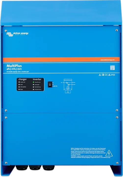
MultiPlus 48/20k/250-100 — 20 kW in a single enclosure
The largest classic MultiPlus: 20 kW continuous power at 25 °C (18 kW at 40 °C, 14 kW at 65 °C), 21 kW for 5 hours after a cold start and 25 kW peak for one minute. Charges a 48 V battery at up to 250 A (240 A at 40 °C).
It has one AC input with a 100 A transfer switch. PowerAssist adds up to 20 kW, that is about 87 A, so with a 100 A input you can draw up to 187 A from AC-out-1.
- Three phases: three units form a three-phase system. For parallel operation, the manufacturer recommends an external AC switch (manual “MultiPlus-II External Transfer Switch”).
- ESS and grid: when operating in parallel with the grid, an external 100 A current transformer is required (optional). PowerAssist range 11–100 A in both systems.
- 30 kW limit: the unit has fixed protection thresholds and the manual forbids connecting it in a system above 30 kW at one grid connection point — three 20k units (60 kW) at one point exceed this limit.
- AC-out-2 up to 50 A — only when powered from outside, returns after about 2 minutes.
- Efficiency up to 96%, no-load consumption 65 W (AES 40 W, Search 13 W). Aluminium IP20 enclosure, 616 × 422 × 357 mm, 80 kg.


| 48/20k/250-100 | According to the manual |
|---|---|
| Battery | 450–1400 Ah, 800 A DC fuse |
| DC cables | 2 × 120 mm² per pole (0–5 m), 2 × 185 mm² (5–10 m); copper with 90 °C insulation, not in enclosed conduit |
| Battery terminals | four M8 bolts (2 positive, 2 negative), 12 Nm, wrench with insulated socket |
| AC input | fuse or circuit breaker rated at up to 100 A; with a weaker source, proportionally less |
| AC-out-1 | in series, RCD (type A is sufficient) and protection matched to the load — up to 187 A with PowerAssist |
| AC-out-2 | up to 50 A (datasheet), terminals up to 2 Nm |
| Disconnectors | every installation must have a means of disconnecting the AC and DC circuits; with fuses — separate disconnectors |
The datasheet and the 20k manual differ on the battery temperature sensor: the datasheet says “Yes”, while the manual says it is not supplied for 48 V models. The starter battery output (4 A) is only on 12 and 24 V models, so the 20k does not have it.
Where the MultiPlus sits in the system
Schematic overview of a campervan or boat system. Hover over a diagram element or touch it to see the description.
- Mains / generator → AC-inExternal power. PowerControl and PowerAssist keep the current within limits.
- MultiPlusTransfers mains power to the loads and charges the battery, or produces 230 V from the battery.
- AC-out-1 → 230 V loadsThey work all the time — from grid or from battery. Switchover is under 20 ms.
- AC-out-2 → water heaterOnly when powered from outside (3 kVA models and above), so as not to discharge the battery.
- Battery → DC fuseFuse between the battery and the MultiPlus. Choose cable cross-section and rating to suit the model.
- Starter batterySeparate 4 A output, 12 V and 24 V models only.
- Digital Multi Control (VE.Bus)Switching on and input current limit. Instead of the panel, you can use a GX device and VRM.
Where everything connects
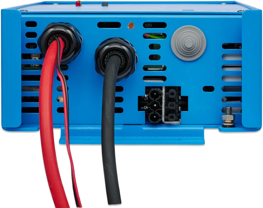
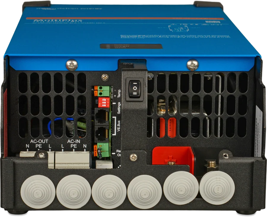
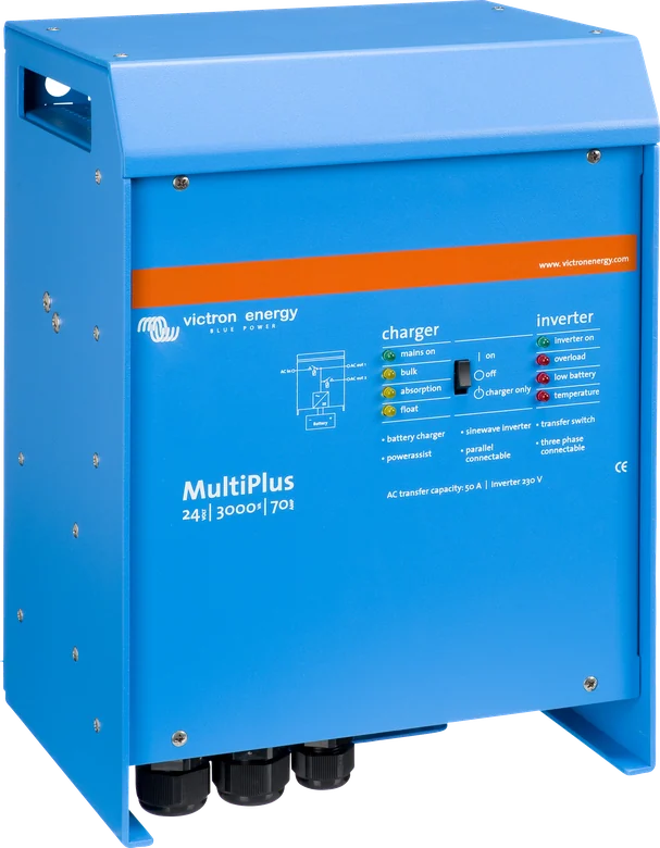
- Battery — terminal torque up to 12 Nm, with a torque wrench and insulated socket. Fuse and cable cross-section according to the model: table below.
- AC input and output — screw terminals, maximum 1.6 Nm. 3 kVA models and above have a second AC-out-2, active only when there is input power.
- Starter battery — separate 4 A DC output at slightly lower voltage, only on 12 V and 24 V models.
- Temperature sensor — included (except 48/20k, where the manual says it is not supplied); according to the manual, the 3000 VA one is insulated and fitted on the battery negative terminal.
- Voltage sense — two 0.75 mm² wires measure voltage directly at the battery; compensation for voltage drop up to 1 V per pole.
- VE.Bus — two RJ45 sockets for the Digital Multi Control panel, GX device, VE.Bus Smart dongle or parallel connection. Models 3000 VA and 5000 VA have a general-purpose port for BMS communication.
MultiPlus, MultiPlus-II or Quattro-II?
MultiPlus
One AC input, PowerControl and PowerAssist, parallel and three-phase operation. It is ideal in a campervan, on a boat and in a cabin where simple, reliable 230 V power matters.
800 VA – 20 kW · 12 / 24 / 48 VMultiPlus-II
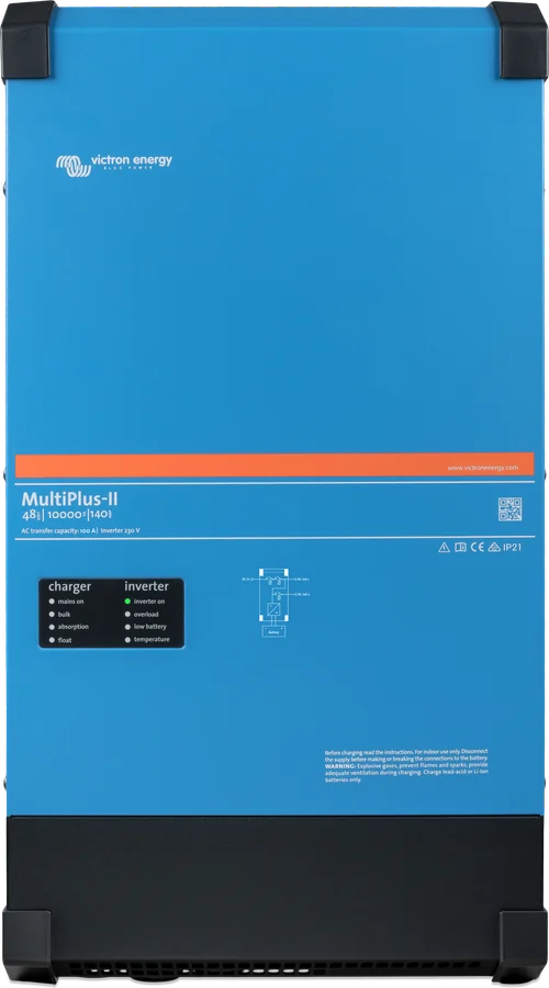
A newer design for ESS installations working with the grid and solar. MultiPlus-II datasheet, version with integrated GX: MultiPlus-II GX.
ESS · two AC outputsQuattro-II
Two AC inputs — grid and generator — with automatic source selection. Choose it if you have shore power and a generator and do not want to swap plugs. Quattro-II datasheet.
AC-in-1 + AC-in-2Two AC inputs for higher power or, at 12 V, the classic Quattro 3–15 kVA. One input and 20 kW in a single enclosure — MultiPlus 48/20k.
Where and how to hang the MultiPlus
This is a protective class I device: the AC input and output must have continuous earthing. Only a qualified electrician may change settings, and when setting the charger you must disconnect the AC input. Before maintenance, switch off the AC supply and disconnect the battery. There are no user-serviceable parts inside — do not remove the front panel.
- At least 10 cm of clear space around the unit (cooling). Vertical mounting preferred; horizontal is permitted.
- Never directly above batteries. Do not install where there is a risk of gas or dust explosion, or in wet or dusty environments.
- Fire-resistant surroundings: no chemicals, plastics, curtains or fabrics nearby. Ventilation openings must remain clear.
- Torque on battery connections: maximum 12 Nm, with a torque wrench and insulated socket. AC terminals: maximum 1.6 Nm.
- Operating temperature −40 to +65 °C (fan cooled), non-condensing humidity up to 95%, altitude up to 2000 m, IP20 aluminium enclosure.
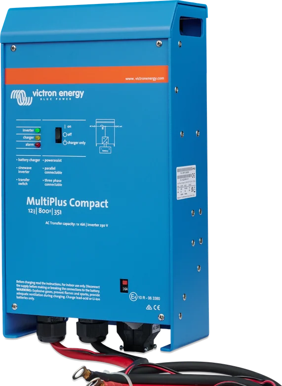
The earth relay automatically connects the output neutral to the enclosure when no external AC is present. On a boat, do not connect the installation directly to shore earth — this risks galvanic corrosion; use an isolation transformer. More: earthing and RCD.
The battery temperature sensor is included in the box (except with the 48/20k — there, according to the manual, it is not supplied); according to the manual the 3000 VA is isolated and is fitted on the battery negative. Voltage sense leads: 0.75 mm², voltage drop compensation up to a maximum of 1 V per terminal.
The factory charging voltages may not suit your batteries — check the battery manufacturer’s documentation before the first charge.
Models up to 5 kVA: up to six identical units (20k — with an external AC switch); DC cables of the same length and cross-section, at least 10 cm ventilation. Run the UTP cables directly between the devices and the panel, with no splitters. At DC distribution points, the cross-section from the battery to the distribution must be at least equal to the sum of the cross-sections to the individual MultiPluses. There may be only one panel or remote switch in the system.
How to connect the MultiPlus 3000 VA
The values below come from the manual for the 3000 VA 230 V models. The datasheet does not give DC cable cross-sections or DC fuses for the 800–2000 VA and 5000 VA models — for those, choose them according to the general rules: DC cable cross-sections and fuses.
| Model | DC fuse | 0–5 m | 5–10 m | Battery capacity | DC current |
|---|---|---|---|---|---|
| 12/3000/120 | 400 A | 2 × 50 mm² per terminal | 2 × 70 mm² per terminal | 400–1200 Ah | 250 A |
| 24/3000/70 | 300 A | 50 mm² per terminal | 2 × 50 mm² per terminal | 200–700 Ah | 125 A |
| 48/3000/35 | 125 A | 35 mm² per terminal | 2 × 35 mm² per terminal | 100–400 Ah | 65 A |
| AC circuit | Protection according to the 3000 VA manual |
|---|---|
| AC-in (transfer 16 A) | fuse or circuit breaker, maximum 16 A, cable cross-section selected to suit the protection; if the AC source has a lower permissible value, reduce the protection |
| AC-in (transfer 50 A) | maximum 50 A, cable cross-section selected to suit the protection; with a weaker source — correspondingly less |
| AC-out-1 (16 A) | in series, an A-type RCD and a fuse or circuit breaker selected to suit the load; maximum 32 A (PowerAssist up to about 13 A plus 16 A input) |
| AC-out-1 (50 A) | in series, an A-type RCD and a fuse or circuit breaker selected to suit the load, maximum 63 A |
| AC-out-2 | up to 16 A; in series, an RCD and a fuse, maximum 16 A |
What the MultiPlus comes with from the factory
The factory settings (3000 VA manual) are set up for Victron gel batteries and single-unit operation. With a different battery, check the charging voltages in its documentation before you charge it for the first time.
| Inverter output | 230 V / 50 Hz (adjustable 210–245 V) |
| AC input range | 180–265 V, 45–65 Hz |
| Battery type | Victron Gel Deep Discharge (AGM Deep Discharge also fits) |
| Charge curve | four-stage adaptive with BatterySafe |
| Charge current | 75% maximum |
| Enabled | UPS, PowerAssist, earth relay, charger, bulk protection (10 h) |
| Disabled | AES, automatic equalisation, dynamic current limiter, WeakAC |
| Programmable relay | alarm function; AC 230 V / 4 A, DC 4 A up to 35 V and 1 A up to 60 V. Models with 16 A transfer have one relay, with 50 A transfer — three |
Switch on the unit. The “on” position is full operation: when the AC voltage is within specification, mains is passed to the output and the charger charges. The “charger only” position leaves just the charger — if mains fails, the inverter does not start, so the battery does not supply the AC loads.
Energy saving. Search mode reduces idle consumption by about 70% (with a resistive load it switches off at 40 W and switches on at 100 W). AES reduces consumption with no load or a small load by about 20% — only in standalone operation. WeakAC reduces the maximum charge current by about 20%.
Equalisation lasts one hour at a voltage 1 V higher than absorption for 12 V (2 V for 24 V) and with current limited to one quarter of the setting. Disconnect DC loads before it starts — the voltage may be too high for them. The bulk phase is limited by bulk protection to 10 hours; you can disable it only in VEConfigure.
Solar PV and lithium batteries. The MultiPlus operates off-grid and with mains; software for detecting mains failure is available. After reaching absorption, the Multi or Quattro can switch off the PV inverter by shifting the output frequency by 1 Hz. The manual states compatibility with lithium-ion batteries, but only the 3000 VA, 5000 VA and 20k models have a general-purpose port for communication with a BMS.
| DIP switch setting (standalone operation, 3000 VA) | Values |
|---|---|
| ds8–ds6 — AC current limit | 6 A (1.4 kVA at 230 V), 10 A, 12 A, 16 A; in models with 50 A transfer, also 20 A, 25 A, 30 A and 50 A. The off / off / off combination is 6 A |
| ds4–ds3 — charge current | 25%, 50%, 75% or 100% (factory 75%) |
| Saving settings | after the first step, hold the Up button for 2 s, after the second — Down for 2 s |
Firmware. The manual applies to version xxxx400 or later. Older units can be updated when the 7-digit number starts with 26 or 27; with 19 or 20 — no. If the update fails: firmware update. Export to the grid requires enabling compliance with the national grid code in VEConfigure; later disabling requires a password, and if the local grid code is not supported — an external certified interface.
What lights and what flashes
On the inverter: inverter on, overload, low battery, temperature. On the charger: mains on, bulk, absorption, float. Current flash codes: the Victron Toolkit app. The meaning of the combinations also in the LED decoder. VE.Bus codes: VE.Bus error codes.
- inverter on lit — inverter on, supplying the load.
- overload flashing — rated power exceeded. Lit — shut down due to overload or short circuit.
- low battery flashing — battery nearly empty. Lit — shut down due to battery voltage too low.
- temperature flashing — internal temperature is approaching the critical level. Lit — shut down due to electronics temperature too high.
- Alternating flashing — battery nearly empty and rated power exceeded.
- overload and low battery flashing together — battery terminal ripple voltage too high; the inverter may shut down.
- bulk lit, mains on the output — bulk phase. If the absorption voltage has not yet been reached: BatterySafe mode.
- PowerControl: AC output current equal to the set maximum input, charge current reduced to 0.
- PowerAssist: the load demands more than the input limit, the inverter supplies the missing current from the battery.
- bulk and absorption flashing synchronously — voltage sense error (deviation over 7 V); the unit remains in normal operation.
- absorption and float flashing synchronously — extremely unlikely temperature (faulty or wrongly connected sensor).
- mains on flashes, no output voltage — “charger only”: the unit rejects the mains or is still synchronising.
Protections (datasheet): output short circuit, overload, battery voltage too high or too low, temperature too high, 230 VAC on the inverter output, input ripple too high.
Symptom and what to do about it
The MultiPlus shows its status with eight LEDs — four for the charger and four for the inverter. Below are the symptoms from the manual and datasheet; flashing combinations are described in the LED decoder.
No voltage on AC-out-2
The MultiPlus is running as an inverter — this output is energised only when AC is present on the input.
Does not switch to mains or generator
The AC input breaker or fuse has tripped after an overload. Remove the overload or short circuit and reset it. Step by step: MultiPlus does not accept mains.
Inverter does not start
Battery voltage is too high or too low, or there is no voltage at all on the DC connection.
low battery LED flashes
The battery is nearly empty — charge it or check the connections. A steadily lit LED means shut-down due to too low a voltage.
overload LED flashes
Rated power exceeded — reduce the load. When the LED is lit, the unit has shut down due to overload or short circuit: what next.
temperature LED flashes or is lit
The electronics are overheating. Make sure the unit is in a cool, ventilated place, leave 10 cm clearance around the enclosure, or reduce the load.
low battery and overload flash alternately
Battery too weak and load too high at the same time. Charge the batteries, reduce the load on the unit, or use thicker and shorter DC cables.
low battery and overload flash together
Ripple at the battery terminals exceeds 1.5 V RMS. Check the cables, connections, and whether the battery capacity is sufficient.
The charger does not work
Provide 185–265 V and the frequency set point (factory default 45–65 Hz). With heavily distorted generator voltage, enable WeakAC and dynamic current limiter, and if necessary reduce the maximum charge current.
bulk flashes, mains on lit
Bulk protection — the bulk phase lasted more than 10 hours. Check the batteries; the error clears when you switch the unit off and on again.
The battery does not charge fully
Set the charge current to 0.1–0.2 of the battery capacity, check the connections, and check the absorption and float voltages.
Battery overcharged
Absorption or float voltage too high, poor battery condition, or temperature too high. Improve ventilation and connect the temperature sensor.
Charging current drops to zero at the start of absorption
The battery is above 50 °C or the temperature sensor is faulty or connected incorrectly.
VE.Bus code 3
The system is configured incorrectly or the number of units is different from expected — check the wiring and reconfigure the system.
VE.Bus code 24
The switchgear protection has operated. Possible remedy: raise the lower AC voltage threshold to 210 V (factory default 180 V).
VE.Bus code 25
Incompatible software versions — update the firmware of the unit reporting the fault.
Check all connections once a year. Avoid moisture, oil, soot and dust, and keep the ventilation openings clear. Full code lists: VE.Bus codes.
Most common questions about the MultiPlus
Does every MultiPlus have a second AC output?
No. Models rated at 3 kVA and above have a second output. It is energised only when AC is present on the input. In the manual, the 3000 VA AC-out-2 carries up to 16 A, and in the 24/5000/120 and 48/5000/70 models the datasheet gives a 50 A auxiliary output.
How many units can be connected in parallel?
Models up to 5 kVA: a maximum of six identical units (for the 20k, the manufacturer recommends parallel operation with an external AC switch), with DC cables of the same length and cross-section and at least 10 cm of ventilation space. Three identical units provide three-phase output; delta (Δ) is not supported. Six 24/5000/120 units give, according to the datasheet, 25 kW / 30 kVA and 720 A charging.
What DC fuse for the 3000 VA model?
According to the manual: 12/3000/120 — 400 A, 24/3000/70 — 300 A, 48/3000/35 — 125 A. Cable cross-sections for a length of 0–5 m: 2 × 50 mm² (12 V), 50 mm² (24 V) and 35 mm² (48 V) per pole.
What does the “charger only” position do?
Only the charger works then, when mains is present. If the mains fails, the inverter does not start, so the battery will not discharge to power AC loads.
Why does the charger not start on a generator?
First check that the voltage is within 185–265 VAC and the frequency matches the setting (factory default 45–65 Hz). With distorted generator voltage, enable WeakAC and dynamic current limiter — WeakAC reduces the maximum charge current by about 20%.
Can I change the DIP settings or settings in VEConfigure myself?
Settings may only be changed by a qualified electrician, and the AC input is disconnected when setting up the charger. In an off-grid installation, DIP switches are used and the settings can be changed in a few minutes; from a computer, use VEConfigure3 and the MK3-USB interface.
Can I connect solar panels directly to the MultiPlus?
No — the MultiPlus has no PV input. Connect the panels via an MPPT solar charge controller to the battery, or via a grid-tie inverter on the AC output. In the second case, once absorption voltage is reached, the MultiPlus can shift the output frequency by 1 Hz and thus limit the output of the PV inverter.
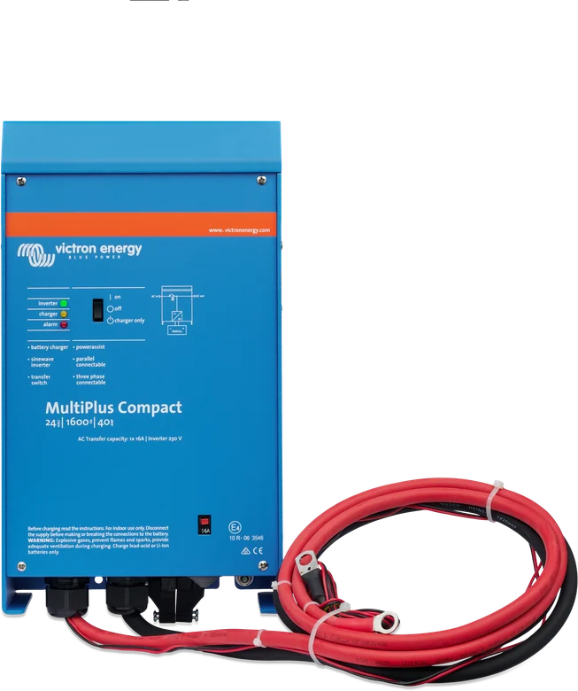
What is different about the Compact version?
Compact covers 800–2000 VA models: lighter (10–12 kg), with 16 A transfer (2000 VA — 30 A) and no second AC output. They also do not have the general-purpose port for BMS communication, which is fitted to the 3000 VA, 5000 VA and 20k models.
Can the MultiPlus handle a lithium battery?
The datasheet states compatibility with lithium-ion batteries, but only the 3000 VA, 5000 VA and 20k models have the general-purpose port for BMS communication. Charge voltages and current must be set according to the battery manufacturer’s documentation, and the battery must have a BMS compatible with the system.
What is the starter battery output for?
This is a second DC output with 4 A current and a slightly lower voltage — it keeps the starter battery in a vehicle or boat charged when the charger is running. Only the 12 V and 24 V models have it; the 48 V models do not.
MultiPlus or MultiPlus-II for energy storage?
For ESS installations that operate with the grid, the manufacturer directs you to the newer MultiPlus-II — it has built-in anti-islanding protection, an option for an external current transformer, and grid certifications. The classic MultiPlus is well suited where simple 230 V power supply matters: in a campervan, on a boat and in a cabin.
Devices that work with the MultiPlus

Manufacturer documentation
Document discrepancies: 3000 VA weight — datasheet 18 kg, manual 19 kg. AC input frequency of the charger — datasheet 45–65 Hz; specification table in the manual 45–55 Hz (factory setting in the same manual: 45–65 Hz). Power of 6 sets of 3 units — datasheet (range up to 5 kVA): 75 kW / 90 kVA and over 2,000 A; 3000 VA manual: 45 kW / 54 kVA and over 1,000 A. The EMC standard lists and the EN / EN-IEC 60335 wording also differ between the datasheet and the manual.
Content checked against Victron Energy documentation (datasheets and manuals) — as of 22 September 2026. Report a content error · Revision log