
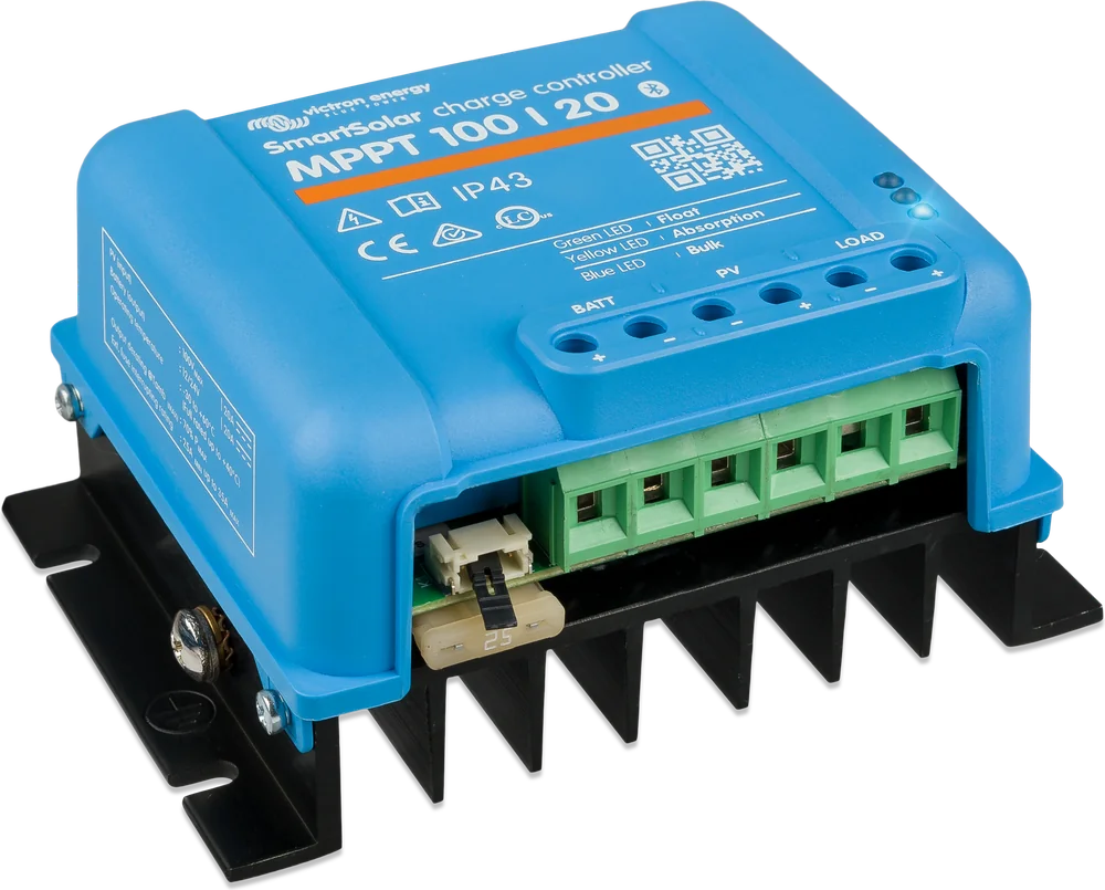
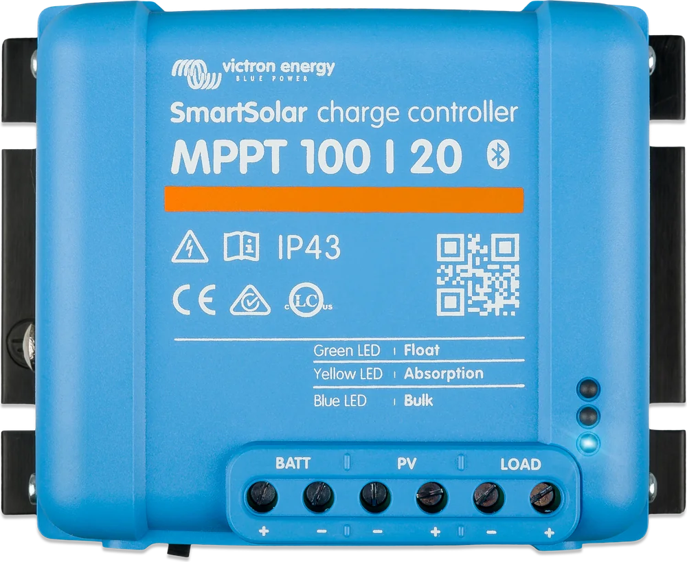
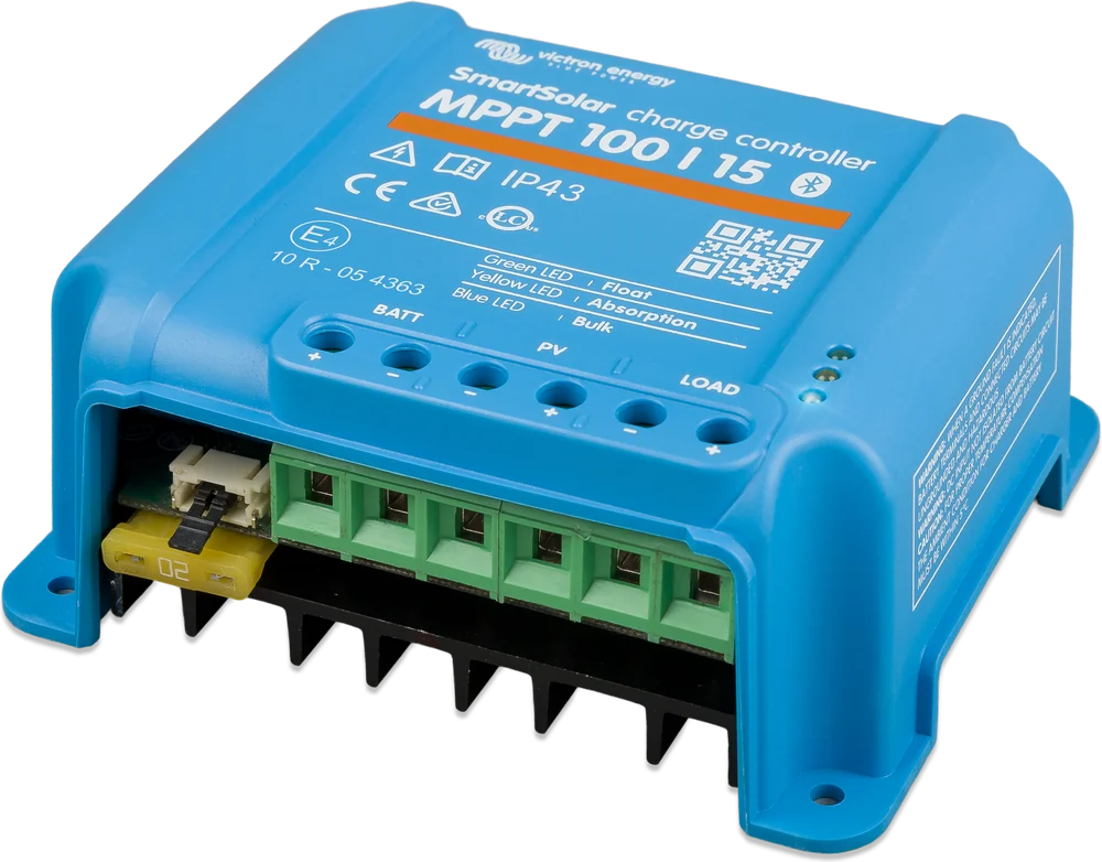
SmartSolar MPPT 100/20 — front view at an angle
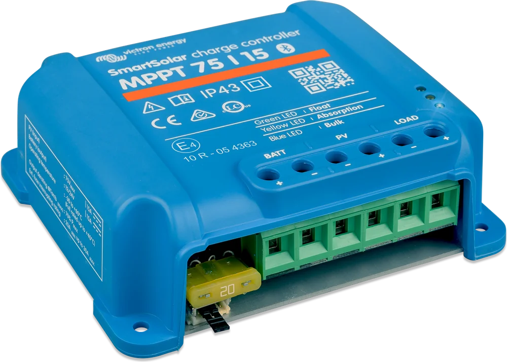
SmartSolar MPPT 75/10 – 100/20
Small charge controllers with built-in Bluetooth for photovoltaic panels. The most common choice for campervans, boats, cabins and small off-grid systems.
- 12 / 24 V (100/20: also 48 V)
- 75 V or 100 V PV
- 10–20 A
- Bluetooth
- VE.Direct
The bridge between the panels and the battery
A solar panel provides a voltage higher than the battery needs, and changes it with every cloud. The MPPT (Maximum Power Point Tracking) controller constantly looks for the point where the panel delivers the most power, and turns excess voltage into higher charging current.
According to the manufacturer, fast power point tracking gives up to 30% more energy than a PWM controller in variable cloud cover and up to 10% more than slower MPPT controllers.
- charges lead-acid, AGM, gel and lithium batteries (programmable algorithm),
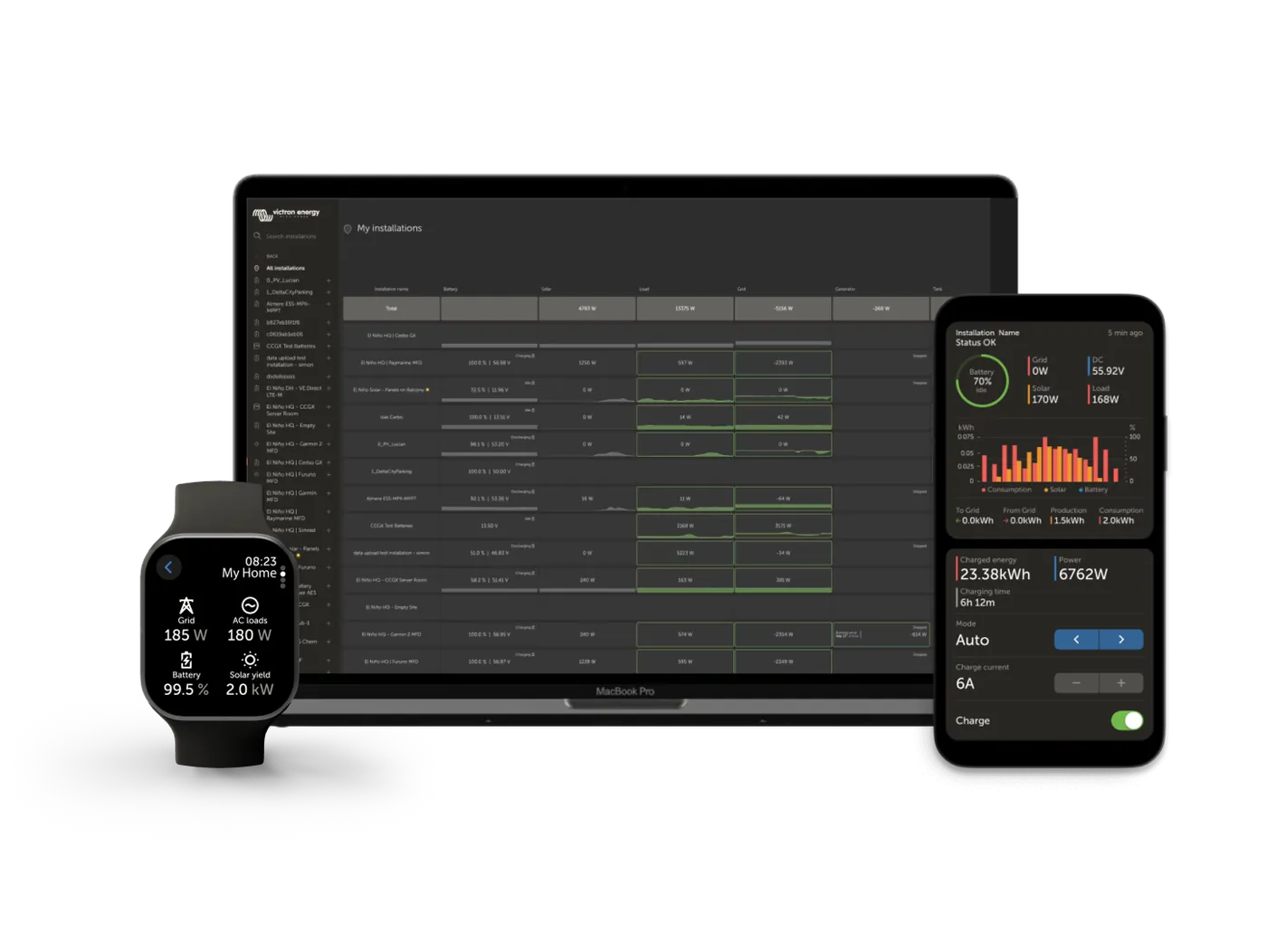
- view and settings on your phone via Bluetooth,
- dedicated load output protecting the battery from deep discharge.

Your phone instead of a display
You can see everything the controller does in the free VictronConnect app (Android, iOS, macOS, Windows). No cables and no additional panel — Bluetooth in your phone is enough. Exception: VictronConnect on Windows does not support Bluetooth — it connects only through the VE.Direct–USB interface.
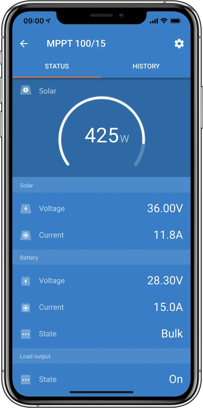
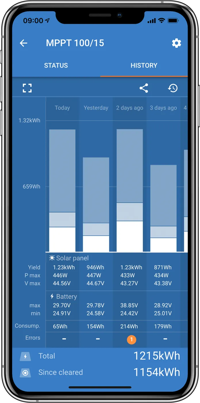
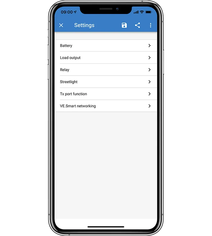
What SmartSolar MPPT can do
Fast MPPT tracking
It keeps up with changes in sunlight during passing clouds — that is when it gains the most over simpler controllers.
Load output
Loads connected to the LOAD terminal are disconnected when the battery falls to the set voltage (e.g. 11.1 V or 11.8 V at 12 V). The output is short-circuit proof.
BatteryLife
When there is not enough sun to fully charge the battery every day, the controller gradually disconnects the loads earlier — so that roughly once a week the battery reaches nearly 100%.
Temperature compensation
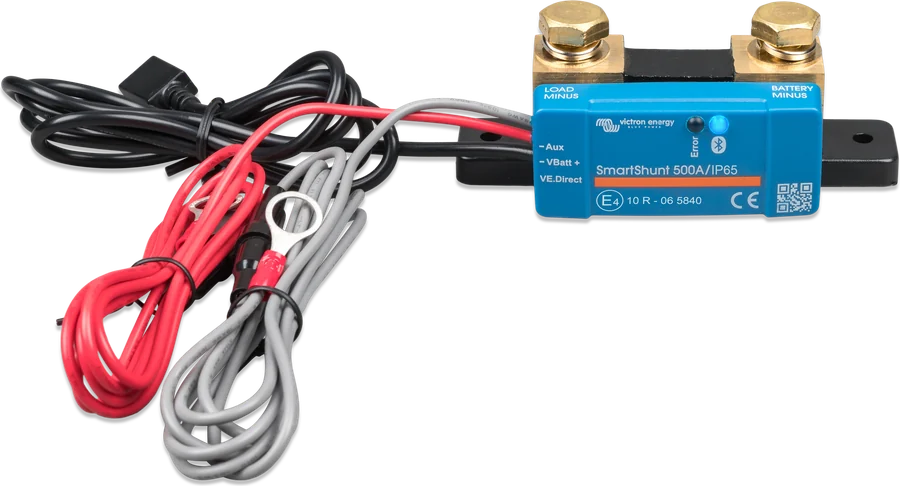
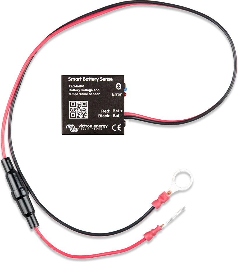
The built-in sensor corrects charging voltages (−16 mV/°C for 12 V). A more accurate measurement is provided by Smart Battery Sense (battery voltage and temperature) or BMV-712/SmartShunt (voltage; temperature only with an optional sensor) — they transmit data wirelessly via VE.Smart.
Rescue for a flat battery
It starts charging even a battery discharged to zero and reconnects to a lithium battery that has switched itself off.
History and VE.Direct
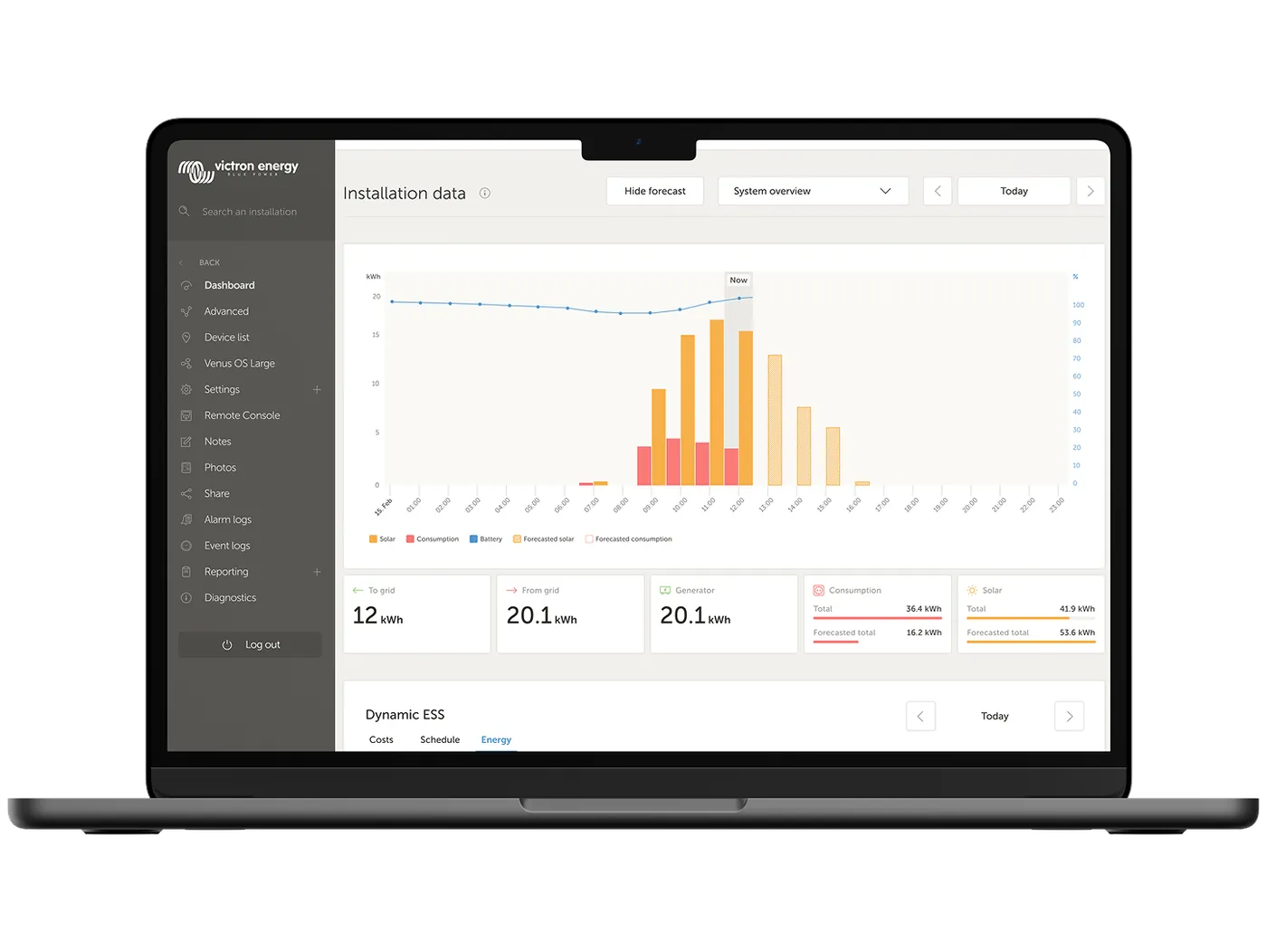
30-day daily history (yield, voltage minima and maxima) and 46-day trends (battery voltage, current and temperature, panel voltage and current). The VE.Direct port connects the controller to a GX device, computer or other device.
Four models — comparison
| Parameter | MPPT 75/10 | MPPT 75/15 | MPPT 100/15 | MPPT 100/20-48V |
|---|---|---|---|---|
| Battery voltage | 12/24 V | 12/24 V | 12/24 V | 12/24/48 V, 36 V manually |
| Charge current | 10 A | 15 A | 15 A | 20 A |
| Max. panel voltage (Voc) | 75 V | 75 V | 100 V | 100 V |
| Max. panel short-circuit current (Isc) | 13 A | 15 A | 15 A | 20 A |
| PV power at 12 V | 145 W | 220 W | 220 W | 290 W |
| PV power at 24 V | 290 W | 440 W | 440 W | 580 W |
| Panel power at 48 V | — | — | — | 1160 W |
| Load output (max.) | 15 A | 15 A | 15 A | 20 A (12/24 V), 1 A (36/48 V) |
| Weight | 0.5 kg | 0.5 kg | 0.6 kg | 0.65 kg |
| Dimensions (H × W × D) | 100 × 113 × 40 mm | 100 × 113 × 40 mm | 100 × 113 × 50 mm | 100 × 131 × 60 mm |
“Nominal” panel power is the value at which the controller delivers full charge current. You can connect more — the controller will then limit the input power. However, you must not exceed the maximum Voc voltage or the Isc short-circuit current — this can damage the controller. Note: for the 75/10, the manufacturer’s sources disagree — the datasheet gives 13 A, while the technical manual gives 10 A. The 100/20 model with a 36 or 48 V battery has a load output of only 1 A — enough to drive a relay. For larger panels, choose a controller from the SmartSolar 150 V and 250 V range, and for large 48 V systems with long panel strings — the SmartSolar MPPT RS 450.
- Peak efficiency
- 98%
- Charging algorithm
- multi-stage, adaptive
- Absorption / float (12 V, default)
- 14.4 / 13.8 V (adjustable)
- Start charging
- when PV voltage > battery + 5 V
- Operating temperature
- −30 … +60 °C (full current up to 40 °C)
- Terminals
- up to 6 mm² (AWG10)
- Ingress protection
- IP43 electronics, IP22 terminals
- History in memory
- 30 days (daily), 46 days (trends)
How to choose a controller — three steps
Voc in frost < limit
Add up the Voc of the panels connected in series and convert it to the lowest temperature using the coefficient from the panel datasheet. The result must be below 75 V or 100 V — Victron recommends at least 10% headroom.
2 × 37 V × (1 + 45 × 0.35%) ≈ 85.7 V → 100 VSum of Isc ≤ limit
With panels connected in parallel, the currents add up. The sum of Isc must not exceed 13–20 A (depending on the model).
1 × 11.5 A < 20 A → OKPanel power ≈ nominal
With a 12 V battery, the 100/20 model will use about 290 W of panels. More power will not cause damage, but it will be clipped at midday.
2 × 400 W at 24 V → 100/20 will give about 580 WA 400 W panel with Voc 37 V and a −0.35%/°C coefficient (check your nameplate — 72-cell panels have a Voc of about 45–50 V). Two in series give 74 V — in the catalogue that does not exceed 75 V, but at −20 °C it will rise to about 86 V. You need a 100 V controller. At 12 V, the 100/20 model will deliver a maximum of 20 A, i.e. about 290 W — with 800 W of panels it is better to use a larger controller (e.g. 100/50) or switch to 24 V.
The figures above are examples. The open-circuit voltage of panels (Voc) rises when the temperature falls below 25 °C — by the percentage per degree given by the Voc temperature coefficient in the panel datasheet. For Victron BlueSolar panels (−0.35%/°C), at −20 °C this is about 16% more than in the catalogue. Victron recommends leaving at least 10% voltage headroom and, in a cold climate, recalculating Voc for the lowest expected temperature. Calculate it in the MPPT calculator.
How to connect SmartSolar MPPT
Panels to controller, controller to battery, small loads to the LOAD output. Hover over a diagram element or tap it to see the description. The PV input is not isolated from the battery circuit — the PV, battery and control circuits are treated as hazardous and should not be accessible to the user. Cover the PV and battery terminals to prevent accidental contact; mount the controller in an enclosure or use the optional WireBox.
- PV panels → PV terminalsString Voc with frost margin below 75/100 V.
- Controller → batteryAlways through a fuse, close to the battery. Connect the battery first.
- LOAD output → DC loadsCompatible with system voltage; for the 100/20 in a 36/48 V system, only 1 A.
- Smart Battery SenseSends battery voltage and temperature wirelessly.
- VE.Direct → Cerbo GXOptional: view in the GX device and VRM portal.


What to watch out for when connecting
The controller detects the battery voltage (12 or 24 V) only at first start-up. Connection order according to the manual: battery → wait 10 s and check the system voltage in VictronConnect → DC loads → panels → VE.Direct. Before connecting PV, cover the panels from light, do not touch bare wire ends and use only insulated tools. Panels may only be connected first if the system voltage is set manually. A 36 V battery is always set manually.
Protect the cable from the controller to the battery with a fuse as close to the battery as possible — even if the controller has an external fuse: 75/10 — 15–20 A, 75/15 and 100/15 — 20–25 A, 100/20 — 25–30 A.
On a non-combustible surface, with at least 10 cm of free space above and below the housing, up to 3 m from the battery, but never directly above it. For correct temperature compensation, the difference between the controller and battery ambient temperatures should not exceed 5 °C. With larger differences, use direct battery temperature measurement. Install the 100/15 model in a suitable fire-resistant enclosure in accordance with IEC 62109-1 and local requirements. The terminals accept cables up to 6 mm²; use flexible stranded copper cables (single strand max. 0.4 mm or 0.125 mm²) and tighten to 0.75 Nm.
Do not connect panels with optimisers — they can permanently damage the controller. Provide a way to disconnect the panels (PV isolator). Do not connect an inverter to the LOAD output — connect it only directly to the battery.
The default voltages (14.4 / 13.8 V) suit many batteries, but for LiFePO4 choose the appropriate profile and check the voltages in the battery documentation.
LEDs and most common errors
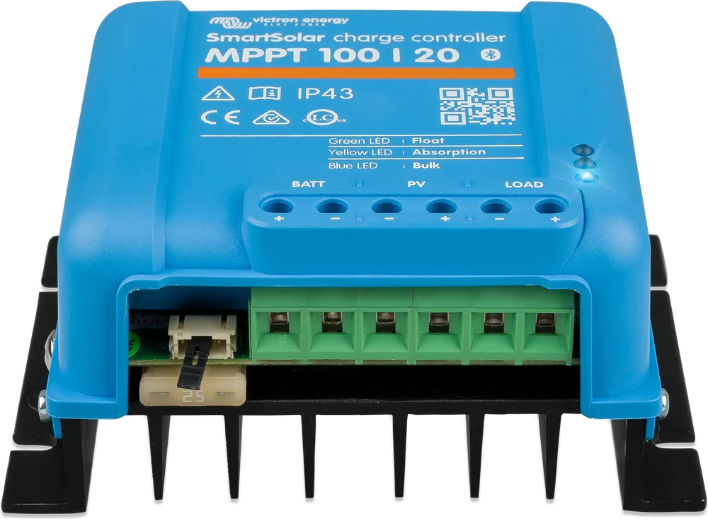
The controller has no display — status and faults are shown by three LEDs and in the app. Below are the signals that occur most often; the full list is in the charger and MPPT error codes section.
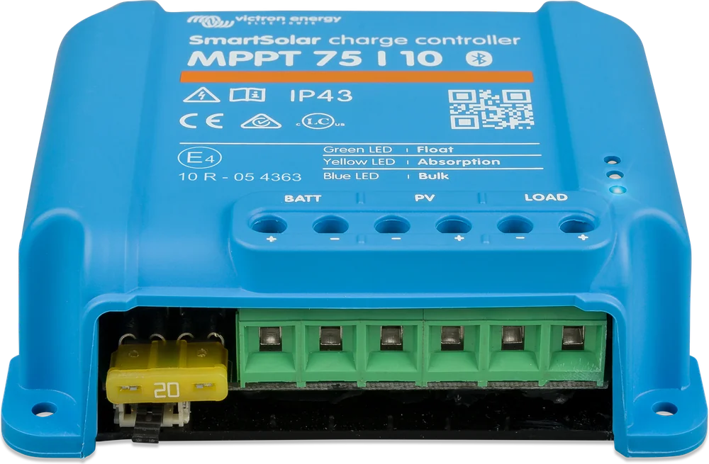
Three LEDs: Bulk, Absorption, Float
They show the charging stage, and in the event of a fault they flash an error code. The combinations are described by the LED decoder, and you can see the exact error number in the VictronConnect app.
The controller does not start charging
Charging only starts when the panel voltage exceeds the battery voltage by 5 V. Also check the PV isolator, polarity and whether the panels are shaded. Step by step: MPPT is not charging.
Err 2 — battery voltage too high
The voltage at the terminals has exceeded the permissible level. Check the other charging sources and the selected battery type.
Err 17 — controller overheating
The device limits the current, yet it is still too hot. Ensure vertical mounting, terminals facing down, and 10 cm of free space above and below the casing.
Err 26 — overheated terminals
Usually a loose connection or a cable that is too thin. The terminals accept up to 6 mm² and are tightened to 0.75 Nm.
Err 33 — PV input overvoltage
The array voltage has exceeded the permitted 75 or 100 V. Recalculate the string Voc with a frost margin in the MPPT calculator.
Err 11 — high battery voltage ripple
Most often loose terminals or battery cables that are too thin. Check the tightening and cable cross-sections.
Err 119 — settings lost
The controller cannot read the configuration. Restore the factory settings and configure it again in VictronConnect.
Frequently asked questions about SmartSolar MPPT
Does MPPT really pay off more than a cheap PWM controller?
For small systems with a single 12 V panel, the difference can be small. MPPT gives the biggest gain when panel voltage is clearly higher than battery voltage (for example, two panels in series) and in changing cloud cover — the manufacturer states up to 30% more energy than PWM. You also get Bluetooth, history, and integration with the rest of the Victron system.
Can I connect more panels than the stated “nominal power”?
Yes — the controller will limit the power and some energy will be wasted at sunny midday, but you will gain in the morning, evening and on cloudy days. However, you must not exceed the maximum Voc voltage (75/100 V) or the Isc short-circuit current.
I have two different panels. Can I connect them to one controller?
Connecting different panels in one string reduces yield — the current is determined by the weaker panel. It is better to give each panel (or group of identical panels) its own controller. Several SmartSolar controllers can charge the same battery and synchronise wirelessly via VE.Smart Networking.
Does SmartSolar charge lithium batteries?
Yes. In the app you select the profile for LiFePO4 or set the voltages manually. With lithium batteries, the system should have a BMS that can stop charging when needed — in Victron systems the controller can be controlled by it, for example via a GX device.
What does Smart Battery Sense do if the controller measures voltage?
The controller measures the voltage at its terminals — at high current it is higher than at the battery because of the voltage drop on the cables. Smart Battery Sense measures voltage and temperature directly at the battery and sends them wirelessly, which makes charging more accurate.
What is the LOAD output and BatteryLife mode for?
DC loads are connected to the LOAD terminal — the controller disconnects them when battery voltage falls to the set threshold (for example 11.1 or 11.8 V in a 12 V system), and reconnects them after charging. BatteryLife goes one step further: when there is not enough sun, it disconnects the loads earlier from day to day so that the battery reaches full charge roughly once a week. An inverter must not be connected to LOAD — only directly to the battery.
In what order should I connect the cables?
Battery → 10-second pause and check the system voltage in the app → DC loads → panels → VE.Direct. The controller recognises battery voltage only on first start-up; a 36 V battery is always set manually. Before connecting the panels, shield them from light.
Which fuse and how far from the battery?
Fit the fuse as close to the battery as possible: 15–20 A for 75/10, 20–25 A for 75/15 and 100/15, and 25–30 A for 100/20. Mount the controller vertically, terminals facing down, up to 3 m from the battery, but never directly above it; the temperature difference between the controller and the battery should not exceed 5 °C.
Can I connect to the controller from a computer?
Yes, but VictronConnect on Windows does not support Bluetooth — you need a VE.Direct–USB interface. On Android, iOS and macOS, Bluetooth is enough. The controller is also connected to a GX device and the VRM portal through the same VE.Direct port.
Devices it works with most often

Manufacturer documentation
- SmartSolar MPPT 75/10 – 100/20 datasheetPDF · EN
- Overview of all BlueSolar and SmartSolar controllersPDF · EN
- Product page on the manufacturer’s website (manuals, certificates)victronenergy.com
We prepared this description independently based on the manufacturer’s documentation. If there are any discrepancies, the current Victron Energy documentation is binding. You can report an error here.
Content checked against Victron Energy documentation (datasheets and manuals) — as of 19 September 2026. Report a content error · Revision log