
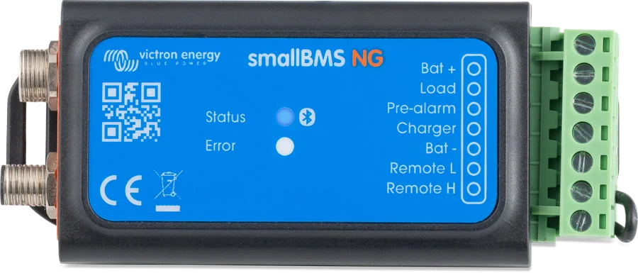
smallBMS NG — labels for Bat +, Load, Pre-alarm, Charger, Bat −, Remote L and Remote H outputs
smallBMS NG
Compact BMS with pre-alarm intended only for Lithium NG batteries. According to the manufacturer, this is a simple and economical alternative to VE.Bus BMS NG — without a VE.Bus interface. It controls chargers and loads through Charge disconnect and Load disconnect outputs; it has Bluetooth and automatically detects connected batteries.
- 12 / 24 / 48 V
- up to 50 batteries (48 V: 25)
- Bluetooth
- Load / Charge disconnect
- pre-alarm
The simplest way for an NG battery to have its own BMS
Lithium NG batteries do not disconnect anything themselves — they measure and send data, and the BMS makes the decisions. smallBMS NG is the smallest of them: instead of a contactor it has three control outputs, which switch off loads, stop chargers and trigger the warning signal.
Suitable for installations without a VE.Bus inverter, where control of chargers and loads via their remote inputs or via Smart BatteryProtect is sufficient. Configuration and monitoring via Bluetooth in the VictronConnect app.
- 12, 24 and 48 V systems — up to 50 batteries per BMS (up to 25 at 48 V),
- three outputs: Load disconnect, Charge disconnect and pre-alarm,
- 3 mA operating current and 1.2 mA when switched off — it can be left connected.

What smallBMS NG can do
Load disconnect
Normally high, floating when the cell voltage is too low; load capacity up to 1 A. Controls remote inputs of inverters, BatteryProtect and DC-DC converters.
Charge disconnect
Normally high, floating on cell overvoltage or wrong temperature; up to 500 mA, no short-circuit protection. Do not use it to control a relay coil.
Pre-alarm with time reserve
Turns on at least 30 seconds before the loads are disconnected — that is the time left to react. The output powers a buzzer or lamp.
Discharge floor
The minimum state of charge at which the BMS switches off loads and raises an alarm. The manufacturer treats cut-off by cell voltage as a last resort — it is better to shut down the system by this threshold or by the Remote input.
Bluetooth and VictronConnect
View battery status, alarms and codes, and change settings on your phone. Capacity, voltage and the number of batteries are recognised automatically.
Remote L / H input
Main system switch: when switched off, both outputs become floating, so chargers and loads stop.
Up to 50 batteries
One BMS handles up to 50 Lithium NG batteries in 12 and 24 V systems, and up to 25 at 48 V. The batteries are connected to it in a chain with BMS cables.
It also monitors temperature
The message “Allowed to charge: No” appears, among other cases, when battery temperature is below 5 °C, when it is too high, or after the high cell voltage threshold has been reached.
What it controls and how
| Terminal | Operation | What it is for |
|---|---|---|
| Load disconnect | normally high (battery voltage − 0.1 V), floating when cell voltage is too low; up to 1 A, no short-circuit protection | remote input for BatteryProtect, inverters, DC-DC converters; heavy-duty relay or contactor |
| Charge disconnect | normally high, floating on cell overvoltage or incorrect temperature; up to 500 mA, no short-circuit protection | remote input for chargers (for example Smart IP43 — to terminal H), Cyrix-Li-Charge, Cyrix-Li-ct, BatteryProtect. Do not connect to a relay coil or any other inductive load. |
| Pre-alarm | normally floating, on alarm battery voltage − 0.1 V; at least 30 s before load cut-off; no short-circuit protection | buzzer, lamp |
| Remote L / H | on: L–H shorted; L to minus (< 3.5 V); H between 2.9 V and battery voltage; off in other conditions | system switch — when switched off, both outputs become floating |
Pre-alarm output load rating: datasheet and manual tables state 500 mA, while the function description states 1 A; it is safer to assume 500 mA. VE.Direct and Inverter Smart inverters are controlled directly from Load disconnect (the H terminal of their remote connector). VE.Bus and Inverter Compact inverters from 1200 VA require the “inverting remote on-off” cable (ASS030550100 or -120). SmartSolar up to 150/35 and BlueSolar MPPT (except 150/70 and 150/80 CAN-bus) require the VE.Direct “non-inverting remote on-off” cable (ASS030550320).
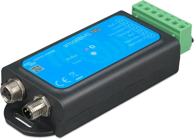
smallBMS NG, VE.Bus BMS NG or Lynx Smart BMS NG
smallBMS NG
Three control outputs and pre-alarm, without contactor. For smaller installations where chargers and loads have their own remote inputs.
12/24/48 V · up to 50 batteriesVE.Bus BMS NG
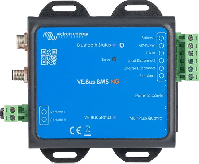
Controls the inverter or inverter/charger directly via VE.Bus, and the rest via control outputs. VE.Bus BMS NG datasheet.
VE.Bus + outputsLynx Smart BMS NG
A contactor that disconnects the whole DC system, built-in battery monitor and VE.Can to GX device — for yachts and larger installations. Lynx Smart BMS datasheet.
500 or 1,000 A contactorHow to connect smallBMS NG
The BMS controls chargers and loads via the Charge disconnect and Load disconnect outputs, and the pre-alarm warns at least 30 s before cut-off. The Bat+ terminal must have its own fuse. Wiring overview.
- Remove the remote loopSo the system does not switch on during installation.
- BMS cables in a chainTwo free ends to the BMS; extend only with M8 3-pin cables from the NG range.
- Bat+ via fuseRecommended 0.3–2.5 A, depending on the devices on the outputs.
- Control outputsCharge disconnect → chargers, Load disconnect → BatteryProtect and inverters.
- Minus battery endThen fit the remote loop or a switch between L and H.
Sequence according to the manual
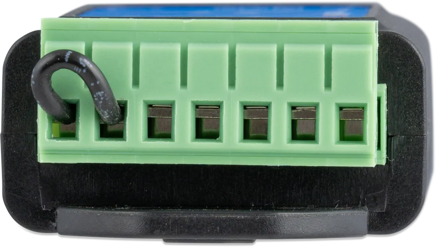
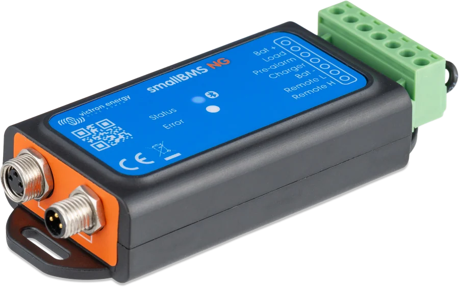
- Best mounted on a flat surface. Before installation, remove the loop from the remote terminals so the system does not switch on by accident.
- Connect the cables and fuses. The Bat+ terminal must have a fuse (not included) — recommended 0.3–2.5 A, depending on the devices connected to the Load disconnect and pre-alarm outputs. Leave the battery minus disconnected until the end of installation.
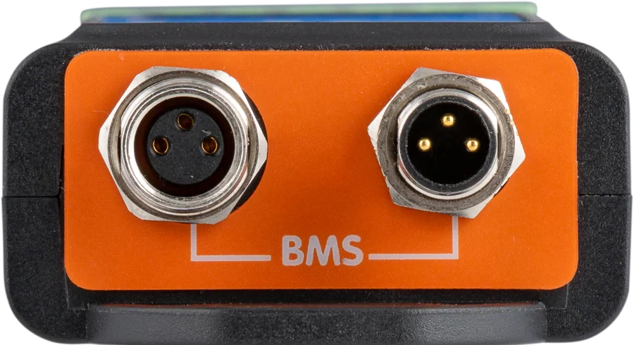
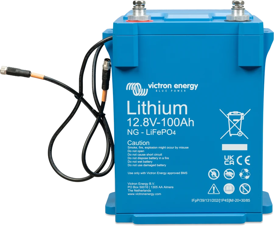
- Connect the battery BMS cables in a chain, then connect the two free ends to the BMS; extend only with M8 (3-pin) cables from the NG range.
- Fit the loop back onto the Remote L and H terminals, or install a switch between them (or control terminal H or L with a signal).
- Finally connect battery minus. For first start-up, Bat+ and Bat− on the 7-pin connector must be connected to the battery, and remote must be enabled.
- Installation must be carried out by qualified installers, strictly in accordance with national safety regulations, after reading the manuals for all connected devices. Before changing connections, switch off the system and check that there is no dangerous voltage.
- Do not open a lithium battery, do not install it upside down, and do not install it in a living area; ensure ventilation; do not discharge a new battery before its first full charge.
- Chargers and loads not controlled by the BMS (ATC and ATD) can permanently damage the battery.
- After cut-off due to low cell voltage, about 1 Ah remains per 100 Ah of capacity. According to the manual, even 10 mA of residual current can damage a 200 Ah battery if the system remains discharged for more than 8 days — the battery must be charged immediately, and if there is any doubt about leakage, disconnect it (switch, remove the fuse or disconnect the positive).
Discharge floor and currents
- Discharge floor — the minimum SoC at which the BMS immediately switches off the ATD output (loads) and raises a low SoC alarm. Setting it to 0 disables the function — the manufacturer does not recommend this. The manual treats cut-off by low cell voltage as a last resort — it is better to shut the system down using the discharge floor or remote.
- The low SoC warning activates the pre-alarm and a message in VictronConnect; the pre-alarm level is adjustable.
- Capacity, voltage and number of batteries are recognised automatically (you cannot change them, but you must check them). Tail current is set to 4% by default, charge detection time to 3 min (both adjustable).
- Lithium NG battery currents: max. 1C continuous, recommended 0.3C for charging (according to the BMS manual; the Lithium NG battery manual itself recommends 0.5C) and 0.5C for discharging; discharge pulse 2C for up to 10 s.
- “Allowed to charge: No” appears, among other cases, when battery temperature is below 5 °C or too high, or when the cells have reached the high voltage threshold.
- Updates: the manufacturer advises against updating a working system unless there are problems or the update is being done before first commissioning. During the update, Charge disconnect opens; after a failed update, Load disconnect opens after 120 s.
- If the balancer status is unknown (no full charge for more than 30 days, new battery, unknown SoC) or cell imbalance has been detected, carry out a full charge cycle.
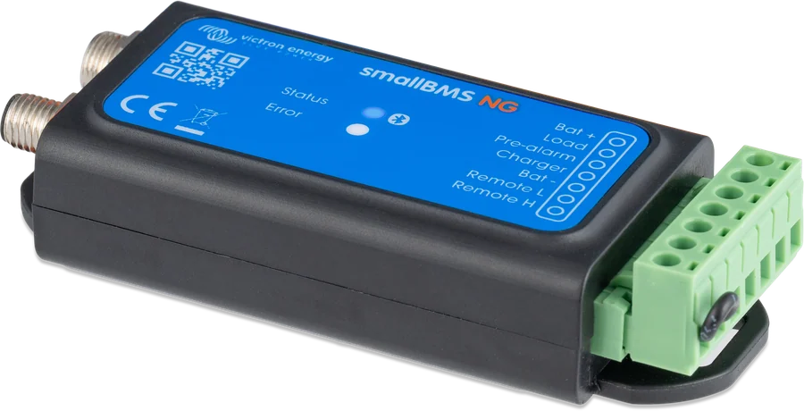
LEDs and codes
The BMS has two LEDs, and the details — code and description — are shown in the VictronConnect app. All codes with descriptions: smallBMS NG and VE.Bus BMS NG error codes.
Blue on
Active Bluetooth connection with the VictronConnect app.
Blue flashing
The BMS is operating, but is not connected to a phone.
Blue off
No power or Bluetooth is off. To restore it: switch the BMS off and on — for about 30 seconds Bluetooth is available, and during that time you can enable it permanently in the product information.
Red flashing or on
Flashing is a warning, steady light means an alarm or error. You can see the code in the app.
W-B01 / A-B01 — low cell voltage
Warning, then load disconnect. Charge the battery as soon as possible.
W-B05 — battery communication lost
Check the BMS cables and their connection in the battery chain.
W-B07 — low state of charge
This triggers a pre-alarm and a message in the app; the pre-alarm level is adjustable.
A-B09 and A-B13 — temperature
Temperature too high or too low for charging. The message “Allowed to charge: No” appears, among other cases, below 5 °C.
E-B01 / E-B05 — incorrect battery configuration
Check the number and type of batteries connected, and the BMS chain connections.
E-B09 — voltage outside range
System voltage has fallen below 9 V or exceeded 60 V.
E-B36, E-B11, E-B116 — faults
In order: ATC/ATD output fault, hardware fault, and loss of calibration. Contact your dealer.
E-B119 — settings lost
Restore the default settings and configure the BMS again. After a failed cell module update (W-B11), perform a power cycle.
smallBMS NG FAQs
Which batteries is smallBMS NG suitable for?
Only Lithium NG batteries. For Lithium Smart batteries, use VE.Bus BMS V2 or smallBMS (non-NG).
How does it differ from VE.Bus BMS NG?
It has no VE.Bus interface, so it does not control the inverter/charger via the bus — it controls everything through the Charge disconnect and Load disconnect outputs. It is a simpler and cheaper alternative for smaller systems.
What fuse should be fitted on the Bat+ terminal?
Recommended 0.3–2.5 A, depending on the devices connected to the Load disconnect and pre-alarm outputs. The fuse is not included.
How much current can the control outputs handle?
Load disconnect up to 1 A, Charge disconnect up to 500 mA — both without short-circuit protection. For the pre-alarm output, the datasheet specifies 500 mA, while the function description says 1 A, so it is safer to assume 500 mA. Do not connect a relay coil or any other inductive load to the outputs.
How do you switch off the entire system?
With a switch between the Remote L and H terminals (or by removing the factory loop). When switched off, both control outputs become free, so chargers and loads are disconnected.
What does the “discharge floor” setting do?
It is the minimum state of charge, after which the BMS switches off the loads and raises an alarm. Setting it to zero disables this protection — the manufacturer does not recommend this, because cell-voltage cut-off is meant to be the last resort.
At what current should you charge the batteries in such a system?
The BMS manual states a maximum of 1C in continuous operation, recommended 0.3C for charging and 0.5C for discharging, and a 2C discharge pulse for up to 10 seconds. The Lithium NG battery manual itself recommends 0.5C for charging — use the lower value.
Should you update the software of a working system?
The manufacturer does not recommend updating a working system unless there are problems or you are doing it before first commissioning. During the update, Charge disconnect opens, and after a failed attempt — after 120 seconds, Load disconnect also opens.
When should you perform a full charge cycle?
When the balancer status is unknown — after more than 30 days without a full charge, with a new battery, or with unknown state of charge — and also when the BMS detects cell imbalance.
Manufacturer documentation
Content checked against Victron Energy documentation (datasheets and manuals) — as of 19 September 2026. Report a content error · Revision log