
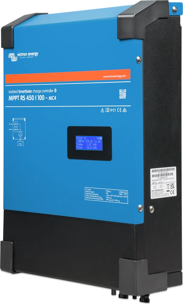
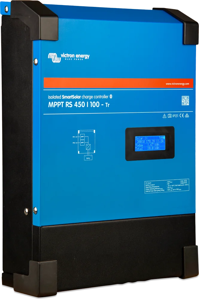
SmartSolar MPPT RS 450/100 MC4 — angled view
SmartSolar MPPT RS 450
Solar charge controller for large installations with a 48 V battery. It accepts long PV strings up to 450 V, has 2 or 4 independent MPPT inputs, and full galvanic isolation between the panels and the battery.
- 48 V battery
- up to 450 V PV
- 100 / 200 A
- 2 / 4 trackers
- isolated
- VE.Can · Bluetooth
Large PV array, thin cables
SmartSolar controllers accept 75 to 250 V from the panels (see 75/10–100/20 and 150/250 V). With a large installation this means many short strings connected in parallel and thick cables. The MPPT RS accepts up to 450 V, so around 10–11 typical panels can be connected in series in one string (manufacturer example: 11 panels, 404 V).
Higher voltage means lower current for the same power: 4000 W at 400 V is only 10 A, while at 40 V it would be 100 A. This means the panels can be far from the room with the battery bank — on the barn roof or on the ground behind the house — without huge cable cross-sections.
- 48 V batteries only — for home energy storage and large off-grid systems,
- 2 or 4 independent MPPT inputs — each string works separately,
- for off-grid and grid-connected systems (ESS); display, Bluetooth and VE.Can.
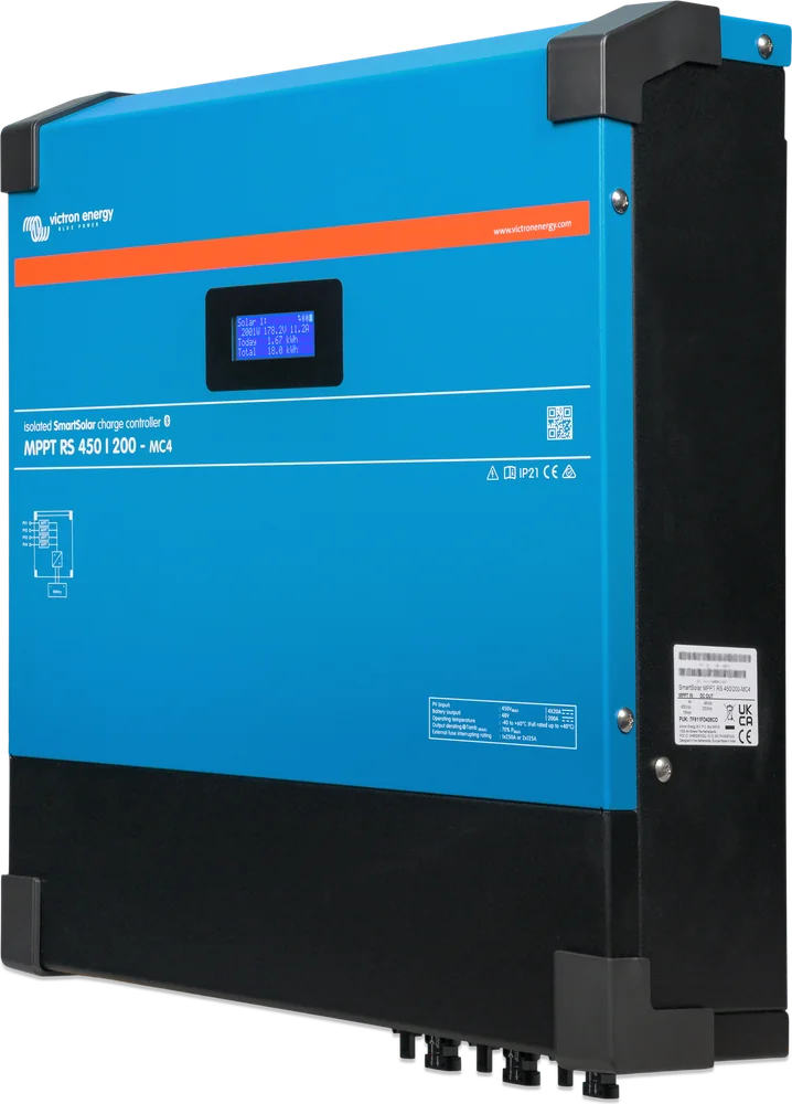

What makes the MPPT RS stand out
Independent trackers
2 MPPT inputs in the 450/100 model and 4 in the 450/200 model. A separate PV array is connected to each one (it may have several parallel strings within the input current limit), and the tracker converts its energy into charging (max. 4000 W).
Galvanic isolation
The PV side is completely isolated from the battery side — high voltage from the panels cannot reach the 48 V installation.
PV isolation monitoring
The controller continuously measures the resistance between PV+ and earth and between PV− and earth. Below 100 kΩ it reports a fault — also to the GX device, with an alarm and email — and continues charging.
Display and Bluetooth
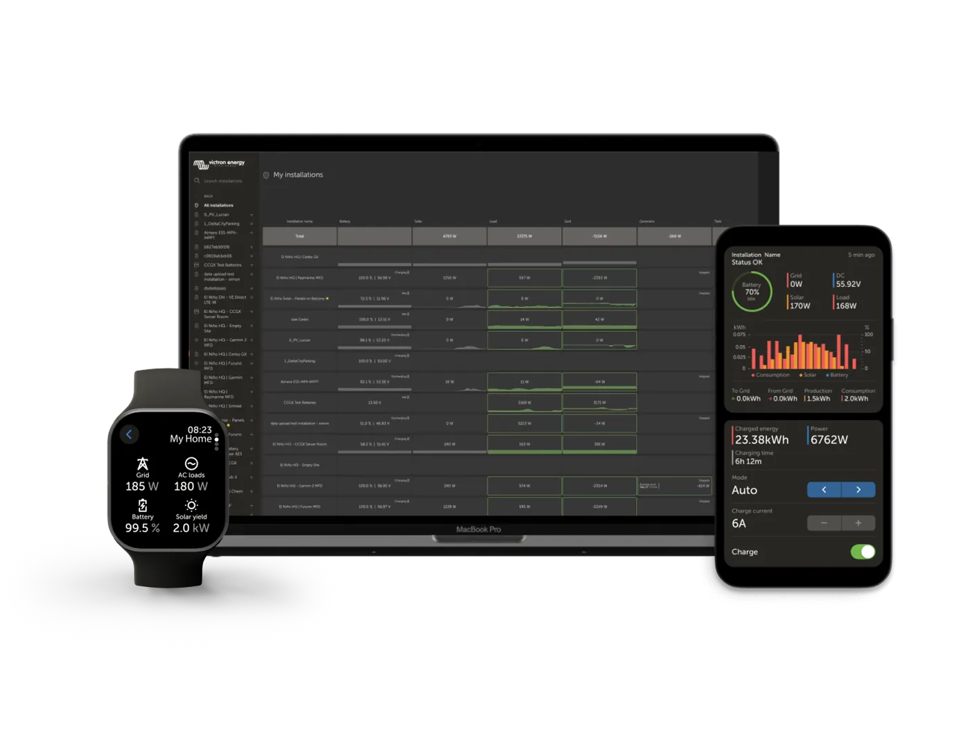
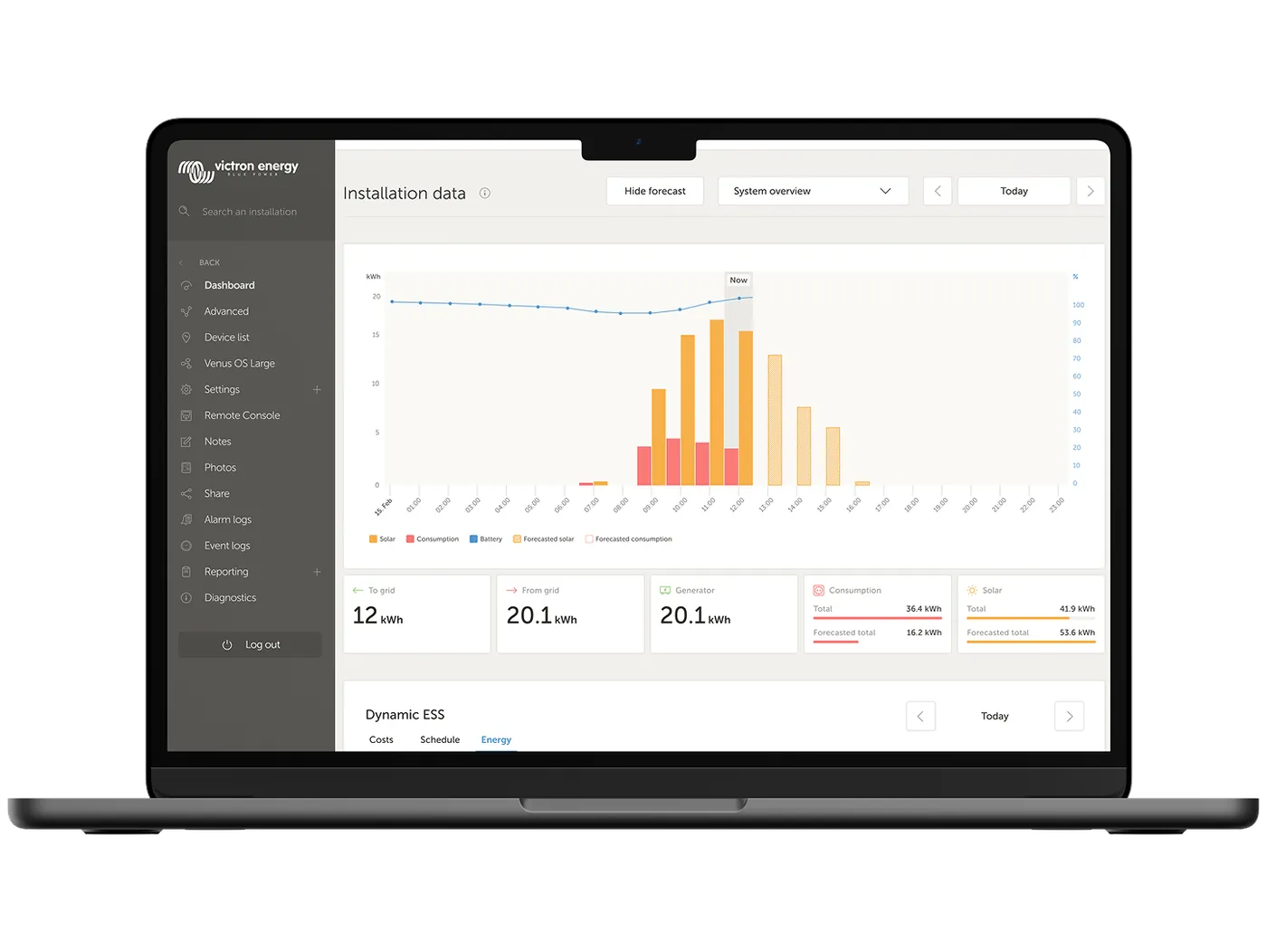
On the display: battery voltage, charging current, each input’s voltage and fault codes. In VictronConnect: settings and 30-day history separately for each tracker.
Parallel operation
Up to 25 controllers connected by VE.Can cable (RJ45) synchronise charging stages. Each controller must have its own panels.
Inputs and relay
Programmable relay (alarm, low voltage, generator start/stop), 2 analogue/digital inputs, remote on/off with BMS “allow-to-charge” signal. Battery temperature sensor included.
450/100 or 450/200
| Parameter | MPPT RS 450/100 | MPPT RS 450/200 |
|---|---|---|
| Battery voltage | 48 V | 48 V |
| Charge current | 100 A | 200 A |
| Max. charging power | 5760 W | 11 520 W |
| Number of MPPT trackers | 2 | 4 |
| Charging power per tracker | 4000 W | 4000 W |
| Max. PV voltage | 450 V | 450 V |
| MPPT start voltage / operating range | 120 V / 65–450 V | 120 V / 65–450 V |
| Operating current per tracker | 16 A | 16 A |
| Max. short-circuit current (Isc) per tracker | 20 A | 20 A |
| Max. PV power per tracker | 7200 Wp | 7200 Wp |
| Battery connections | 2 × M8 (1 positive, 1 negative) | 4 × M8 (2 positive, 2 negative) |
| Weight | 7.9 kg | 13.7 kg |
| Dimensions (H × W × D) | 440 × 313 × 126 mm | 487 × 434 × 146 mm |
7200 Wp per tracker comes from the fact that with Voc 450 V the string operating voltage is about 360 V, and 360 V × 20 A = 7200 W. Charging power from one input is limited to 4000 W, so the extra panels help in the morning, in the evening and on cloudy days. Operating current: the datasheet gives 16 A per tracker, the manual 18 A — design to the lower value.
Tr and MC4 versions
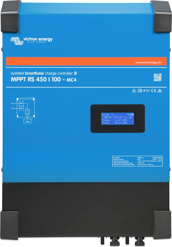
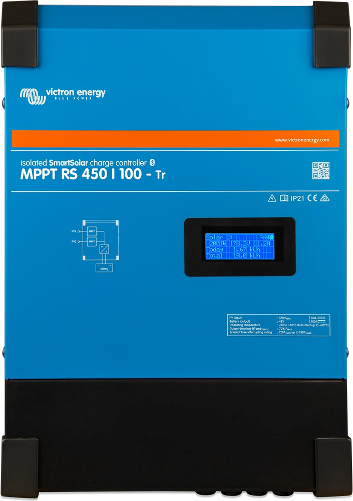
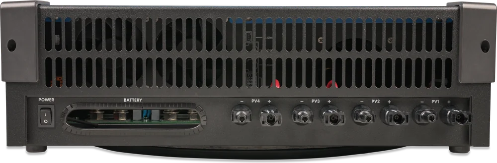
- Absorption / float (default)
- 57.6 / 55.2 V (adjustable)
- Voltage setting range
- 36–60 V for absorption and float; terminal voltage may be higher because of temperature and cable drop compensation. Above 60 V the current decreases linearly to 5 A at 62 V, and equalisation can be set up to 62 V
- Maximum efficiency
- 96%
- Self-consumption
- 15 mA
- Communication
- Bluetooth and wired VE.Can or VE.Direct — for wired connection, use only one type of port at a time
- Parallel operation
- up to 25 units (VE.Can, identical settings, bus terminators)
- Relay
- 4 A up to 35 V DC, 1 A up to 70 V DC
- Operating temperature
- −40 … +60 °C (full power up to 40 °C); recommended ambient temperature for installation −20 … +40 °C
- Enclosure
- steel, IP21
- Battery temperature sensor
- included
Four conditions for string sizing
The method for calculating panel voltage with frost margin is the same as for small controllers — we described it in the SmartSolar MPPT card. With this controller, do not use panels with optimisers, because their own tracking circuitry interferes with the controller’s MPPT algorithm. With the MPPT RS, two additional conditions apply: minimum start voltage and a limit based on battery voltage.
Voc < 450 V
String voltage on the coldest day. The manufacturer recommends at least 10% margin and the calculator on the product page. Overvoltage damages the controller and is not covered by the warranty.
Voc < 8 × float
At 55.2 V float this gives 441.6 V, at 54.0 V — 432 V, at 52.8 V — 422.4 V. If exceeded, the controller reports “Over-charge Protection” and switches off.
Start from 120 V
The controller starts when panel voltage exceeds 120 V, and then operates from 65 V. A short string of a few panels may not be enough.
16 A / 20 A
Operating current up to 16 A per input (datasheet; the manual states 18 A — design to the lower value), short-circuit current Isc up to 20 A. 20 A is the reverse-polarity protection limit: with correct connection the absolute maximum is 30 A, but reverse connection of an array above 20 A risks damage. One PV array per input — do not connect the same array to two trackers.
400 W panel with Voc 37.5 V and Isc 13.5 A. 10 panels in series: 375 V, with 10% headroom about 413 V — stays below 441.6 V (8 × float 55.2 V) and below 450 V. 11 panels: 412.5 V, with headroom about 454 V — too much. A 10 × 400 W string = 4000 Wp, exactly what one input can convert for charging. In the 450/200 model, four such strings are 16 kWp — the controller will deliver up to 11.52 kW, and in sunny midday it will clip the surplus.
The “8 × float” rule depends on the set float voltage. If you set a lower voltage for a LiFePO4 battery, the permissible string Voc also drops — calculate it for your own settings before deciding how many panels to use.
From panel strings to 230 V sockets
Example of a 48 V home system with energy storage. Hover over a schematic element or touch it to see the description.
- Panel stringsEach string to a separate MPPT input (2 on the 450/100, 4 on the 450/200).
- DC isolator ≥ 450 VMandatory — the controller has no built-in isolator. DC-rated switches only.
- MPPT RS 450Galvanically isolated, it tracks the maximum power point of each string separately.
- 48 V battery via fuse125–150 A (450/100) or 250 A (450/200).
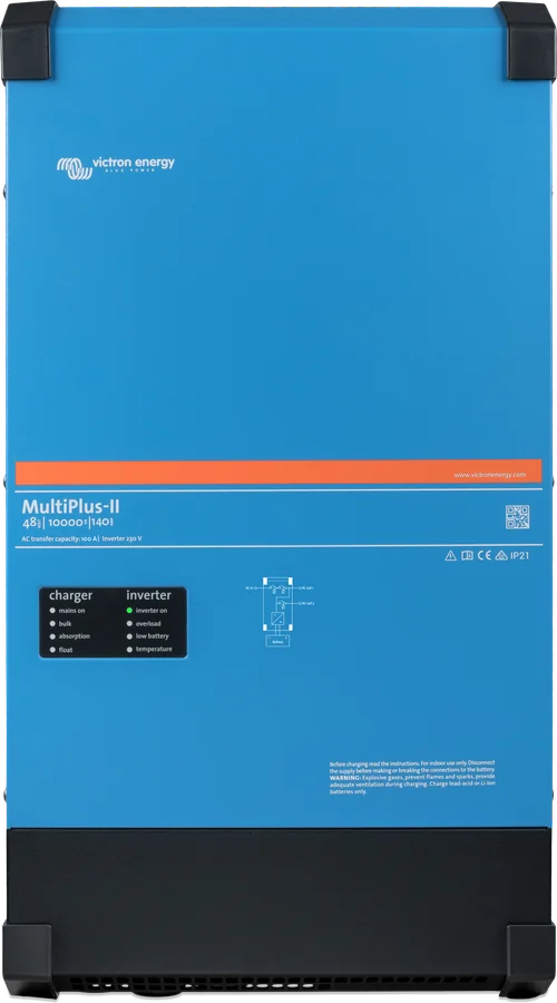
- MultiPlus-II → 230 VEnergy from the battery to the loads, in ESS working with the grid.
- Cerbo GXVE.Can from the controller, VE.Bus from the inverter — monitoring and VRM.


450 V DC is no joke
The manufacturer states that equipment with hazardous voltage should be installed under the supervision of an appropriately qualified installer, in accordance with local regulations.
The MPPT RS has no panel isolator. Between the panels and the controller there must be an isolator rated for direct current, for at least 450 V DC and the array current. Do not use switches intended for AC only.
The terminals may be live even after the device is switched off. Before working, disconnect the battery and panels, then wait at least 5 minutes.
The enclosure must be connected to protective earth (Class I device), and the conductor from the enclosure earth terminal to earth should be at least the same cross-section as the PV array cables. Earth the PV panel frame in accordance with local requirements, and the PV+ and PV− conductors must be insulated from earth. If the controller reports a panel insulation fault, do not touch any metal parts and call an installer.
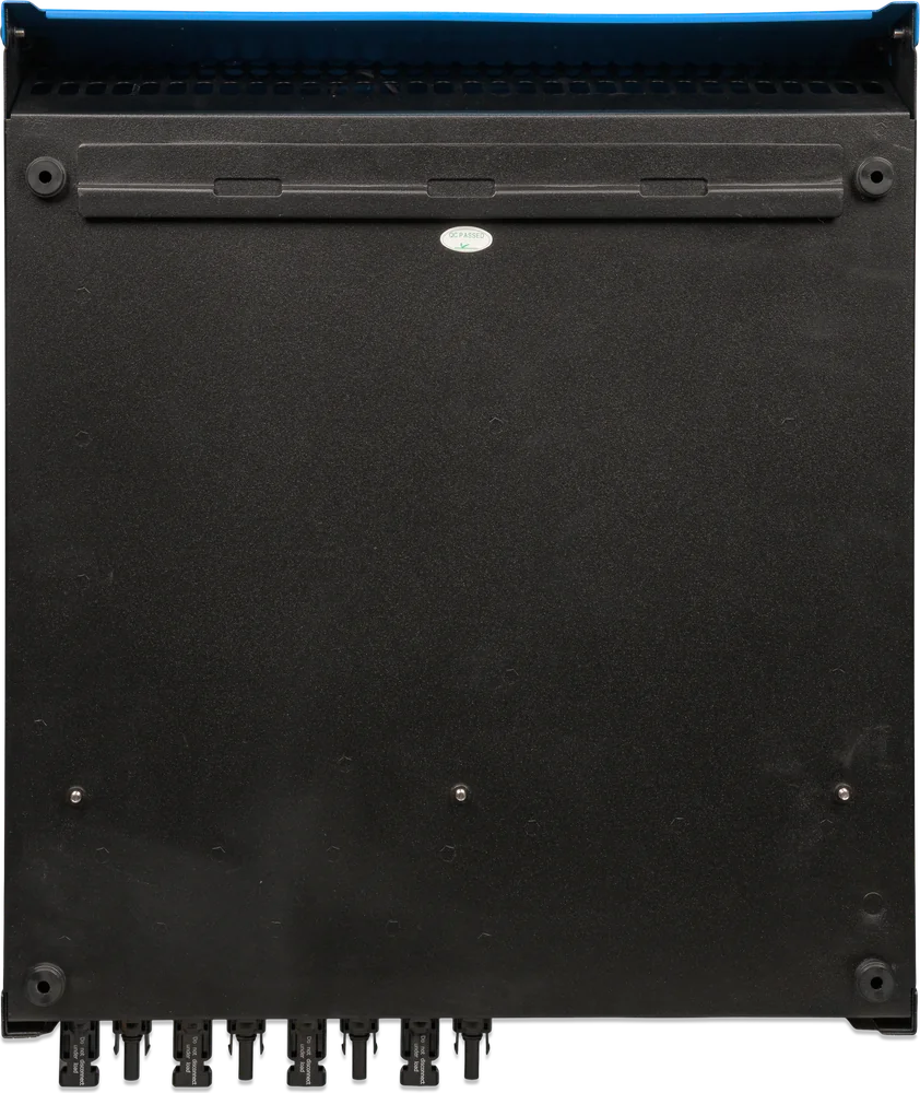
The controller uses Stäubli connectors. Connectors from other brands may fit poorly and overheat — the manufacturer recommends original connectors only.
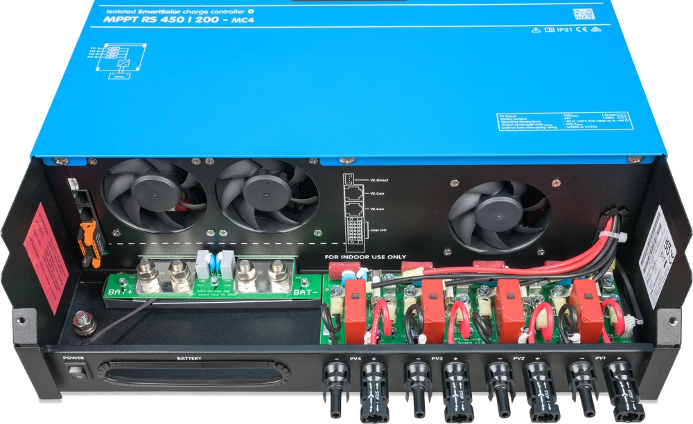
Location, cables, sequence
Mount the controller vertically on a non-combustible wall, in a dry indoor location, with no contact with water, rain or moisture, with a 30 cm clearance above and below the enclosure, and out of direct sunlight. The manual recommends an ambient temperature of −20 to 40 °C.
Do not mount directly above lead-acid batteries or where soot, dust or salt is present in the air — for example diesel generator exhaust can cause an internal short circuit. Do not mount it where flammable or corrosive gases or vapours could enter the installation; do not use the device where there is a risk of gas or dust explosion.
First the battery (check polarity), then the control and communication cables, and finally the panels — also after checking polarity. During installation, cover the PV modules from light, use insulated tools only, and never touch uninsulated wire ends.
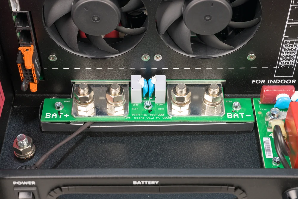
Minimum requirements according to the manual
| MPPT RS 450/100 | MPPT RS 450/200 | |
|---|---|---|
| Lead-acid battery capacity | 200 Ah | 400 Ah |
| Lithium battery capacity | 50 Ah | 100 Ah |
| Recommended DC fuse | 125–150 A | 250 A |
| Cable cross-section, 0–2 m | 35 mm² | 70 mm² |
| Cable cross-section, 2–5 m | 70 mm² | 2 × 70 mm² |
The cross-section applies to each positive and negative connection. The manufacturer recommends stranded copper cables (class 5) and determining battery capacity with the system designer. The minimum capacities in the table do not replace battery selection: check the battery manufacturer’s documentation to make sure it can accept the system’s total charging current.
Most common questions about the MPPT RS 450
Does the MPPT RS 450 work with a 12 V or 24 V battery?
No — this controller is for 48 V batteries only. Smaller SmartSolar controllers are used for 12 and 24 V installations, for example those described in the SmartSolar MPPT 75/10 – 100/20 datasheet.
Can I connect one string to two inputs to get more current?
No. The manufacturer requires each MPPT input to have its own panel array — the same string must not be connected to several trackers. The same applies to parallel operation of several controllers: each must have its own panels.
Does the MPPT RS work with Smart Battery Sense and the VE.Smart Network?
According to the MPPT RS datasheet, it currently does not work with VE.Smart Networking, so Smart Battery Sense is not needed: the controller has wired battery voltage and temperature measurement inputs (the temperature sensor is included). Several controllers synchronise via VE.Can, and GX provides coordination with the BMS.
What does the “Over-charge Protection” error mean?
The panel string voltage has exceeded 8 times the battery float voltage. When the controller enters the float stage, it limits current by raising the panel operating voltage — with too long a string it cannot do that. Solutions according to the manual: increase the float voltage or shorten the string by one or two panels.
Is the MPPT RS suitable for a grid-connected home?
Yes — the manufacturer intends it for both off-grid installations and grid-connected systems. In a home energy storage system (ESS) it works together with a MultiPlus-II inverter or Quattro-II and a GX device.
Devices it works with most often

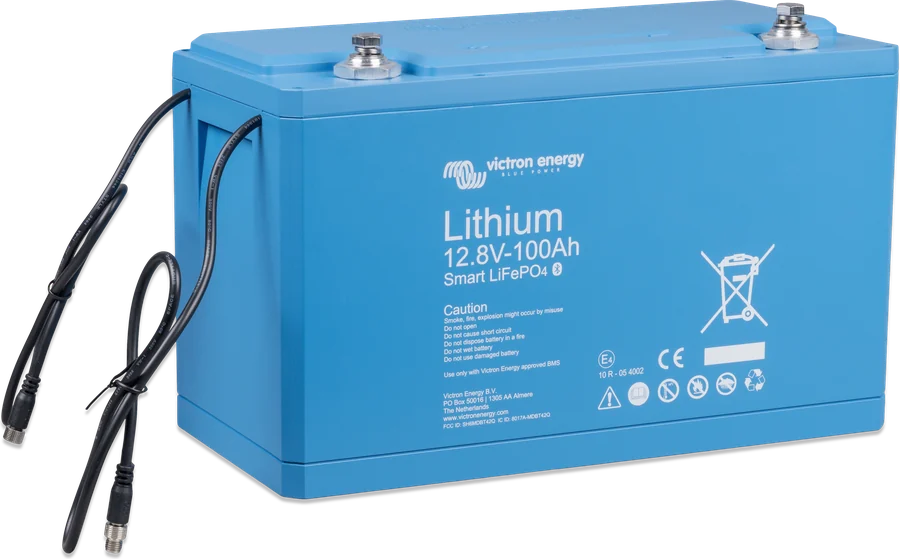
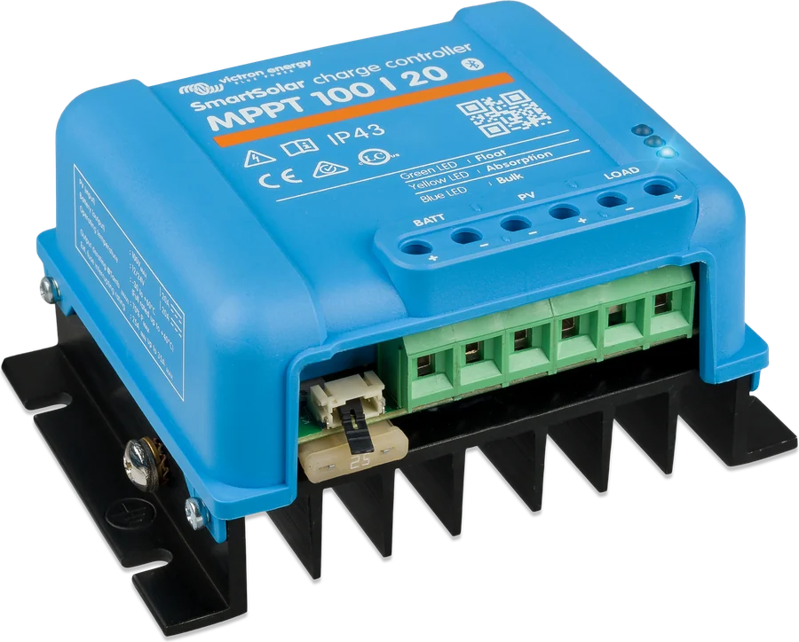
Manufacturer documentation
- SmartSolar MPPT RS 450|100 and 450|200 datasheetPDF · EN
- MPPT RS 450/100 and 450/200 manualPDF · EN
- Manufacturer product page (MPPT calculator, certificates)victronenergy.com
We prepared this description independently based on the manufacturer’s documentation. If there are any discrepancies, the current Victron Energy documentation is binding. You can report an error here.
Content checked against Victron Energy documentation (datasheets and manuals) — as of 19 September 2026. Report a content error · Revision log