
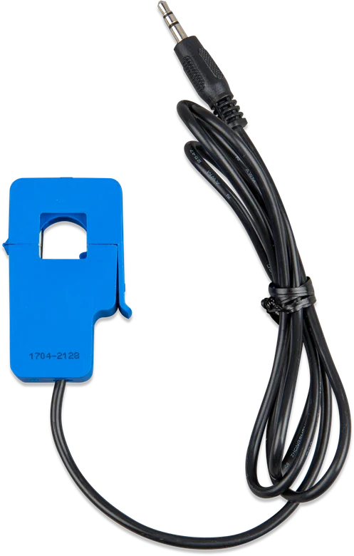
100 A current transformer with cable and plug for MultiPlus-II
Current transformer for MultiPlus-II
A split-core transformer fitted around the phase conductor. It allows MultiPlus-II to measure current flowing to and from the mains without passing it through the inverter — so PowerControl, PowerAssist and self-consumption optimisation work where a full energy meter is not needed.
- 100 A or 400 A
- 50 mV ratio
- 1, 5 or 20 m cable
- single phase
- without cutting into the installation
MultiPlus-II sees current that does not flow through it
MultiPlus-II measures current with its own internal transformer — but only the current passing through its AC input. In a parallel arrangement with the mains, some loads are connected directly to the supply, so the inverter does not know how much energy the whole house is using.
An external transformer is fitted around the phase conductor before the circuits are split. MultiPlus-II then knows how much current flows to and from the mains and can use this to limit import (PowerControl), add power from the battery (PowerAssist) and increase self-consumption.
- it is fitted around the existing conductor — no need to cut into the installation,
- cheaper and quicker to install than a DIN-rail energy meter,
- useful where there is no room left in the consumer unit for a meter.
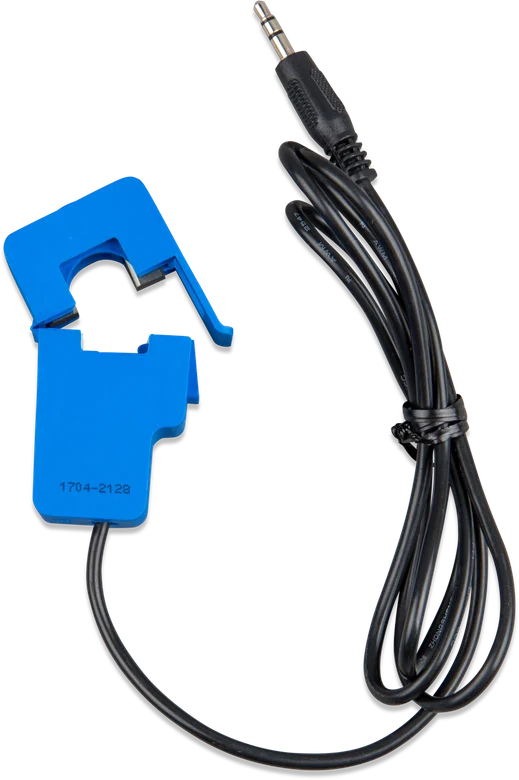

What external current measurement gives you
Current to and from the mains
Based on the measurement, MultiPlus-II knows which direction current is flowing through the supply and how much — even when some loads are outside its AC output.
PowerControl and PowerAssist
External measurement extends both functions: in 3 kVA models to 50 A, and in 5 kVA models to 100 A. The inverter adds battery power only when the supply is genuinely close to its limit.
Higher self-consumption
In a parallel arrangement with the mains, the measurement lets you use your own energy instead of exporting it to the grid, and if needed completely prevent export.
Installation without modifications
The core opens and clips around the existing phase conductor. There is no need to cut the installation or route conductors through the inverter.
System with an external transfer switch
In a three-phase system with an external transfer switch, the transformer is mandatory — one per phase, connected to the master unit of that phase.
Two connection types
Newer MultiPlus-II and MultiPlus 20 kW models have a two-wire terminal block; older units have a jack socket. There is a separate transformer version for each.
Three cable lengths
1 m, 5 m and 20 m — choose according to the distance between the distribution board and the inverter. The cable must not be shortened or extended.
Two ranges
The 100 A version is for typical installations and the 400 A version is only for systems with an external transfer switch. Both provide a 50 mV output signal.
Which transformer for which inverter
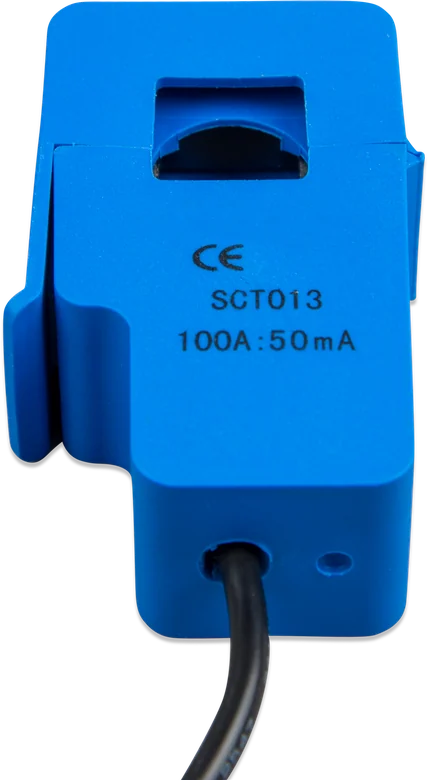
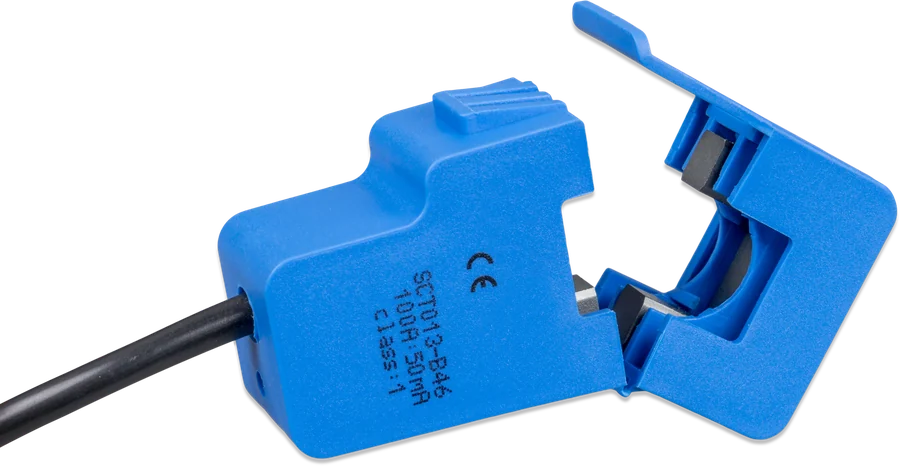
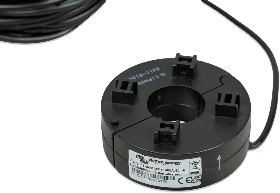
| Model | Cable length | Conclusion | What it is for |
|---|---|---|---|
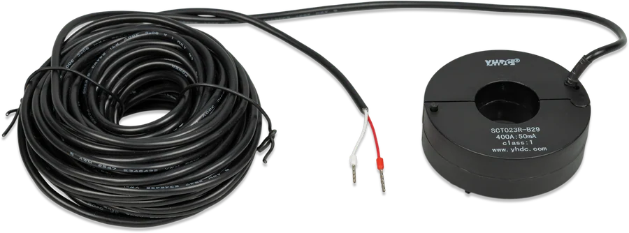
| 100 A : 50 mA | 1 m, 5 m or 20 m | wire ends | newer MultiPlus-II models and the MultiPlus 20 kW |
| 100 A : 50 mA | 1 m, 5 m or 20 m | jack plug | older MultiPlus-II models with a socket |
| 400 A : 50 mA | 10 m | wire ends | MultiPlus-II in a system with an external transfer switch (firmware s99) |
Before ordering, check which connection your inverter has: newer models have a two-wire terminal block labelled EXT and COM, older ones have a jack socket. The 400 A version has only one use: a system with an external transfer switch, where it replaces the internal transfer switches of the individual units.
How to connect the current transformer
The transformer clips onto the shore power phase conductor, and its wires go to the external current measurement terminals in the MultiPlus-II. The arrow on the casing must point towards the inverter. Hover over or touch the diagram element. Illustrative diagram.
- Mounting locationShore power phase conductor, before the circuits are split.
- DirectionThe arrow on the transformer points towards the MultiPlus-II.
- Newer modelsRemove the link, red wire to EXT, white to COM — the transformer is polarity-sensitive.
- Older modelsThe jack plug is inserted into the external current measurement socket.
- CableDo not shorten or extend it — it is calibrated together with the transformer.
Four things you need to get right
The arrow on the transformer casing must point towards the MultiPlus-II. If fitted the wrong way round, the sign of the measurement is reversed, so the inverter “sees” energy flowing in the wrong direction.
The cable is calibrated together with the transformer — shortening or extending it changes the measurement result. Choose the length when you buy it: 1, 5 or 20 m.
In newer MultiPlus-II models, first remove the link from the external measurement terminals. The transformer is polarity-sensitive: red wire to terminal EXT, white to COM.
- One phase per transformer. In a three-phase system with an external transfer switch, you need a separate transformer for each phase, connected to the master unit for that phase.
- Work in the distribution board must be carried out by a qualified person, with the power isolated. The transformer is fitted around an insulated conductor — not a bare core.
- The 400 A version may be used only in a system with an external transfer switch — it has no use in a standard installation.
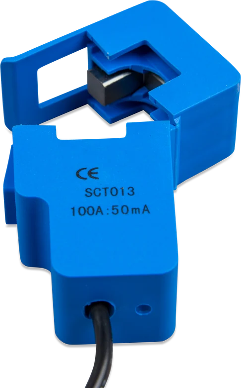
Transformer or energy meter
Current transformer
The simplest solution: clip it onto the conductor and connect it directly to the inverter. It measures current only and only on one phase, but it does not require space in the distribution board or separate communication.
100 A · one phaseEnergy Meter VM-3P75CT
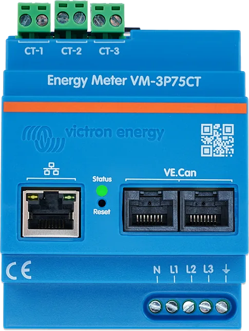
An energy meter measures current and voltage, supports one-phase and three-phase systems, counts energy and sends data to the GX device via VE.Can or Ethernet. VM-3P75CT meter datasheet.
power, energy, 3 phasesMultiPlus-II GX
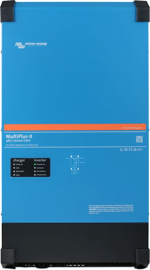
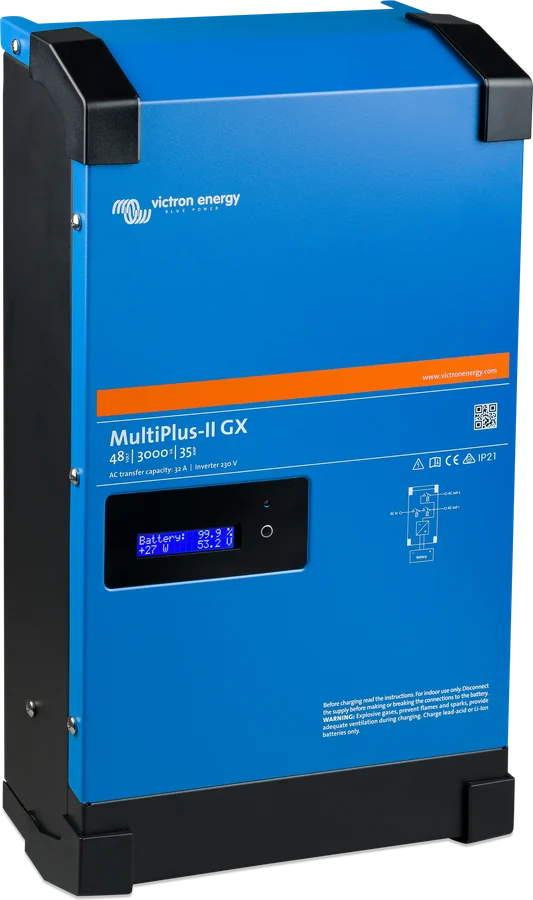
If you are just building the system, an inverter with a built-in GX device makes it easier to expand with an energy meter and to monitor it in VRM. MultiPlus-II GX datasheet.
inverter + GXWhat the transformer cannot do
- One phase only. The manufacturer provides for single-phase measurement; in a three-phase system with an external transfer switch, you need a separate transformer for each phase.
- It measures current, not voltage. It is not a substitute for an energy meter: it does not provide reactive power, power factor or energy used in kilowatt-hours.
- Lower accuracy than a dedicated energy meter, especially at low currents.
- Fixed cable length — shortening or extending it is not permitted, because it changes the calibration.
Symptom and what to do about it
The inverter shows flow in the wrong direction
The transformer is fitted the wrong way round, or the wires are swapped. The arrow on the casing must point towards the MultiPlus-II, the red wire goes to terminal EXT, the white to COM.
No measurement despite being connected
In newer MultiPlus-II models, you must first remove the link from the external current measurement terminals — while it is still there, the inverter will not read the signal from the transformer.
The reading differs from the utility meter
The transformer is less accurate than an energy meter, especially at low currents. Also check that the cable has not been shortened and that the core closes fully.
PowerAssist responds too late or too early
Check that the transformer is on the correct conductor — it must be the shore power phase conductor before the circuits are split, not an individual load circuit.
The three-phase system does not work correctly
In a configuration with an external transfer switch, each phase needs its own transformer, connected to the master unit for that phase.
The plug does not fit the inverter
Newer models have a terminal block and require the version with wire ends; older ones have a jack socket. These are two different versions of the same transformer.
Frequently asked questions about the current transformer
Why does the MultiPlus-II need an external transformer?
In a parallel system with the grid, the inverter’s internal transformer cannot measure current flowing to and from the grid, because some loads are outside its AC output. The external transformer provides that measurement and allows PowerControl, PowerAssist and self-consumption optimisation to work.
How do you orient the transformer?
The arrow on the casing must point towards the MultiPlus-II. The transformer is also polarity-sensitive: red wire to terminal EXT, white to COM.
Can I shorten a cable that is too long?
No. The cable is calibrated together with the transformer, so shortening or extending it is not an option. Choose the length when you buy it: 1 m, 5 m or 20 m.
Which version should I buy for my inverter?
For newer MultiPlus-II models and the MultiPlus 20 kW — the version with wire ends, connected to a terminal block. For older MultiPlus-II units — the version with a jack plug.
What is the 400 A version for?
Only for systems in which an external transfer switch replaces the internal transfer switches of the individual MultiPlus-II units. It has no use in a standard installation.
Can the transformer replace an energy meter?
Only where knowing the current is enough. It does not measure voltage, is less accurate than a meter (especially at low currents) and supports one phase. A full picture is provided by Energy Meter VM-3P75CT.
Do I need to modify the installation?
No. The core opens and clips around the existing phase conductor, so there is no need to cut the circuit or route wires through the inverter. The work in the distribution board itself should be done by a qualified person.
What is the output signal?
50 mV at rated current — the same for the 100 A and 400 A versions. The signal goes directly to the inverter’s external current measurement input.

Content compared with Victron Energy documentation (datasheets and manuals) — current as of 20 September 2026. Report a content error · Correction log