
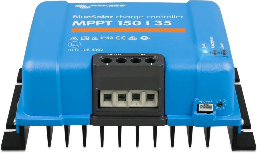
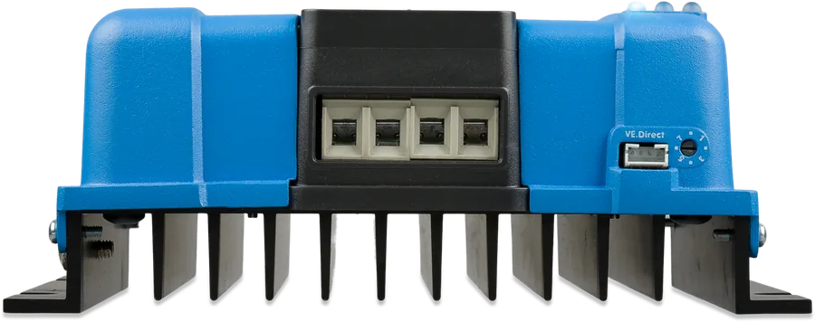
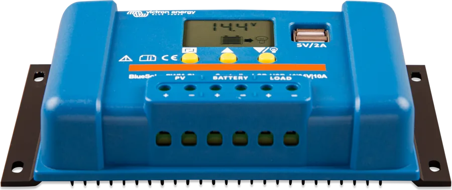
BlueSolar MPPT 150/35 from the front — blue housing with heatsink, terminal cover and VE.Direct port
BlueSolar MPPT 150/35–250/100
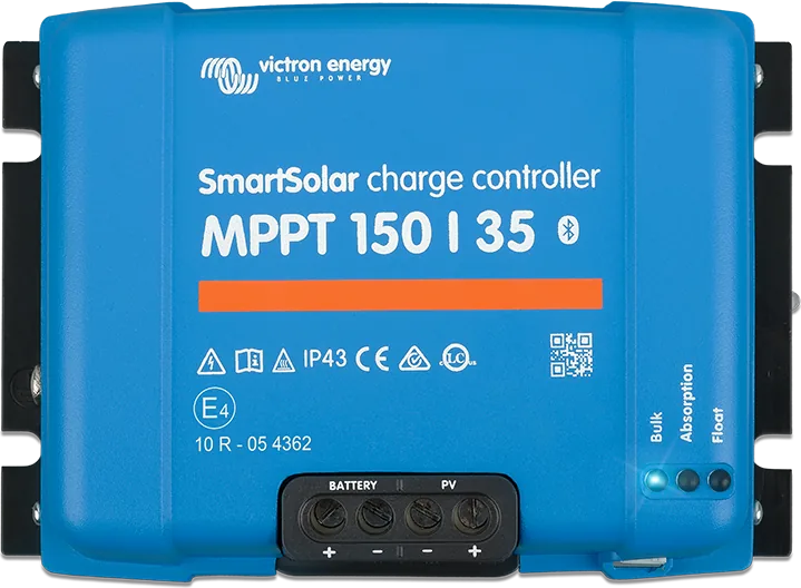
Victron MPPT controllers without built-in Bluetooth — electrically equivalent to the SmartSolar 150 and 250 V controllers. They charge 12, 24, 36 or 48 V batteries at 35–100 A from panels with up to 150 V or 250 V. The charging algorithm is selected with a rotary switch, and they connect to VictronConnect through a Bluetooth dongle, USB cable or via GX.
- 12/24/36/48 V
- 35–100 A
- PV up to 150 V or 250 V
- VE.Direct
- VE.Can (Tr VE.Can models)
Controller for an installation where you do not need a phone
BlueSolar MPPT charges the battery from solar panels: it matches the panel operating point to maximum power (MPPT), so it collects up to 30% more energy than a PWM controller and up to 10% more than slower MPPT controllers. With partial shading, when there are two maximum power points in the characteristic, it looks for the correct one.
The lack of Bluetooth does not limit the controller’s operation — it is suitable where you configure it once (with the switch or through a dongle connected for setup), and the data go by cable to the GX device and the VRM portal.
- fanless; full current up to 40 °C ambient, above that — power reduction,
- protection against reverse polarity and PV short circuit, PV reverse current and overheating,
- three-stage charging (bulk, absorption, float) with adaptive absorption time and temperature compensation,
- automatically detects 12, 24 or 48 V; 36 V is set manually.
BlueSolar or SmartSolar
BlueSolar MPPT
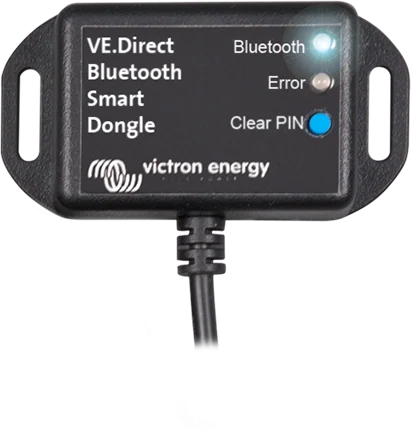
No Bluetooth. View and settings via a VE.Direct Bluetooth Smart dongle, VE.Direct–USB interface, GX or MPPT Control display. VE.Smart networking (for example Smart Battery Sense) — dongle only.
dongle or cable for the appSmartSolar MPPT
The same current and voltage ranges, built-in Bluetooth — app and VE.Smart networking without extras.
SmartSolar 150 and 250 VUp to 100 V from panels
The small BlueSolar units (75/10–100/50) are not in Victron’s product range — in this range there are SmartSolar controllers.
SmartSolar 75/10–100/20Seven models in three housings
| Model | Current | Nominal PV power (12 / 24 / 36 / 48 V) | Max PV Isc | Battery fuse | Dimensions, weight |
|---|---|---|---|---|---|
| 150/35 | 35 A | 500 / 1000 / 1500 / 2000 W | 40 A | 40–45 A | 130 × 186 × 70 mm, 1.25 kg |
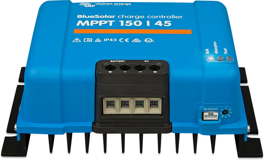
| 150/45 | 45 A | 650 / 1300 / 1950 / 2600 W | 50 A | 50–63 A | 130 × 186 × 70 mm, 1.25 kg |
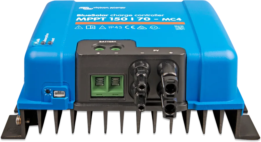
| 150/60 Tr / MC4 | 60 A | 860 / 1720 / — / 3440 W | 50 A | 70–80 A | Tr 185 × 250 × 95, MC4 215 × 250 × 95 mm; 3 kg |
| 150/70 Tr / MC4 | 70 A | 1000 / 2000 / — / 4000 W | 50 A | 80–100 A | Tr 185 × 250 × 95, MC4 215 × 250 × 95 mm; 3 kg |
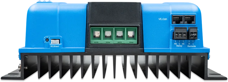
| 250/70-Tr VE.Can | 70 A | 1000 / 2000 / 3000 / 4000 W | 35 A | 80–100 A | 185 × 250 × 95 mm, 3 kg |
| 150/100-Tr VE.Can | 100 A | 1450 / 2900 / 4350 / 5800 W | 70 A | 120–140 A | 216 × 295 × 103 mm, 4.5 kg |
| 250/100-Tr VE.Can | 100 A | 1450 / 2900 / 4350 / 5800 W | 70 A | 120–140 A | 216 × 295 × 103 mm, 4.5 kg |
Common: max. PV voltage 150 V (in the 150 model name) or 250 V (in the 250 model name) in the coldest conditions, 145 V or 245 V as the start and operating maximum; start when PV exceeds battery voltage by 5 V, then +1 V is enough. Max. efficiency 98% (150/35–150/70, 150/100) or 99% (250/70, 250/100). Self-consumption 10–20 mA (150/35 and 150/45: 20 mA at 12 V), in VE.Can models below 35 mA at 12 V. Factory absorption 14.4 / 28.8 / 43.2 / 57.6 V, float 13.8 / 27.6 / 41.4 / 55.2 V, compensation −16 / −32 / −64 mV/°C. IP43 (electronics), IP22 (terminal area). Higher panel power than nominal is allowed — the controller will limit input power; higher PV short-circuit current may damage it. Battery fuse — minimum and maximum value according to the manual.
How to connect a BlueSolar MPPT
First battery (the controller detects the voltage within 10 s), then the panels, and finally VE.Direct and the other connections. Basic diagram.
- BatteryWith a fuse according to the manual; connect the first one and wait 10 s.
- PV panelsVia a disconnector; Voc ≤ 150 V or 250 V in frost.
- VE.DirectTo GX, Bluetooth dongle, USB interface or MPPT Control display.
- SettingsRotary switch or VictronConnect.
Installation rules
The PV, battery and control circuits must be treated as hazardous and protected against accidental touch — enclosure or MPPT WireBox cover. Check polarity before connecting.
- Order: first battery (automatic voltage detection, about 10 s), then PV, and finally the other connections. You may connect PV first only if the system voltage has already been set manually.
- Location: vertically on a non-combustible surface, terminals down, 10 cm clear space above and below the controller, up to 3 m from the battery, never above the battery.
- Terminals: stranded copper wire; torque 1.6 Nm (150/35, 150/45) or 2.4 Nm (150/60 and larger).
- Panels: when selecting the number of panels in series, take Voc and the temperature coefficient into account. Open-circuit panel voltage (Voc) increases when the temperature falls below 25 °C — by the percentage per degree stated by the Voc temperature coefficient in the panel datasheet. With Victron BlueSolar panels (−0.35%/°C), at −20 °C this is about 16% more than in the catalogue. Do not use panels with optimisers.
- Earthing: the controller works with a grounded battery negative or positive — one earth connection only, preferably at the battery. PV poles are not earthed; earth the panel frames.
- Example for 150 V: 24 V battery — at least 72 cells in series (2 × 12 V panels), ideally 144, maximum 216; 48 V battery — 144–216 cells. You can calculate it exactly in the MPPT calculator.
Eight charging algorithms without an app
Use the switch (small flat screwdriver) to select one of eight pre-programmed algorithms. Changing the switch overwrites the settings from the app and display — and vice versa. Values are for 12 V; for 24 V multiply by 2, for 48 V by 4.
| Pos. | Battery type | Absorption | Float | Equalisation (current) | Compensation |
|---|---|---|---|---|---|
| 0 | long life gel (OPzV), Exide A600, MK | 14.1 V | 13.8 V | 15.9 V (8%) | −16 mV/°C |
| 1 | Victron deep discharge gel and AGM, Exide A200, OPzS | 14.3 V | 13.8 V | 16.1 V (8%) | −16 mV/°C |
| 2 (factory) | Victron deep discharge gel and AGM, Exide A200, OPzS | 14.4 V | 13.8 V | 16.2 V (8%) | −16 mV/°C |
| 3 | AGM spiral, OPzS, Rolls AGM | 14.7 V | 13.8 V | 16.5 V (8%) | −16 mV/°C |
| 4 | traction PzS or OPzS | 14.9 V | 13.8 V | 16.7 V (25%) | −16 mV/°C |
| 5 | traction PzS or OPzS | 15.1 V | 13.8 V | 16.9 V (25%) | −16 mV/°C |
| 6 | traction PzS or OPzS | 15.3 V | 13.8 V | 17.1 V (25%) | −16 mV/°C |
| 7 | lithium iron phosphate (LiFePO4) | 14.2 V | 13.5 V | — | 0 |
Equalisation charging is factory disabled — you enable it in the app. After turning the switch, the LEDs show the selected position in binary code for 4 s. In the 150/35 and 150/45, absorption ends when current falls below 2 A; its time increases after deep discharge. Table according to the BlueSolar 150/35 and 150/45 manual.
VE.Direct, VE.Can, relay
VE.Direct port
All models. VE.Direct cable to GX or GlobalLink 520, VE.Direct Bluetooth Smart dongle, VE.Direct–USB interface, MPPT Control display, remote on/off cable or TX cable (e.g. street lighting, virtual load output).
VE.Can (Tr VE.Can models)
Up to 25 controllers daisy-chained and synchronised, each shown separately in GX and VRM. Optional plug-in SmartSolar display instead of the front rubber plug.
Relay (Tr VE.Can models)
Programmable, DPST: 240 V AC / 4 A, DC 4 A up to 35 V and 1 A up to 60 V — e.g. alarm or virtual load output. Also a 2-pin remote on/off connector, e.g. for VE.Bus BMS.
Sensors via Bluetooth
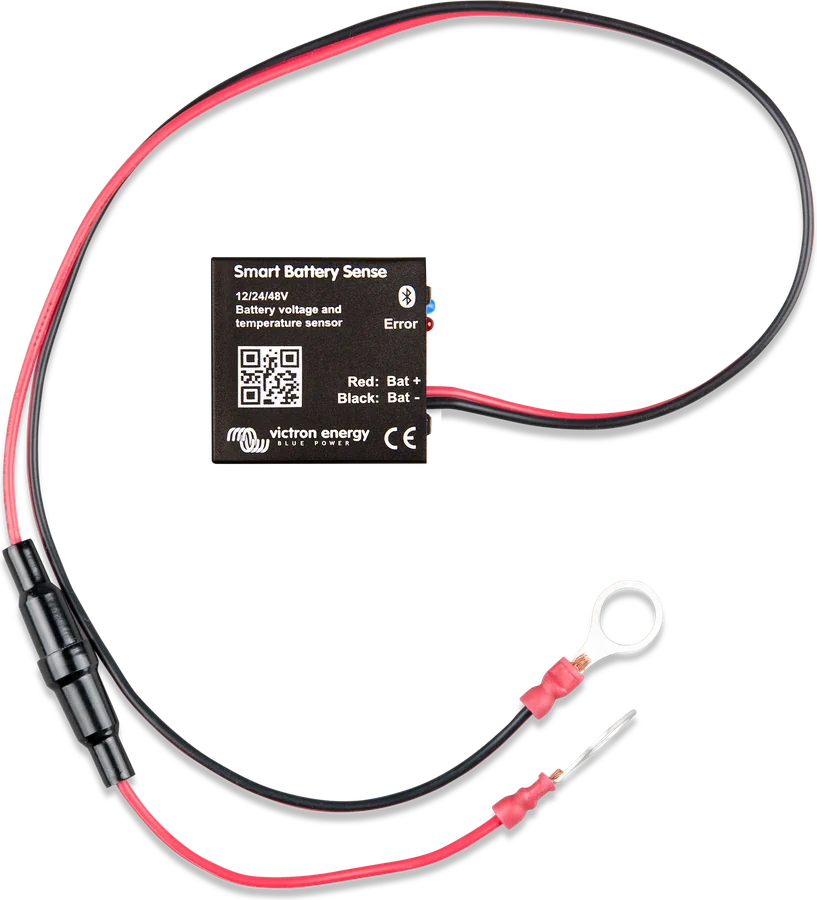
With a VE.Direct Bluetooth Smart dongle, the controller joins the VE.Smart network: Smart Battery Sense, BMV-712 or SmartShunt provide battery voltage and temperature (BMV-712 and SmartShunt also current).
Parallel operation
150/60 and 150/70 — in parallel without synchronisation; VE.Can models — synchronised via VE.Can. Each controller has its own panel array.
History and updates
In VictronConnect: 30 days of history and errors, all settings and firmware updates. The app also allows a full custom charging algorithm.
The datasheet lists only the VE.Direct port for these models (remote on/off via VE.Direct cable), and mentions the relay only for VE.Can models. However, the 150/60 and 150/70 manual shows relay and remote on/off terminals in the connection overview. Check this on your own unit.
Most common questions about BlueSolar MPPT
How does BlueSolar differ from SmartSolar?
Mainly by built-in Bluetooth, which BlueSolar does not have. The current and voltage ranges are the same. With the VE.Direct Bluetooth Smart dongle, BlueSolar connects to the app and the VE.Smart network like SmartSolar — but the dongle takes up the only VE.Direct port.
Can I connect more panels than the nominal power says?
Yes — the controller will limit input power. However, you must not exceed the maximum PV voltage (150 V or 250 V in the coldest conditions) or the maximum PV short-circuit current — this may damage the controller.
How do I set the controller for a LiFePO4 battery without the app?
Rotary switch position 7: absorption 14.2 V, float 13.5 V (for 12 V), with no temperature compensation. You can set other values, for example those recommended by the battery manufacturer, only in the app or on the display.
How do I connect the controller to a Cerbo GX?
With a VE.Direct cable (or via a VE.Direct–USB interface). VE.Can models can also be connected via VE.Can — including several controllers daisy-chained.
The controller does not charge in the morning — why?
PV voltage must exceed battery voltage by 5 V for the controller to start. When there is too little power, the bulk LED briefly flashes every 3 seconds. We describe full diagnostics in the guide MPPT does not charge, and the error codes are on the charger and MPPT error codes page.
Will the 150/60-MC4 accept one large string of panels?
The maximum current per MC4 connector is 30 A. Two pairs of connectors are connected in parallel to one MPPT tracker — with more strings, MC4 branch connectors are required.
Does the controller have a load output?
There is no physical one. A virtual load output is created with a VE.Direct TX cable (or a relay in VE.Can models) and controlled by battery voltage or the BatteryLife algorithm.
Manufacturer documentation
- BlueSolar MPPT 150/35 and 150/45 datasheetvictronenergy.com · PDF · EN
- BlueSolar MPPT 150/60 and 150/70 datasheetvictronenergy.com · PDF · EN
- BlueSolar MPPT 250/70, 150/100 and 250/100 VE.Can datasheetvictronenergy.com · PDF · EN
- BlueSolar MPPT 150/35 and 150/45 manual (rev 12, 06/2026)victronenergy.com · EN
- BlueSolar MPPT 150/60 and 150/70 manual (rev 12, 06/2026)victronenergy.com · EN
- BlueSolar MPPT 150/100 to 250/100 VE.Can manual (rev 12, 06/2026)victronenergy.com · EN
Content checked against Victron Energy documentation (datasheets and manuals) — status as of 23 September 2026. Report an error in the content · Correction log