
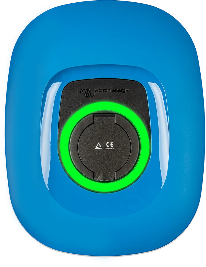
EV Charging Station NS from the front — blue front, Type 2 socket under the flap and a green-lit light ring
EV Charging Station NS
AC charging station for an electric car: up to 22 kW on three phases or 7.3 kW on one, current adjustable from 6–32 A. It works with a Victron system via a GX device, so in automatic mode it charges the car with surplus energy from the panels instead of exporting it to the grid at a lower price. “NS” means the screenless version — operation from a phone, browser, GX and VRM.
- 22 kW / 7.3 kW
- 6–32 A per phase
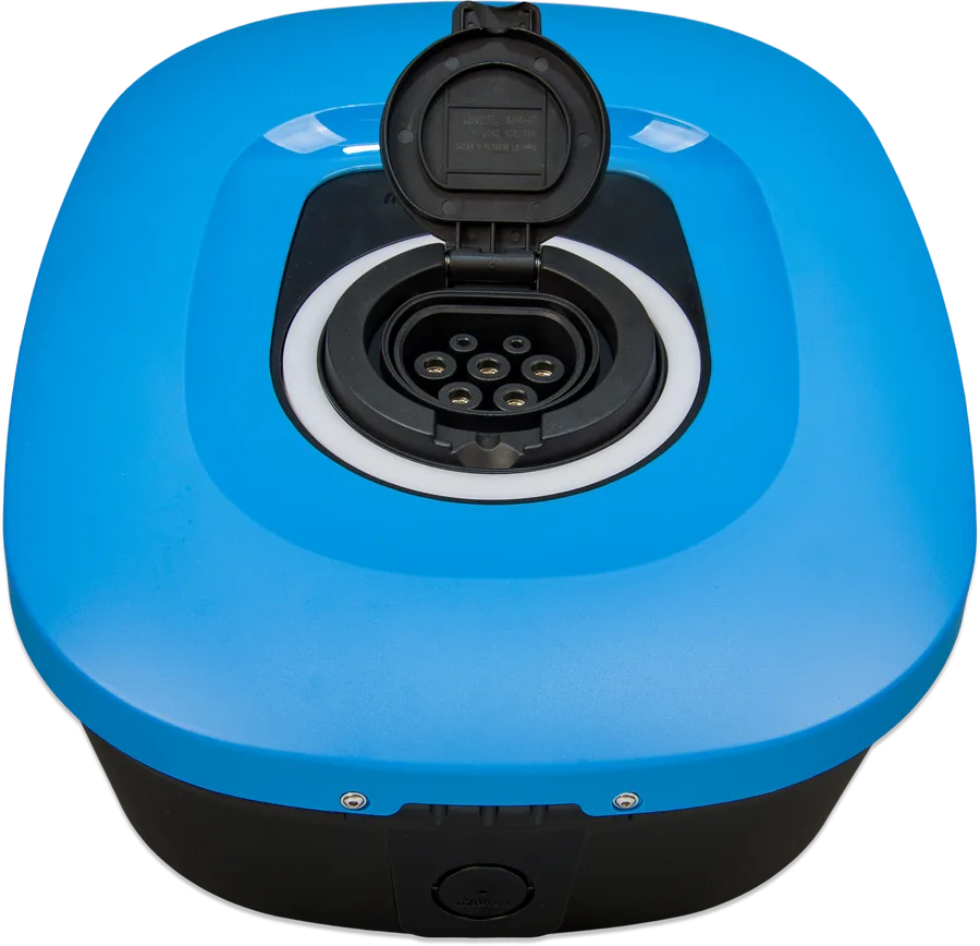
- Type 2 socket
- Wi-Fi 2.4 GHz and Bluetooth
- IP44, −25…+50 °C
The car as a second storage for energy from the panels
In a home with solar PV and an energy storage system, the battery fills up quickly in summer and energy starts being exported to the grid. EV Charging Station takes over this surplus: when the house battery has reached the set state of charge and the panels are producing more than the loads are using, the station charges the car — and automatically matches the current to whatever surplus is left at the time.
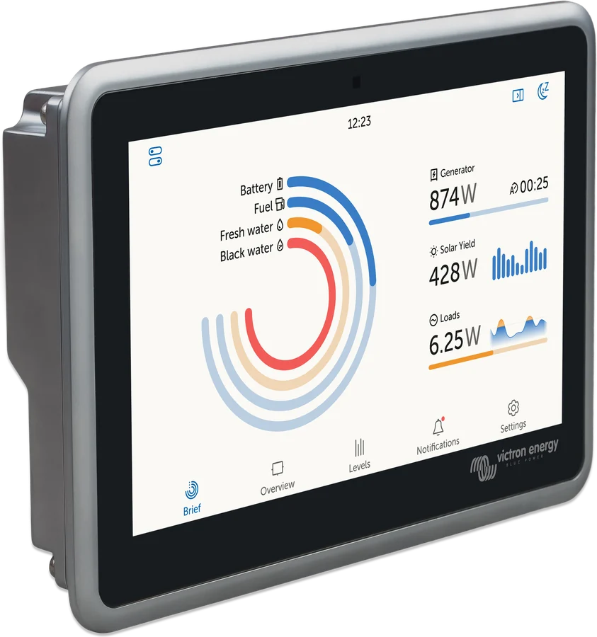
Information about PV production and home consumption is taken by the station from the GX device (Cerbo GX, Ekrano GX), which connects via Wi-Fi. Without GX, it works like a normal wall charger: it charges manually or according to a schedule, for example on an off-peak tariff at night.
- three phases — up to 22 kW (32 A per phase), one phase — up to 7.3 kW,
- Type 2 socket (IEC 62196) — cable to the car not included,
- IP44 enclosure for wall or post mounting, indoors and outdoors,
- operated from VictronConnect (Bluetooth), browser page, GX device and the VRM portal.
Automatic, manual, schedule
Automatic (Auto)
The station charges only when the panels are producing more than the house is using, and continuously adjusts the current. It requires a GX device and communication with it enabled. It also works in an off-grid installation.
from 6 A × 230 V ≈ 1.4 kW surplusManual
You set the current from 6–32 A and start or stop charging yourself — regardless of panel production. From the app, browser, GX screen, Remote Console or buttons in VRM.
GX not requiredScheduled
Charging at selected times and days of the week, with a separate current for each schedule — for example at night, when grid energy is cheaper. Correct date and time required.
GX not requiredWhen charging starts in automatic mode
- The car is connectedThe station is in Auto mode.
- The house battery has enough energyThe state of charge is above the “Start charging at backup battery SoC” threshold.
- There is PV surplusPV production minus AC loads (excluding the car) gives at least the power at the minimum charging current. At 6 A, that is 230 V × 6 A = 1380 W; a higher minimum current needs a larger surplus.
- Or you have allowed grid top-upThe “Allow low excess solar power for auto mode” option makes up the missing power from the grid. Example from the manual: with 800 W of surplus and 6 A, the station will draw 580 W from the grid to reach 1380 W.
Some cars need a higher minimum current — the manual gives the Renault Zoe as an example: 10 A. In that case, set “Minimum charging current” accordingly.
What EV Charging Station can do
Charging from PV surplus
In Auto mode, charging current follows the PV surplus. The default algorithm is based on the house battery, so automatic mode also works off-grid.
Inverter overload protection
When the inverter reports overload, the station reduces current to the minimum and waits about 5 s; if the overload continues, it stops charging. If overloads repeat, it reduces the current by 10%. It reacts the same way to exceeding the grid current limit.
Integration with GX and VRM
Status, power on each phase and mode changes on the GX screen and in Remote Console. In VRM: reports, remote firmware updates, buttons in the dashboard, VRM app widgets and access to the station page through “Control Panel”.
Schedules
Any number of schedules: start and end time, current, repeat daily, on weekdays, at weekends or on selected days.
Session statistics
Session time and energy, grid energy cost and savings from panel energy (based on the set price per kWh — factory default 0.13 €), energy from the installation.
Light ring
55 light effects to choose from. For each state you can set the effect, colour, time and brightness from 0–100% — brightness 0 turns the ring off, for example at night.
Safety sensors
Detects welded relay contacts, missing protective conductor, missing earthing and CP line short circuit. IEC 61851-1 and IEC 61851-22.
Several stations in one system
Several stations can work in one installation — available power is then divided between them. Self-consumption of one station is 15 mA at 230 V.
NS or screen version
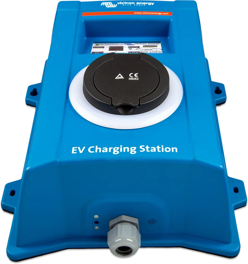
EV Charging Station NS
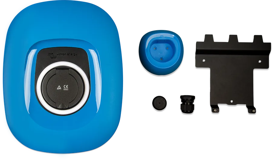
Screenless, lower enclosure with interchangeable front panel. Operated from VictronConnect, browser, GX and VRM (also remotely via VictronConnect-Remote).
EVC200300200EV Charging Station
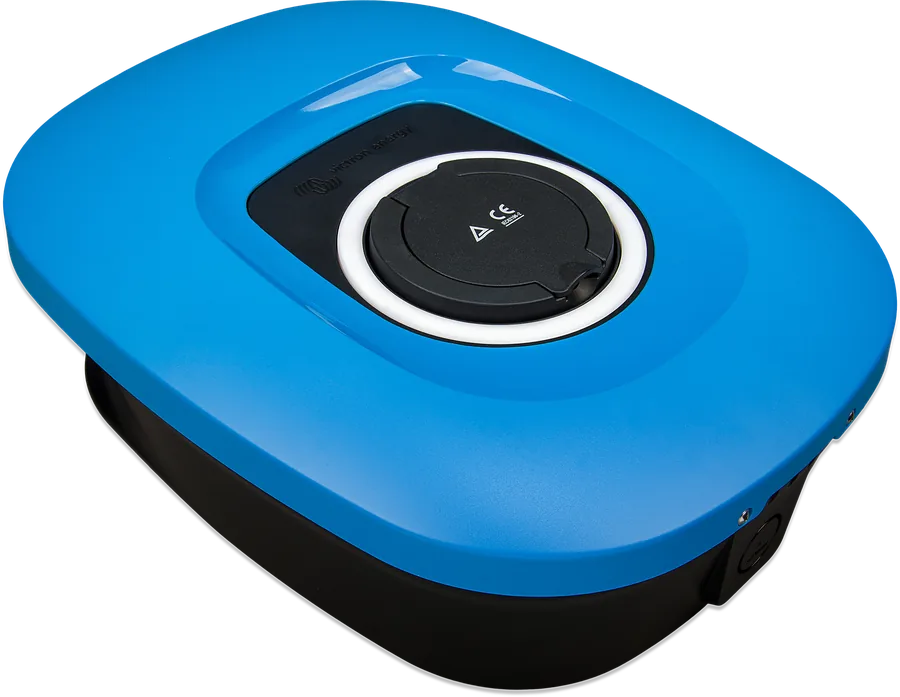
The same electrical specifications and the same modes, plus a 4.3″ touchscreen on the station. You can start the first setup from the QR code on the screen.
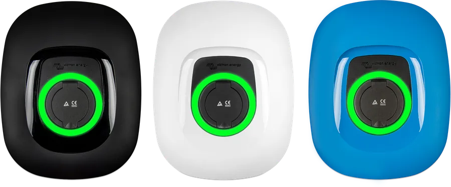
EVC300400300Black or white front
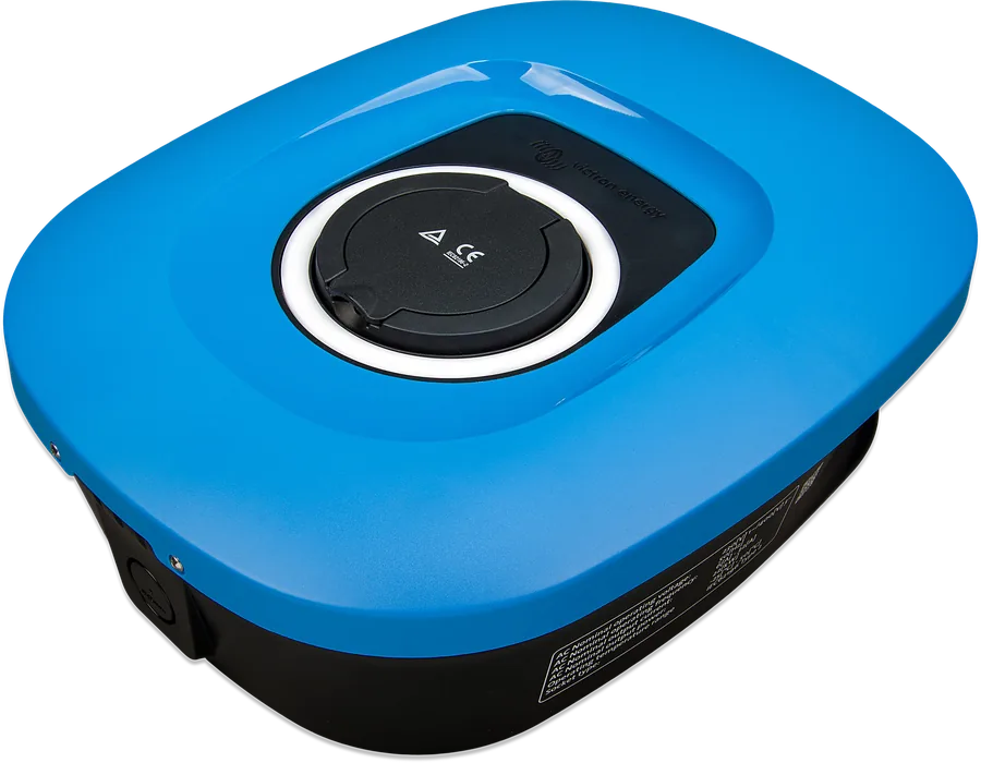
Replacement cover for the NS version: black (RAL 9017) or white (RAL 9016). The station comes with a blue front (RAL 5012) as standard.
EVC200300310 / EVC200300410| EV Charging Station NS | EV Charging Station (with screen) | |
|---|---|---|
| Part number | EVC200300200 | EVC300400300 |
| Operation on the station | none — only light ring | 4.3″ LCD touchscreen and light ring |
| Dimensions (H × W × D) | 372 × 292 × 122 mm | 377 × 307 × 148 mm |
| Colour | blue front included; black and white separate | blue (RAL 5012) |
| Installation | mounting plate, 3 holes, cable from bottom or rear | rear plate as template, 4 holes, cable through gland |
| Software (update file) | “C026” in the file name | “C025” in the file name |
Common: 170–265 V AC, 50 Hz; 32 A per phase, 22 kW (3 phases) or 7.3 kW (1 phase); current 6–32 A; IEC 62196 Type 2 socket; Wi-Fi 802.11 b/g/n, 2.4 GHz only; Bluetooth; 6–10 mm² terminals; IP44; fanless; −25…+50 °C (storage −40…+80 °C); humidity up to 95% non-condensing; 3 kg; IEC 61851-1 and IEC 61851-22. Both versions require an external switch and an external residual current device.
How to connect the EV Charging Station
Variant with the station on the AC input of the inverter/charger (grid side). You can also connect the station to the inverter AC output — then choose “Inverter AC out” in the settings. Illustrative diagram; installation must be carried out only by a qualified electrician.
- ProtectionsSwitch or fuse ≤ 40 A and external RCD — B type recommended, 40 A at 22 kW.
- Cable6 mm² recommended; terminals accept 6–10 mm². Single-phase: L1, N and PE.
- Position in the installationOn the inverter AC input (“Inverter AC in”) or on its AC output (“Inverter AC out”).
- Connection to GXWi-Fi 2.4 GHz on the same subnet, MQTT pairing.
- CarDedicated Type 2 cable; the station sets current 6–32 A.
The manual shows all variants in one diagram: PV inverter on the AC input and AC output, MPPT on the DC side, station on the inverter input or output, single- or three-phase system, always with a separate B-type RCD before the station. We describe the whole house with energy storage in the house ESS diagram.
Installation rules
Only a qualified electrician may connect the station, with the power turned off, in accordance with local regulations. The station must be permanently connected to earth — without a protective conductor it will not allow charging.
- Input protection: fuse or MCB 40 A or less; cable cross-section matched to it. For lower supply power, use a correspondingly smaller protection device.
- RCD: an external residual current device is required. Victron recommends type B (check local regulations), sized to the power: 40 A at 22 kW charging, smaller for lower power. More on choosing an RCD in the guide earthing and RCD.
- Cable: 6 mm² recommended, terminals accept 6–10 mm². Crimp the ends in ferrules. Single-phase installation: L1, N and PE.
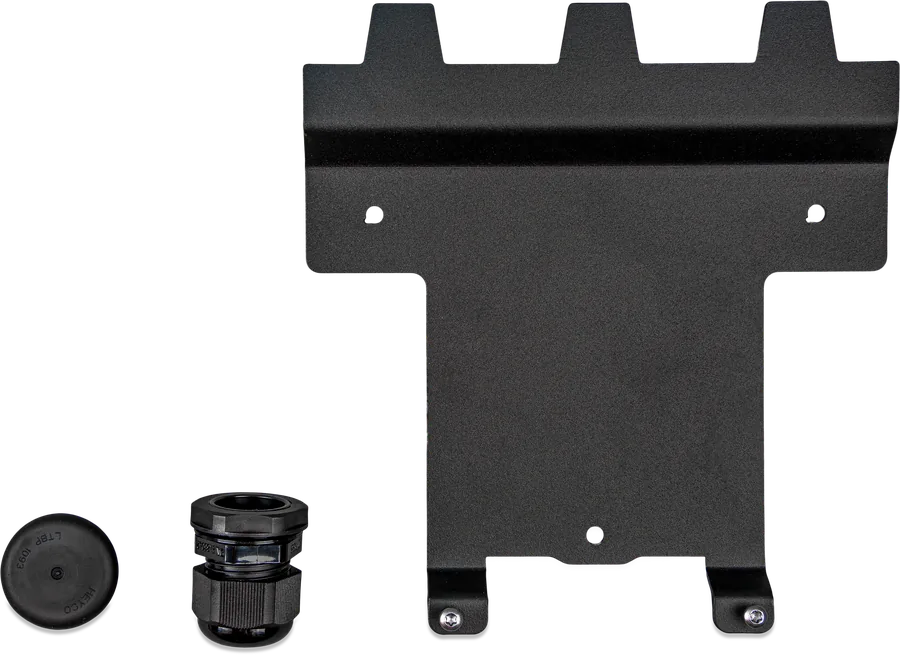
- Cable entry: from below through the 28 mm gland (cable up to 19 mm diameter) or from the rear through the rubber blanking plug with a hole slightly smaller than the cable — then the entry is sealed.
- Mounting: wall or post, on a flat and rigid surface. Mounting plate screws 1–1.2 Nm; hang the station on the plate and fasten it with two screws from the inside, then the front with two screws from below.
- Note the label inside: model, serial number, Wi-Fi password and web password (the same password) and — depending on the production date — the Bluetooth pairing code.
- Keep away from sources of fire and flammable materials. Strong sun on the enclosure can trigger a temperature warning (W-103) or an E-05 error — it is better to choose a shaded location.
Pairing via MQTT
The station connects to the GX device only via Wi-Fi network (2.4 GHz) — both devices must be on the same network and the same subnet. The recommended method is MQTT: the GX then shows the station’s warnings and errors, the station is available remotely via VictronConnect-Remote, and the GX can control it as part of GX Opportunity Loads and Dynamic ESS. Modbus TCP remains an alternative.
- Check the versionsstation firmware from 2.09, GX device from 3.80, VictronConnect from 6.41.
- Enable pairing on the GXSettings → Integrations → MQTT Devices → Activate. Pairing mode lasts 2 minutes; on GX devices with a button you can enable it by pressing the button twice (e.g. with a pen).
- Find the GX from the stationon the station page: General → GX device, or in VictronConnect: Settings → General → GX Device. Enable communication, choose MQTT and press “Discover”.
- Pairselect your GX (the IP address and VRM Portal ID will be filled in), press “Pair” and save. The station will appear in the device list and on the GX overview page.
Discover finds nothing? The network may be blocking mDNS packets — then enter the IP address and VRM Portal ID manually. The station’s Wi-Fi signal should ideally be stronger than −70 dBm. The router should be a certified device compliant with the RED directive.
What to set in VictronConnect
Initial setup (after purchase or after a reset) has three steps: Wi-Fi network (the station’s own access point or Station mode on the home network), new login and password for the station web page (factory default “admin” and the password from the label), maximum charging current 6–32 A. You can do the same in a browser: after connecting to the station’s Wi-Fi, address 192.168.0.1.
- EV Charger position: “Inverter AC in” if the station is before the inverter/charger, “Inverter AC out” if it is after the inverter.
- Autostart (EV Charger autostart): enabled — charging starts when the cable is plugged in; disabled — you must press “Start”. Disabling it protects against charging by other people (the station has no RFID reader).
- Contactor active when charged: closed allows you, for example, to heat or cool the cabin using power from the station instead of the car battery; some cars then report an error.
- Maximum and minimum current: both in the 6–32 A range. The minimum determines how much PV surplus you need in Auto mode.
- Start charging at backup battery SoC and Stop charging at backup battery SoC if off grid — protect the house battery.
- Allow Battery/Grid power for Auto mode with a time limit (Battery/Grid power timeout) — charging at minimum current even when there is no surplus, to reduce constant switching on and off. Whether the energy comes from the battery or from the grid is decided by the inverter.
- Backup battery emulation — only in an installation without a house battery: the station pretends to be a battery so that Auto mode works.
- Overload protection — response to inverter overload and to the grid current limit (described in Functions).
- Energy price per kWh — for calculating the cost and savings of a session. Date and time zone — without them the schedule will not work (warning W-107).
After you press “Stop”, the station first reduces the current to minimum, and the contactor opens after a 2 s delay. You can save the settings to a file and load them on another station.
Errors, warnings, messages
The same code has three forms: in VictronConnect “E-01”, on the GX “#01”, generally “01”. E errors block charging, W warnings inform you of a limitation, N messages explain why a command cannot be carried out.
| Code | Meaning | Action to take |
|---|---|---|
| E-01 | No protective earth conductor (GND not present) | An electrician checks PE and earthing. |
| E-02 | Welded relay contacts | Call an installer. |
| E-03 | CP input short-circuit | Call an installer. |
| E-04 | Residual current | Call an installer. |
| E-05 | Overtemperature | Shade the station from direct sunlight or call an installer. |
| E-06, E-07 | Light sensor, enclosure opening detected | Applies only to stations for the UK market. |
| W-101 | Initial setup not completed | Complete the initial setup. |
| W-102 | Station blocked by the grid operator | Contact the grid operator. |
| W-103 | High temperature, charging not yet interrupted | Shade it from the sun or call an installer. |
| W-104 | No communication with GX, although it is switched on | Same network? Correct IP and VRM Portal ID? Is the station still on the paired list in GX? Repeat pairing. For Modbus TCP: Modbus TCP enabled in GX. |
| W-105, W-106 | Overload detected / overload ongoing | The station reduces current or stops charging; check the inverter load. |
| W-107 | Schedule not working — no time synchronisation | Set the date, time and time zone. |
| W-108 | Current limited by external switch | Function for Germany (§14a EnWG) — the operator may limit the current to 6 A. |
| W-109 | Current limited due to inverter overheating | Check inverter cooling and load. |
| N-301 | Auto mode unavailable | Enable communication with GX. |
| N-302 | No schedule | Add a schedule before selecting Scheduled mode. |
| N-303 | Car not connected — cannot start | Connect the car. |
| N-304 | Charger error | Check and clear error E; call an installer. |
| N-305 | Initial setup not completed | Complete the initial setup. |
| N-306 | Charging will start according to the schedule | To control it manually, switch to Manual mode. |
| N-307 | Overload — cannot start | Wait until the overload has cleared. |
Auto does not detect the connection
Or the station keeps switching between “charging” and “charged”. The CP signal can be the cause. From software 2.02, CP calibration is automatic every time you connect; manual calibration is enabled by setting Modbus TCP register 5133 to 0. Earth impedance is also important.
Station visible on multiple GX devices
On the station page, enable the IP whitelist and enter only the GX that is to control it. Then remove the station from the other GX devices.
Lost password
Factory reset from the station page (Backup & FW) or from VictronConnect. With the DEF button inside (electrician only, station live): 5–15 s — reset only the password and Bluetooth PIN (ring flashes green rapidly), more than 15 s — full reset (flashes blue).
Firmware update
The easiest way is remotely from VRM (requires GX in VRM). Manually: *.evcsup file from Victron Professional — for NS with “C026” in the name, for the display version with “C025” — in the Backup & FW tab. Settings are retained.
Frequently asked questions about EV Charging Station
Does the station need a GX device?
Only for auto mode (charging from PV surplus) — in that case communication with GX is mandatory. In manual mode and with a schedule, the station works without GX. The buttons in VRM and remote access also require GX in the VRM portal.
How much solar power is needed to charge in auto mode?
The minimum charging current is 6 A at 230 V, which is about 1.4 kW of surplus (PV production minus house loads). With a smaller surplus, you can enable “Allow low excess solar power for auto mode” — the grid will make up the missing part. Some cars need more, for example Renault Zoe 10 A.
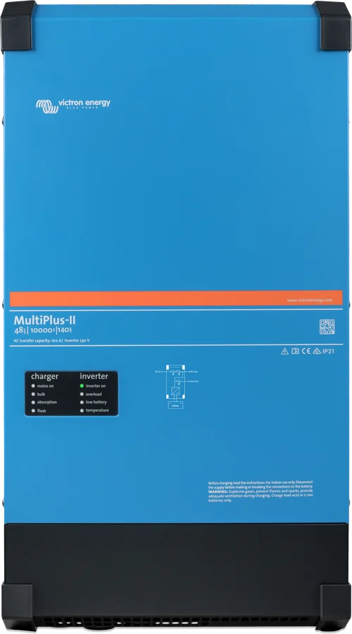
Can the station be connected to the output of a MultiPlus?
Yes — on the inverter/charger AC input (“Inverter AC in”) or on its output (“Inverter AC out”). You must set the position in the station, because it affects how the surplus is calculated. On the inverter output, the car loads the inverter — if it overloads, the station reduces the current or stops charging.
Does the station have RFID or another lock?
It does not have RFID. To stop unauthorised people charging, disable auto start — charging will begin only after pressing “Start” in the app, on the station page, in the VRM widget or in the VRM panel.
Is the cable to the car included?
No. The station has a Type 2 socket (IEC 62196); the NS set includes only the holder for hanging up the cable plug. You choose the cable to suit the car.
Which RCD and which circuit breaker?
A 40 A circuit breaker or fuse, or lower, with a cable sized accordingly (6 mm² recommended). An external RCD is required; Victron recommends type B sized to the power — 40 A for 22 kW charging. Also check local regulatory requirements.
Does the station connect to GX via Ethernet?
No — the station has no Ethernet port. It communicates with GX over 2.4 GHz Wi-Fi (MQTT or Modbus TCP), and with the phone over Bluetooth. GX can be connected to the router by cable — what matters is that both devices are on the same subnet.
Can you have several stations in one system?
Yes. The available power is then shared between the stations.
The light ring is disturbing at night — how do you turn it off?
In the light ring settings (Light Ring), reduce the brightness or set 0% for selected states.
Can the station be controlled via Modbus TCP?
Yes, Victron provides the register list on the product page. However, the manual states that changing settings via Modbus TCP means losing the manufacturer’s support; questions should be directed to the Modifications department on Victron Community.

Manufacturer documentation
Content checked against Victron Energy documentation (datasheets and manuals) — status as of 23 September 2026. Report an error in the content · Correction log