
Victron palette
Node-RED has its own basic set of nodes. Venus OS Large adds the Victron nodes — the node-red-contrib-victron palette. It is installed by default. The nodes work on D-Bus, that is, on the values Venus OS exposes from devices connected to the GX. In a node, you choose the device and parameter; paths with placeholders, such as {tracker}, are automatically expanded by the editor into options available on connected devices.
- Palette update — only together with a new Venus OS Large. The palette cannot be updated from the editor or from the command line. If a newer palette is already available online, you must wait for the next Venus OS Large release — it usually appears soon after the palette update.
- Node descriptions — the project wiki on GitHub describes each node and its paths (Input nodes, Output nodes and Virtual devices pages). The paths and values on this page come from it.
- Other palettes — additional nodes, such as dashboard, are installed from the internet to the GX data partition, so they remain after a Venus OS update. Required spare space: first opening.
Node types
The wiki divides Victron nodes into input, control and virtual devices, and separately lists two custom nodes.
| Type | What it does | How many |
|---|---|---|
| Input | Subscribe to a D-Bus value and send a message when it changes. | 33 |
| Control | Write the value sent in msg.payload to the device. | 18 |
| Custom | Read and write any service and path found on D-Bus — for anything not covered by the other nodes. For example, the built-in GX restart example flow uses the Custom Control node. | 2 |
| Virtual | Virtual Device and Virtual Switch create a device on D-Bus; Inject Notification and Inject Event send a notification to the GX or an event to VRM. | 4 |
Full list of device nodes
All 33 input nodes; 18 of them also have a control version (marked “Control” in the wiki). Descriptions according to the wiki.
| Node | Reads from | Control |
|---|---|---|
| Accharger | AC chargers | yes |
| Acload | AC loads measured by an energy meter with the “AC load” role | — |
| Acsystem | service managing Multi RS and future inverter/chargers | yes |
| Alternator | BMV in monitor mode with type “Alternator”, or an alternator controller connected to Venus OS | yes |
| Battery | battery state: SoC, voltage, current, alarms, history | yes |
| Dcdc | Orion XS | yes |
| Dcload | BMV in monitor mode with type “load” | — |
| Dcsource | BMV in monitor mode with type “source” | — |
| Dcsystem | DC load measurement in the installation | — |
| Dess | Dynamic ESS | yes |
| Digitalinput | GX digital inputs — only when enabled in Settings → I/O → Digital inputs | — |
| Ess | ESS energy storage system | yes |
| Ev | electric vehicles — integrated through VRM and virtual in Node-RED | — |
| Evcharger | EV charging station | yes |
| Fuelcell | fuel cell | — |
| Generator | generators started by relay and Fischer Panda generators | yes |
| Gps | GPS position | — |
| Gridmeter | grid meter | — |
| Inverter | inverter | yes |
| Meteo | solar radiation, temperature and wind sensors | — |
| E-drive | electric drive (motordrive service) | — |
| Multi | Multi RS | yes |
| Pulsemeter | pulse meter — digital input configured as “Pulse meter” | — |
| Pump | pump | yes |
| Pvinverter | PV inverter | yes |
| Relay | GX relays, as well as charger and Multi RS relays | yes |
| Settings | settings — currently mainly Carlo Gavazzi meters | yes |
| Solarcharger | MPPT solar charge controller | yes |
| Switch | USB-connected I/O extender | yes |
| System | aggregated system data (com.victronenergy.system service): battery, PV, AC consumption, grid, generator | — |
| Tank | tank level sensors | — |
| Temperature | temperature sensors — e.g. a wired probe or Ruuvi via Bluetooth; also temperature from tank sensors | — |
| Vebus | VE.Bus devices, e.g. MultiPlus and Quattro | yes |
When the node sends a message
- On every value change — this is the input node’s basic behaviour.
- With “only changes” selected — only when the value changes.
- Without “only changes” — additionally, every 5 s the node sends the current value, even if it has not changed.
- Value at a fixed interval — use a change node to save
msg.payloadin context (flow.orglobal.), and an inject node to read it at the chosen interval. That is how the built-in “Only Messages at Regular Intervals” example works. - Context after a restart — by default, context is kept only in RAM and is lost after a GX restart or a power outage. Disk writes are enabled in
/data/home/nodered/.node-red/settings-user.js(localfilesystemstorage; in the manual’s example, saved every 300 s). Do not save too often, to avoid wearing out the flash memory.
How the control node works
The Control node writes the value from msg.payload to the device. Parameters with a list of values (enum) are set by number — in Victron examples, the inject node sends, for example, the number 3 to the Vebus Control node to switch on the inverter/charger. The values for each path are in the table below and in the wiki.
- Scheduling — the inject node can send a value at a fixed time, on selected days, or every few minutes within a defined time window. Node-RED uses the time zone set in Remote Console; after changing it, you need to restart Node-RED.
- State keeping — the “Event Based Scheduling” example links the Vebus input node (
/Mode) with the control node so that, during scheduled hours, it keeps the selected mode even if someone changes it by mistake. - Special schedules — for holidays, random offset, or dusk and dawn, Victron recommends the additional node-red-big-timer node (Manage palette → Install).
Useful paths
Each parameter has its own D-Bus path. The editor expands placeholders in paths to values available in the connected devices:
| Symbol | Meaning |
|---|---|
{type} | switch output type: output_1, output_2, pwm_1, relay_1, etc. |
{tracker} | PV tracker number: 0, 1, 2, 3 |
{phase} | AC phase: 1, 2, 3 (L1, L2, L3) |
{day} | history day: 0 = today, 1 = yesterday |
{input} | AC input: 1, 2 |
{channel} | DC channel: 0, 1 |
{index} | sequential number: 0, 1, 2, 3, etc. |
Selected paths from the wiki — for automation based on battery state, PV production and inverter mode:
| Node | Parameter and path | Values |
|---|---|---|
| Battery | state of charge (%) — /Soc | number |
| Battery | battery voltage (V) — /Dc/0/Voltage; current (A) — /Dc/0/Current | number |
| Battery | starter battery voltage (V) — /Dc/1/Voltage | number |
| System | battery SoC (%) — /Dc/Battery/Soc; power from MPPT controllers (W) — /Dc/Pv/Power | number |
| Solarcharger | PV power (W) — /Yield/Power; PV voltage (V) — /Pv/V | number |
| Solarcharger, Accharger (Control) | charger on/off — /Mode | 1 On, 4 Off |
| Vebus (input and Control) | switch position — /Mode | 1 Charger Only, 2 Inverter Only, 3 On, 4 Off |
| Vebus (Control) | AC input current limit (A) — /Ac/In/{index}/CurrentLimit | number |
| Ess (Control) | minimum discharge SoC (%) — /Settings/CGwacs/BatteryLife/MinimumSocLimit; grid set-point (W) — /Settings/CGwacs/AcPowerSetPoint | integer |
| Generator (Control) | generator start — /Start | 0 Stop, 1 Start |
| Relay (input and Control) | GX relay — /Relay/{relay}/State; charger relay (in the wiki “Relay on the charger”) or Multi RS — /Relay/0/State | 0 Open, 1 Closed |
| Digitalinput | input state — /State | from 0 low to 11 stopped, depending on the input type |
| Tank, Temperature | level (%) — /Level; temperature (°C) — /Temperature | number |
Relays — what to set first
For Node-RED to switch a relay, you must first set it to manual control — most often in VictronConnect. Then the Relay Control node operates the relay: 1 closes the contact (Closed), 0 opens it (Open).
| Relay | What to set | Node-RED |
|---|---|---|
| GX device | relay function “Manually controlled” in the GX menu; Cerbo GX relays — on the Cerbo GX board | yes |
| BMV | REM relay option (Remote Controlled) in VictronConnect | yes |
| Lynx Shunt VE.Can | relay function “Manual control” in the GX menu | yes |
| MPPT solar charge controller | relay operating mode “manual control” in VictronConnect; only larger models have a relay | yes |
| RS series (inverter, Multi RS) | relay manual control in VictronConnect | yes |
| Smart IP43 Charger | remote control mode in VictronConnect. The relay is powered only when the charger is on — it does not work when it is off with AC connected (230 V and 120/240 V models). This is the only charger with a controllable relay. | yes, with a limit |
| Lynx Smart BMS | — | no |
| Multi, Quattro (VE.Bus) | alarm relay and AC-out-2 contactor — Victron does not plan to make them available for remote control | no |
- Generator relay — set it in the GX console to the “Generator” function, and send start and stop with the Generator Control node (
/Start: 1 Start, 0 Stop). Fischer Panda generators are started directly by the Generator node via D-Bus. - Switch on the dashboard — the “Relay Switching” example controls a relay from the dashboard. To make the switch also show changes made elsewhere, for example in the GX menu, connect the Relay input node to the switch input as well. The node-red-dashboard palette is required — see dashboard and remote access.
- Ready-made flow — relay switched on and off according to battery state: step-by-step example.
Virtual devices
A virtual device lets you connect hardware or a data source to GX that Victron does not support. Once created in Node-RED, it appears in GX and behaves like a real Victron device — also in the VRM portal. Manual examples: weather from an API as a virtual weather station, calculated import and export as a virtual grid meter, position from GPSd as a virtual GPS, LoRa or MQTT sensors as a virtual tank or temperature sensor.
- Current Venus OS. Update the GX device to the latest version.
- Virtual Device node. Add it to the flow and select the device type.
- Data. Connect a data source or control logic. Send
msg.payloadto the node as an object: the keys are D-Bus paths without the leading slash, and the values are readings, for example{"Dc/0/Voltage": 48.2, "Dc/0/Current": 12.5, "Soc": 85}.
- D-Bus name:
com.victronenergy.<typ>.virtual_<node id>. - Disconnect and reconnect:
msg.connected = falsedisconnects the device and releases the D-Bus service name;msg.connected = truerestores it. - Output: one port — passes through the original message with
msg.connectedset to the current D-Bus connection state.
| Type (wiki) | D-Bus service and example paths |
|---|---|
| AC Load | com.victronenergy.acload — /Ac/L1/Current, /Ac/Energy/Forward |
| Battery | com.victronenergy.battery — /Dc/0/Voltage, /Dc/0/Current, /Dc/0/Power, /Dc/0/Temperature |
| DC Load | com.victronenergy.dcload — /Dc/0/Voltage, /Dc/0/Current, /Dc/0/Power |
| E-drive | com.victronenergy.motordrive — /Dc/0/Power, /Controller/Temperature, /Coolant/Temperature |
| Electric Vehicle | com.victronenergy.ev — /Soc, /TargetSoc, /ChargingState, /Ac/Power |
| Energy meter | com.victronenergy.energymeter — /Ac/Power, /Ac/Energy/Forward, /Ac/Energy/Reverse |
| Generator | com.victronenergy.genset or com.victronenergy.dcgenset — /Start, /EnableRemoteStartMode, /Engine/CoolantTemperature |
| GPS | com.victronenergy.gps — /Position/Latitude, /Position/Longitude, /Fix |
| Grid meter | com.victronenergy.grid — /Ac/Power, /Ac/Energy/Forward, /Ac/Energy/Reverse |
| Meteo | com.victronenergy.meteo — /Irradiance, /ExternalTemperature, /WindSpeed |
| Pulse meter | com.victronenergy.pulsemeter — /Count, /Aggregate |
| PV inverter | com.victronenergy.pvinverter — /Ac/Power, /Ac/Energy/Forward, /Ac/PowerLimit |
| Tank sensor | com.victronenergy.tank — /Level, /Capacity, /FluidType |
| Temperature sensor | com.victronenergy.temperature — /Temperature |
Virtual Switch
Creates a switch without a physical relay — for example, for an IoT switch with Tasmota software, which the flow controls according to battery state. According to the manual, it appears in the Switch panel of the new Venus OS interface, can be turned on and off like a real switch, and its state is stored in the GX device and can survive a restart.
- Control:
{"SwitchableOutput/output_1/State": 1}turns it on,{"SwitchableOutput/output_1/Dimming": 75}sets dimming to 75%.msg.connected = falsedisconnects the switch. - 11 types: On/Off (0 off, 1 on), Dimmable (on/off and dimming 0–100%), Temperature setpoint (thermostat slider in °C), Stepped, Basic slider, Dropdown, Numeric input, Three state (0 Off, 1 On, 2 Auto), RGB colour wheel, CCT wheel and RGB+White dimmer.
- Outputs: port 1 passes the message with
msg.connected; port 2 sends the new state when it changes; port 3 sends the new dimming value or setpoint (types with dimming, steps, numbers and RGB).
Notifications and events
| Feature | Inject Notification | Inject Event |
|---|---|---|
| Where shown | Venus OS notification centre, in the GX interface | VRM portal: Diagnostics → Event logs |
| D-Bus target | com.victronenergy.platform, /Notifications/Inject | com.victronenergy.logger, /EventLogging/Inject |
| Severity | 0 Warning, 1 Alarm, 2 Information | 0 Warning, 1 Critical, 2 Info |
| Content | msg.payload; title from the configuration or msg.title, type from the configuration or msg.type (number or “warning”, “alarm”, “info”) | msg.payload; source name (App) from the configuration or msg.app, severity from the configuration or msg.severity (number or “warning”, “critical”, “info”, case-insensitive) |
| Limits | title up to 100 characters, content up to 500 — longer ones are truncated | — |
| Output | original message with msg.notification added | original message with msg.event added |
Built-in examples
In the editor: menu in the top right corner → Import (or Ctrl+I) → Examples → node-red-contrib-victron. The same examples are in the wiki on the Example Flows page. Some of them require extra palettes — most often node-red-dashboard.
| Example | What it shows |
|---|---|
| Trigger Based Scheduling | turning an inverter/charger on and off at fixed times (inject + Vebus Control) |
| Event Based Scheduling | maintaining the selected inverter mode during scheduled hours |
| Combining Inputs / Night Time Rate Battery Charging | SoC from the Battery node selects the Quattro mode: below 25% charging at any time; 25–50% charging at night, and by day running from the battery (Inverter Only); above 50% running from the battery |
| Brightness-Based Lamp Control | lamp on a relay: switch on when the PV voltage from the SmartSolar charge controller is below 5 V for 60 s; switch off after 30 min when it is no longer dark |
| Temperature Dashboard | temperature from the sensor on the dashboard, rounded to one decimal place |
| Location Based Scheduling | relay at dusk and dawn based on position from a USB GPS (BigTimer node) |
| Monitor Disk Usage, MQTT Disk Space Monitoring | GX storage usage — via the df command or via MQTT |
| Relay Switching | relay switched from the dashboard |
| Solar Forecasting | PV production forecast from the forecast.solar service |
| Threshold Control | output switched on above the ON threshold and off below the OFF threshold, with a delay — from a Victron webinar |
| Load Shedding and MinSOC | minimum SoC in ESS set according to grid outage warnings (EskomSePush API, South Africa) |
| Only Messages at Regular Intervals | value sent at a fixed interval by context |
| Run Generator at Certain Time | every day at 18:00: when SoC is below 50%, the generator runs for 45 min |
| Venus Reboot | restart the GX device from the flow with the Custom Control node |
Where the sources differ
- Virtual device types. The Venus OS Large manual (section 5.8) lists 9: Battery, Generator, GPS, Grid meter, Meteo, Motor drive, PV inverter, Tank sensor and Temperature sensor. The wiki (Virtual devices) lists 14: it adds AC Load, DC Load, Electric Vehicle, Energy meter and Pulse meter, and “Motor drive” appears as E-drive (service com.victronenergy.motordrive). Which types are available to you is shown by the type list in the Virtual Device node.
- Where the virtual switch appears. Instructions: in the switch panel of the new Venus OS interface. Wiki: Venus OS sees it as a connected Cerbo GX I/O extender, and the GX interface lets you control it.
- How often messages arrive. FAQ Q9 and the “Only Messages at Regular Intervals” example: on every change, and without “only changes” additionally every 5 s. The “Event Based Scheduling” example: by default every 5 s, with changes sent immediately — “about once a second”.
- Times in “Trigger Based Scheduling”. Description: turn on at 6:00, turn off at 22:00. In the flow itself, the node “Trigger 'ON' at 22:00” sends 3 (On) at 22:00, and “Trigger 'OFF' at 6:00” sends 4 (Off) at 6:00. After importing, check the times and values in the inject nodes.
- Updating the palette. Section 5.3 and FAQ Q2: you cannot update the Victron palette from the editor or the command line — only through the new Venus OS Large. Section 5.6 says more generally that if you install a newer version of the palette than the factory one, Node-RED will use the newer version. The Victron palette is stated plainly in Q2: only the new Venus OS Large.
- Placeholders. The wiki legend lists {type}, {tracker}, {phase}, {day}, {input}, {channel} and {index}, but the path descriptions also use {relay} (
/Relay/{relay}/State), {line} (/Ac/Consumption/{line}/Powerin the System node) and {historyDay} (/History/Daily/{historyDay}/Yieldin the Solarcharger node).
Control nodes change inverter mode, current limits, ESS settings and relay state as soon as the flow is deployed (Deploy). Victron does not support installations where Node-RED is used for advanced solutions — test a new flow during installation under supervision. If a flow overloads the GX device, you can disable it in safe mode: safe mode and restart.
Devices this applies to
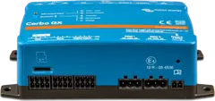 Cerbo GXSystem control centre and gateway to the VRM portal.
 Ekrano GXGX centre with built-in 7″ touchscreen.
Sources
- node-red-contrib-victron wiki — Available nodesgithub.com · EN
- node-red-contrib-victron wiki — Input nodesgithub.com · EN
- node-red-contrib-victron wiki — Output nodesgithub.com · EN
- node-red-contrib-victron wiki — Virtual devicesgithub.com · EN
- node-red-contrib-victron wiki — Example Flowsgithub.com · EN
- Venus OS Large image: Signal K and Node-RED — sections 2, 5.3–5.8, FAQ Q2, Q9, Q11victronenergy.com · EN