
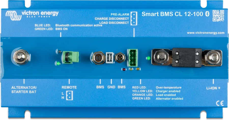
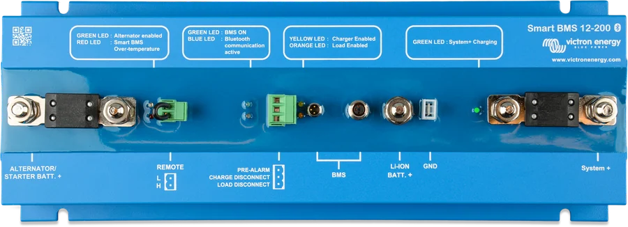
Smart BMS CL 12-100 from above — ALTERNATOR/STARTER BAT and LI-ION+ terminals, remote, BMS, pre-alarm, LEDs and MEGA fuse connectors
Smart BMS CL 12/100
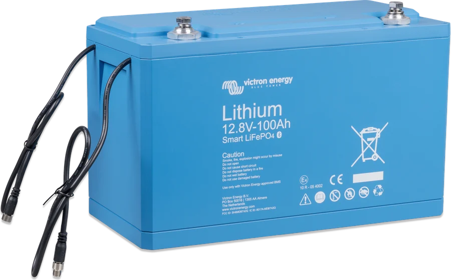
BMS for Lithium Battery Smart 12.8 V batteries in vehicles and boats with a 12 V alternator. It monitors each cell and uses the control outputs to switch off chargers and loads if cell voltage is too low or too high, or if the battery overheats. It has a separate alternator input with a current limiter (Current Limiter): current flows only from the alternator to the lithium battery, and its value is set by the fuse — so any 12 V alternator can be safely connected to a lithium battery.
- 12 V
- alternator up to 100 A
- up to 20 batteries (84 kWh)
- Load / Charge disconnect, pre-alarm
- Bluetooth, IP65
Lithium battery in a vehicle with an alternator
A lithium battery has very low internal resistance and draws as much current from the alternator as it can supply. According to Victron, most 12 V alternators overheat and fail when run at full power for more than 5 minutes. Smart BMS CL solves this on the Alternator/Starter Batt+ port: it electronically limits the current to about 90% of the fitted fuse rating and allows it to flow only one way — from the starter battery to the lithium battery, and only when the voltage rises above 13 V. So the lithium battery cannot discharge the starter battery, or vice versa.
The current for loads and other chargers does not flow through the BMS — you control them through the Load disconnect and Charge disconnect outputs. This is what distinguishes it from the Smart BMS 12/200, which has a system port for loads and chargers.
- up to 20 Lithium Battery Smart 12.8 V batteries — up to 84 kWh; the battery BMS wires are daisy-chained,
- surges and transients at the input are reduced to a safe level,
- configuration and live data via Bluetooth in VictronConnect, including Instant Readout,
- IP65 (electronics), −40…+60 °C, 1.6 kg.
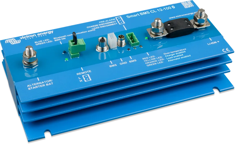
Load disconnect, Charge disconnect, pre-alarm, remote
Load disconnect
Normally high (battery voltage − 0.1 V), goes high impedance when cell voltage is at risk of becoming too low (factory setting 2.8 V, set in the battery). Max. 10 mA. Controls the remote input of BatteryProtect, inverter, DC-DC converter.
Charge disconnect
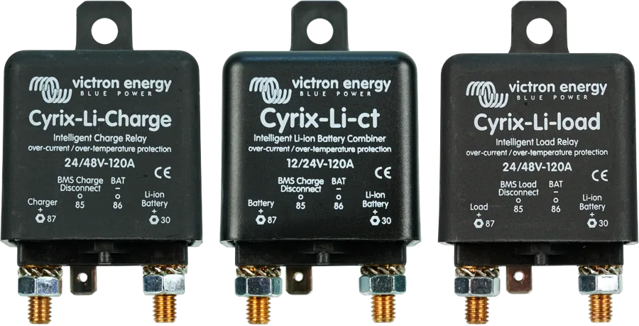
Normally high, goes high impedance if there is a risk of cell overvoltage or overheating. Max. 10 mA. Controls the remote of a charger (e.g. Smart IP43), Cyrix-Li-Charge, Cyrix-Li-ct or BatteryProtect. Not suitable for powering a relay coil.
Pre-alarm
Normally low, goes high (max. 1 A, no short-circuit protection) when cell voltage is low (factory setting 3.1 V) — at least 30 s before the loads are disconnected. Relay, LED or buzzer; continuous or intermittent signal.
Remote on/off (L, H)
Enabled when L and H are shorted (factory loop), when L is pulled to negative (< 5 V) or when H is > 3 V. Switches off charging from the alternator only or — depending on the setting — the whole system. A loop or switch between L and H is required.
The fuse sets the alternator current
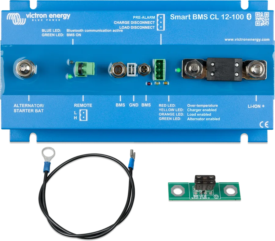
The alternator port fuse also works as a shunt — the BMS measures current on it and limits it according to the table. The correct fuse protects a small lithium battery from excessive charge current, and the alternator from overload with a large battery bank. The kit includes a 100 A MEGA fuse and an ATO holder with two 7.5 A fuses.
| Fuse | Max. alternator current |
|---|---|
| 125 A | 100 A |
| 100 A | 90 A |
| 80 A | 60 A |
| 60 A | 50 A |
| 2 × 30 A (ATO) | 40 A |
| 2 × 20 A (ATO) | 25 A |
| 2 × 15 A (ATO) | 20 A |
| 2 × 10 A (ATO) | 12 A |
| 2 × 7.5 A (ATO) | 9 A |
Below 40 A, use the supplied ATO holder with the pair of fuses according to the table. Set the same fuse in VictronConnect (Fuse type) — otherwise the current reading as a percentage will be incorrect. The description “about 90% of the fuse rating” does not exactly match the table at lower values (e.g. 80 A → 60 A) — the manual table applies.
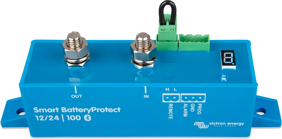
Campervan or boat with Smart BatteryProtect
According to the example in the manual: alternator and starter battery to the Alternator/Starter port, Lithium Smart battery to Li-ion+, loads via Smart BatteryProtect controlled from Load disconnect. Schematic diagram.
- AlternatorStarter battery positive to ALTERNATOR/STARTER BAT.
- Li-ion+To the positive terminal of the Lithium Battery Smart battery.
- BMS cableFrom the batteries (daisy-chained) to the BMS port.
- Load disconnectTo the remote of Smart BatteryProtect or inverter.
- Charge disconnectTo the remote of chargers and controllers (if needed, via an interface cable).
Step-by-step installation
- LocationBest on a vertical surface; cables as short as possible.
- FuseSelect the alternator port fuse according to the table.
- DisconnectDisconnect the cables from the starter battery negative terminal and remove the remote on/off plug.
- Current cablesStarter battery positive to ALTERNATOR/STARTER BAT, lithium battery positive to LI-ION+ (negatives still disconnected). M8 fuse nuts: 10 Nm.
- BMS cablesDaisy-chain between the batteries, ends to the BMS port; use 3-pin M8 extension leads if needed.
- BMS groundConnect the supplied ground cable to the negative of the lithium battery and the starter battery — with a 300 mA–1.3 A fuse (BMS consumption + outputs × 1.25; for example 16 mA + 10 mA + 10 mA + 1 A = 1,036 mA × 1.25 = 1.3 A).
- RemoteReinsert the remote plug with the loop or switch between L and H.
After BMS cut-off, about 1 Ah remains in the battery for every 100 Ah of capacity. Even 10 mA of continuous load can damage a 200 Ah battery left in this state for more than 8 days. Charge it immediately, and if the system will stand unused for longer, disconnect the battery with a switch or fuse. Victron recommends switching the system off earlier — for example with a BMV relay controlling the BMS remote on/off at a set SoC.
Units manufactured up to and including batch HQ2109 (serial number on the back) are powered from the ALTERNATOR/STARTER BAT port, later ones — from the LI-ION port.
Configuration in VictronConnect
- Fuse type: fuse matched to the fitted one — needed to see alternator current as a percentage.
- Battery Pre-alarm usage: “Pre-alarm not available” for batteries without a pre-alarm function; factory setting is “Use pre-alarm”.
- Pre-alarm: continuous or intermittent signal.
- Battery charge limit: 13.0–15.3 V, usually 14.2 V for Lithium Battery Smart. Once reached, the BMS interrupts charging from the alternator port; it resumes when the voltage has been 0.5 V lower for 10 s.
- Remote on/off function: “Disable alternator” (factory setting — switches off alternator charging only, BMS remains active) or “Switch everything off” (switches everything off, including outputs; this is a system-wide switch).
Documentation discrepancy: with “Switch everything off” the manual states consumption below 0.01 W, while the technical data states 5 mA with remote off (at 13 V that is about 0.065 W). In the manual’s technical data, the charging start threshold is written as “> 13 A” instead of 13 V.
Which devices require an interface cable
| Device | BMS output | Connection |
|---|---|---|
| Phoenix VE.Direct, Phoenix Inverter Smart | Load disconnect | directly to the H terminal of the 2-pin connector |
| Tr DC-DC chargers with remote, Orion 12/24-20 | Load disconnect | directly to the right-hand terminal of the 2-pin connector |
| BatteryProtect / Smart BatteryProtect | Load disconnect | terminal 2.1 (right) / pin H |
| Cyrix-Li-load | Load disconnect | Cyrix control input |
| Phoenix VE.Bus inverters and Inverter Compact from 1200 VA | Load disconnect | reversing remote on/off cable (ASS030550100 or -120) |
| SmartSolar MPPT from 150/45 and from 250/60 | Charge disconnect | directly to the + terminal or H terminal of the 2-pin connector |
| BlueSolar MPPT (except 150/70 and 150/80 CAN-bus), SmartSolar MPPT up to 150/35 | Charge disconnect | non-inverting VE.Direct cable (ASS030550320) |
| Smart IP43 | Charge disconnect | H terminal of the 2-pin connector |
| Skylla-TG / Skylla-i | Charge disconnect | non-inverting cable ASS030550200 / Skylla-i cable ASS030550400 |
| Other chargers | Charge disconnect | via Cyrix-Li-Charge or connected on the BMS primary side |
| MultiPlus 500–1600 VA, MultiPlus Compact 800 VA–2 kVA | both | Smart BMS CL 12/100 to MultiPlus cable (ASS070200100) |
| MultiPlus-II, MultiPlus from 3 kVA | both | two reversing remote cables (ASS030550100) and configuration according to the document about connecting lithium batteries to Multi |
According to Appendix A of the manual. With MultiPlus 500–1600 VA both BMS outputs must be high for the MultiPlus to operate; after cut-off due to low voltage, start the alternator or the charger on the BMS primary side.
Errors, alarms, warnings
| Code | Meaning | Action to take |
|---|---|---|
| E-B30 | Calibration error | Irreparable — replace the BMS with the supplier. |
| E-B31 | Configuration error | Factory reset (Settings → More options → Reset to defaults), disconnect the power for 3 minutes, then configure again. |
| E-B32 | Battery BMS cable disconnected or damaged | Check the cables; for a battery without pre-alarm, disable pre-alarm in the settings. From software 1.08 this error is no longer reported. |
| E-B33 | Reference voltage error | Irreparable — replace the BMS with the supplier. |
| A-B11 | Low voltage | Switch off loads, charge the battery, check the charging system. |
| A-B15 | BMS overtemperature | Check the fuse rating, connections and cable cross-sections; move the BMS to a cooler location. |
| W-B12 | Low-voltage warning | Urgently switch off loads and charge the battery. |
LEDs (from left)
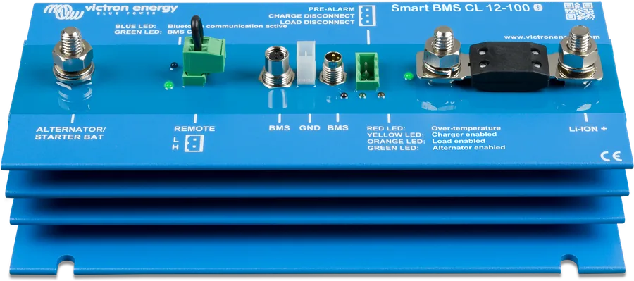
1 green — BMS active; 2 blue — flashing: Bluetooth transmitting, on: connected; 3 red — BMS overtemperature; 4 yellow — Charge disconnect enabled; 5 orange — Load disconnect enabled; 6 green — alternator charging.
Frequently asked questions about Smart BMS CL 12/100
Does load current flow through Smart BMS CL?
No. Only alternator current flows through the BMS (max. 100 A). Loads and chargers are connected directly to the battery, and switched off through the Load and Charge disconnect outputs — for example by a Smart BatteryProtect, inverter remote, Cyrix-Li-Charge.
Smart BMS CL 12/100 or Smart BMS 12/200?
Both are for Lithium Battery Smart 12.8 V batteries. The CL limits only alternator current to 100 A; the 12/200 also has a system port through which loads and chargers flow. Details on the Smart BMS 12/200 datasheet.
Does it work with Lithium NG batteries?
Smart BMS CL is specified for Lithium Battery Smart 12.8 V batteries. Lithium NG batteries use NG series BMS units, for example smallBMS NG.
Why is the alternator not charging the lithium battery?
Charging starts only above 13 V at the alternator port; it is also disabled by remote (with “Disable alternator” selected), reaching the Battery charge limit, a BMS signal, or overheating. Check the sixth green LED — “alternator charging”.
Do I need a DC-DC charger instead of Smart BMS CL?
Smart BMS CL protects the alternator and the battery, but does not control the charging algorithm — the battery gets alternator voltage up to the set limit. With a smart alternator (Euro 5/6), a DC-DC charger is better: Orion XS or Orion-Tr Smart.
Manufacturer documentation
Content checked against Victron Energy documentation (datasheets and manuals) — status as of 23 September 2026. Report an error in the content · Correction log