
01When to use VEConfigure and when VictronConnect
Most MultiPlus and Quattro settings can now be changed in VictronConnect (also via MK3-USB, and also on macOS and Android). VEConfigure is still needed for:
- Assistants — including ESS, PV inverter support, generator start and stop (VE.Bus Assistants),
- Virtual Switch — a software relay based on voltage, load and SoC,
- changing the grid code,
- the lithium battery wizard requiring an Assistant and the MultiPlus-II external current sensor,
- systems with devices with old and new microcontrollers, and devices with firmware older than 415, which VictronConnect does not fully support.
Victron provides VEConfigure for trained installers and distributors — incorrect configuration can permanently damage the system.
02Installation and connection
VEConfigure 3 is part of the VE Configuration tools package (the VECSetup_B.exe installer from Victron’s downloads page). The package also includes VE.Bus Quick Configure and VE.Bus System Configurator (parallel and 3-phase systems) as well as VEFlash. The programme checks for its own updates and those of the Assistants on start-up when the computer has internet access.
| What you need | Details |
|---|---|
| Computer | Windows — VEConfigure is only available for this system. On macOS and Android, use VictronConnect (without Assistants, Virtual Switch and grid code). |
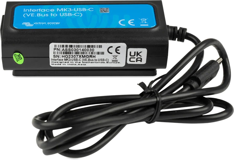
| Interface | MK3-USB (ASS030140000); the older MK2-USB also works with VEConfigure. |
| Cable | straight-through (not crossed) RJ45 UTP cable, factory-crimped — hand-crimped ones often cause problems, even if they work in a computer network. |
| Driver | Windows with internet will download it automatically. Without internet, install the driver first (menu Special → USB Drivers or the “VE.Direct/MK3 USB drivers” installer) and only then connect the interface. |
| Device power | the device must be powered and switched on: MultiPlus and Quattro from AC mains or from the battery, Multi Compact and inverters from the battery, chargers from AC mains. |
- Connect the MK3-USB to the device’s VE.Bus port and to the computer.
- Start VEConfigure 3, Port selection → Com Port → Auto detect.
- The programme will read the settings automatically and open the General tab.
Without a device you can practise: Port selection → Fake target with full options and select the system voltage. The Virtual switch and Assistants tabs are then visible at the same time. Help for each field: Help → What is this? (Ctrl+H).
03Reading, sending and settings files
- Get settings — reads settings from the device. This happens automatically after connection; manually, you can use it to discard unsent changes.
- Send settings — only this button sends changes to the device. The programme asks whether to send everything or only changed items. In parallel and 3-phase systems, start VEConfigure from VE.Bus System Configurator or Quick Configure — then it will also ask which devices to send to.
- Backup: File → Save creates a
.VSCfile for reloading, and Export creates a.txtfile readable in a text editor. Make both backups before every firmware update — the update erases settings. - Factory settings: Defaults → Set all settings to default, then Send settings.
04General tab
| Setting | What it does |
|---|---|
| System frequency | output frequency in inverter mode: 50 or 60 Hz |
| Shore current / AC input current limit | maximum current from the AC input; overridden by a GX device or panel if connected |
| Overruled by remote | ticked: the input limit can be changed by GX or Digital Multi Control (boat, campervan, campsite hook-up); unticked: fixed limit, typically in a home installation and on a generator input |
| Dynamic current limiter | for small inverter generators: generator load rises gradually so the engine has time to respond. Factory default: off |
| External current sensor | external current sensor for MultiPlus-II |
| Battery monitor | built-in VE.Bus battery monitor (capacity, SoC after bulk, charge efficiency) — required for SoC-dependent functions |
How to choose the input limit for shore power and how PowerAssist works is calculated in the current limit calculator.
05Grid tab and grid code
- Country grid code — each country has its own requirements for grid-connected equipment (loss of mains detection, voltage and frequency thresholds). Changing the code and disabling LOM require a password from the distributor. You cannot change the grid code in VictronConnect.
- The fact that VEConfigure shows a code for a given country does not mean that the model is approved there — check the certificates (for example, in Germany, only MultiPlus-II can operate without an external ENS).
- In ESS the code must be set, even without exporting energy to the grid — with code “None” the system will not power loads from the battery when the grid is present.
- Accept wide frequency range — wider input frequency range (45–65 Hz), mainly for generators.
- AC input voltage thresholds (MultiPlus-II factory setting 180–270 V). With synchronous generators with AVR (usually from 10 kVA), Victron recommends raising the lower threshold to 220 V.
- UPS function — enabled by default: transfer to inverter with virtually no interruption. Turn it off if the MultiPlus does not synchronise with the generator or keeps switching to inverter.
06Inverter tab
- Output voltage — usually 230 V (range 210–245 V).
- Ground relay — connects N to PE in inverter mode so residual-current devices work (earthing and RCD).
- DC input low shut-down / restart / pre-alarm — inverter shutdown, restart (at least 1 V higher than shutdown) and warning voltages. Set according to the battery manufacturer. Pre-alarm is offset relative to restart, so changing the thresholds also changes its value. With ESS these fields are ignored — they are replaced by the dynamic cut-off from the ESS assistant.
- AES — reduces no-load consumption (by about 20% in the MultiPlus-II); turn it off with loads with a high inrush current. Search mode reduces consumption further (by about 70%) — the inverter switches off with no load and checks every 2 s whether anything has switched on (MultiPlus-II factory setting: off below 40 W, on from 100 W).
- PowerAssist — when the loads draw more than the input limit, the inverter adds current from the battery. When enabled, it enforces a minimum input limit depending on the model (MultiPlus-II 3 kVA: 4 A, 5 kVA: 6 A, 8–15 kVA: 11 A). Leave Boost factor at 2 unless Victron advises otherwise.
07Charger tab
- Absorption and float voltages, charge current — MultiPlus-II factory setting: 14.4 / 28.8 / 57.6 V and 13.8 / 27.6 / 55.2 V (Victron Gel Deep Discharge profile). For lead-acid batteries, charge current of about 10–20% of capacity. Select the battery type from the list or enter the battery manufacturer’s values.
- Lithium batteries — disables temperature compensation and changes the bulk restart threshold (float − 0.2 V instead of − 1.3 V, for 12 V).
- Charge curve — Adaptive (recommended) or Fixed; Repeated absorption (factory setting 1 h every 7 days) and maximum absorption time.
- Storage mode — after 24 h in float, the voltage drops lower (MultiPlus-II: 13.2 / 26.4 / 52.8 V). Stop after excessive bulk — switches the charger off if absorption is not reached within 10 h.
- Weak AC — for weak sources with a distorted waveform; reduces maximum charge current by about 20%. Use only when the charger hardly charges from the generator at all.
With a battery with a BMS on CAN-bus and DVCC enabled, all charger settings are overridden by the battery (DVCC). In ESS, the MPPT chargers charge according to the curve set in VEConfigure.
08Virtual Switch
Virtual Switch controls the multifunction relay (potential-free contact) or the AC input relay — for example, it ignores the grid or starts the generator according to battery voltage, load and SoC. “ON” conditions take priority over “OFF”; time −1 disables a condition, 0 means operation without delay.
Generator start example: Usage tab → Use VS to control multifunctional switch; ON conditions: battery voltage below the threshold (for example, 11.75 V) or load above the threshold (for example, 1,000 W); minimum run time (for example, 30 min) in VS options. Do not use the alarm here — it would switch the inverter off before the generator starts.
The Virtual Switch and Assistants tabs depend on the firmware: 1xx has Virtual Switch only, 2xx and 3xx have Assistants only, 4xx (new microcontroller) has both. VictronConnect has some Virtual Switch functions under “AC input control”.
09Remote VEConfigure via VRM
You can change MultiPlus and Quattro settings remotely — including assistants and in parallel and 3-phase systems.
- Requirements: a GX device with Venus OS v2.17+, the installation online in VRM, VRM access set to Full, the GX powered directly from the battery (not from the inverter AC output), and VEConfigure on a computer. VE.Bus firmware 416 and 417 cannot be configured remotely.
- VRM → Device list → Remote VEConfigure at the bottom. Reading takes about 85 s per device (longer with assistants).
- Download the
.RVSCfile to your disk and open it in VEConfigure. - Change the settings and save them with the window close button (top right), confirming the save. File → Save As creates a .VSC file, which cannot be uploaded remotely.
- In VRM again Remote VEConfigure → Upload and select the .RVSC file.
The file is sent to the GX first, so a temporary internet loss does not matter. Changing assistants causes the device to switch off and on briefly. VRM compares the serial numbers with the file so it does not send settings to another installation; when replacing one device in a multi-device system, it accepts one changed serial number (Venus OS v2.62+). Therefore, always archive the .RVSC file after commissioning the installation.
10When there is no connection
- Check that the device is powered and switched on, and that the RJ45 cable is the factory cable and straight-through.
- In Windows Device Manager the interface appears as an FTDI (USB/Serial) device — if it is missing, install the driver.
- MK3-USB test with GX (Venus OS v2.23+): disconnect the MultiPlus from the GX VE.Bus port, connect the MK3-USB to the GX USB port, and the MultiPlus to the MK3. If the MultiPlus does not appear on the GX, the interface may be faulty.
- Older devices with firmware 14xx, 15xx and 17xx (up to 17xx129) are supported only by the discontinued VEConfigure 1 with MK2-USB.
Devices this applies to
 MK3-USB interfaceCable between the VE.Bus port and a computer — without it you cannot change settings or update the MultiPlus.
 MultiPlus-IIInverter/charger with UPS function: pure 230 V sine wave, PowerAssist supports a weak shore connection.
 QuattroInverter/charger 3–15 kVA with two AC inputs — mains and generator without an external changeover switch.
 MultiPlus-II GXMultiPlus-II with built-in GX device, display and Wi-Fi — VRM without a separate Cerbo.
Related
- VE.Bus Assistants — ESS, generator, PV inverter.
- Parallel and three-phase systems.
- How to choose an inverter/charger and PowerAssist.
Sources
- VEConfigure Manual — requirements, connection, tabs, Virtual Switch, troubleshootingvictronenergy.com · EN
- MultiPlus-II 230V — ch. 5 Configuration (factory values)victronenergy.com · EN
- Grid codes and loss of mains detectionvictronenergy.com · EN
- VRM Portal manual — ch. 8 Remote VEConfigurevictronenergy.com · EN
- VictronConnect — VE.Bus products, Chapter 3 (limitations compared with VEConfigure)victronenergy.com · EN