
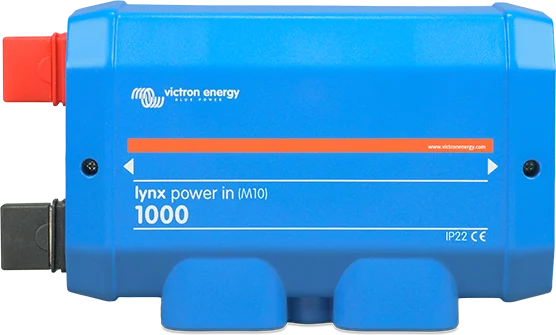
Lynx Power In 1000 — module linking the positive and negative busbars, without fuses
Lynx Power In and Lynx Class-T Power In
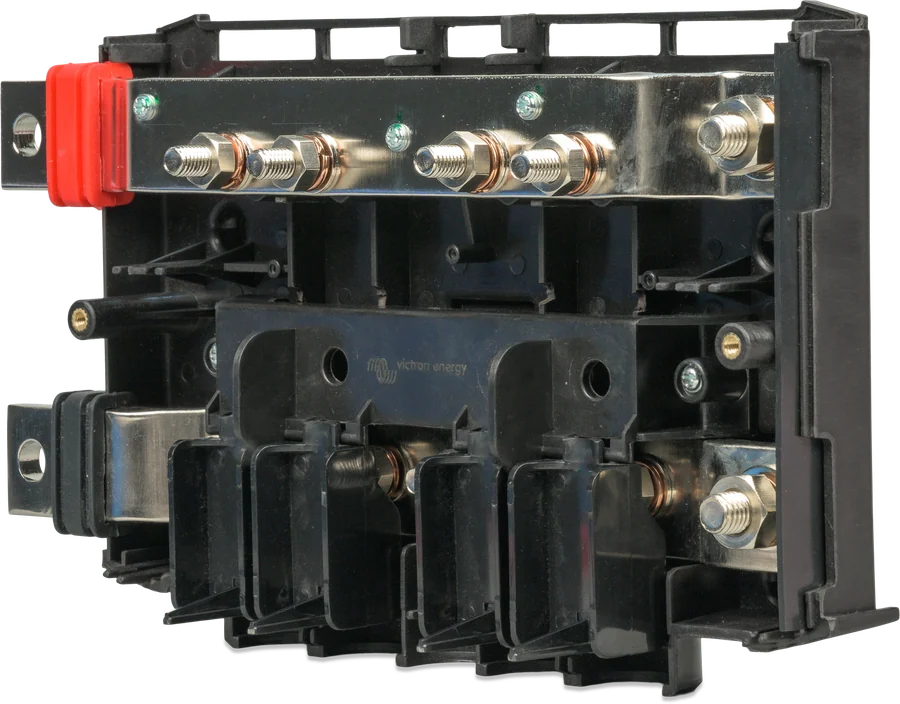
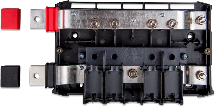
DC busbar modules for the Lynx distribution system. Lynx Power In has positive and negative busbars with four connections for batteries, loads or chargers. Lynx Class-T Power In connects and protects up to two lithium battery strings. Both: 1,000 A continuous DC, 9–60 V DC.
- 9–60 V DC
- 1,000 A DC continuous
- M8 or M10 busbar
- 2 Class-T fuse positions; fuses sold separately
Two DC input modules
The Lynx distribution system is a modular DC busbar system: connections, distribution, fuses, battery monitoring or lithium battery management. Connected modules create a continuous negative and positive busbar. You connect each module to others on the left and on the right.
You can use Lynx Power In and Class-T Power In and Lynx Distributor without Lynx Smart BMS when monitoring or BMS is not needed.
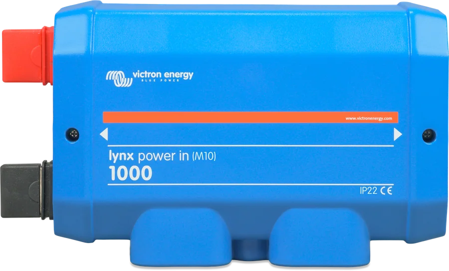
| Feature | Lynx Power In (M8 or M10) | Lynx Class-T Power In (M10) |
|---|---|---|
| Voltage range | 9–60 V DC | 9–60 V DC |
| Rated current | 1,000 A DC continuous | 1,000 A DC continuous; max. 800 A in one module (2 × 400 A) |
| Busbar between modules | M8 or M10 | M10 |
| Connections | 4 for batteries, loads or chargers and ground | 2 for batteries or DC equipment, two Class-T fuses and ground |
| Fuses | No positions — external protection | 2 Class-T positions. Standard black-marked 3/8" nuts, but some units have M10 bolts and nuts (the manual gives only a general serial-number pattern) — check which nuts your unit has |
| Cable lugs | always M8 | M10, up to 120 mm² or 3/8"–4/0 AWG |
| Ingress protection | IP22 | IP20 |
| Housing (h × w × d) | 290 × 170 × 80 mm | 279 × 169 × 97 mm |
| Weight | 2.1 kg | 2.1 kg |
| Material | ABS housing, 8 × 30 mm tinned copper busbar | ABS housing, 8 × 30 mm tinned copper busbar |
In Lynx Power In, the M10 designation refers to the inter-module connectors. The fuse and cable connections are always M8. Lynx Class-T Power In has only an M10 busbar and connects to the other Lynx M10 products.
Lynx Shunt VE.Can: check the connector version; the Lynx system documentation lists M8 and M10 versions. You cannot connect M10 modules directly to M8 modules, and vice versa.
Where Class-T Power In sits in the Lynx system
Simplified DC distribution with Lynx modules. Illustrative diagram — it shows the order of connections, not a complete design. Hover over or tap a diagram item to see the description.
- Batteries → Class-T Power InUp to two lithium strings on the left. M10 lugs.
- Class-T Power InTwo Class-T fuses. 1,000 A DC, 9–60 V; max. 800 A in one module.
- Lynx Smart BMSBatteries on the left, loads on the right. Bluetooth and VE.Can.
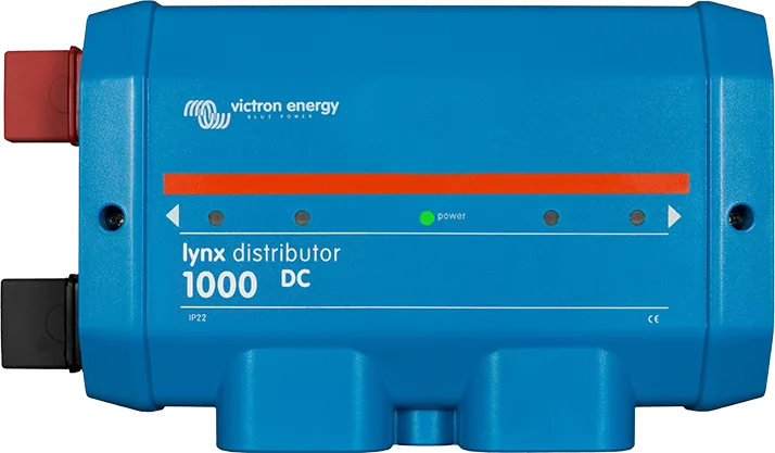
- Lynx DistributorContinuous DC busbar for loads and chargers.
- Loads and chargersOn the right-hand side of the Lynx system.
- Earthing and Cerbo GXSingle earth after the BMS. VE.Can to GX and VRM.
Current, voltage, environment
Lynx Distributor, Lynx Shunt VE.Can, Lynx Class-T Power In and Lynx Power In have a rated current of 1,000 A at a system voltage of 12 V, 24 V or 48 V. At 1,000 A, power is 12 kW at 12 V, 24 kW at 24 V and 48 kW at 48 V.
Lynx Smart BMS or the discontinued Lynx Ion may have a lower rated current. Lynx Smart BMS is available as a 500 A model with M8 or M10 busbars, or 1,000 A with M10 busbars. The total fuse value of all circuits must not exceed the rated current of the Lynx module with the lowest current rating in the system.
| Parameter | Value |
|---|---|
| Voltage range | 9–60 V DC |
| Rated current | 1,000 A DC continuous |
| Operating temperature | −40 °C to +60 °C |
| Storage temperature | data tables in both manuals: −40 °C to +60 °C; precautions: −40 °C to +65 °C |
| Humidity | max. 95% (non-condensing) |
| Ingress protection | Lynx Power In: IP22; Lynx Class-T Power In: IP20 |
| Lynx Power In dimensions | table: 290 × 170 × 80 mm; drawings LYN020102000 (M8) and LYN020102010 (M10) show, among other things, 288 mm (M8) and 285.1 mm (M10) |
| Lynx Class-T Power In dimensions | 279 × 169 × 97 mm |
| Weight | 2.1 kg |
Torques, sequence, fuses
Do not work on live busbars. Before removing the cover, disconnect all positive battery terminals. Only qualified people may work on batteries — follow the warnings in the battery manual.
- Disconnect the battery positive Before making positive connections, disconnect all positive cables from the battery to avoid short circuits. You power the Lynx system last, by connecting the battery positive terminal.
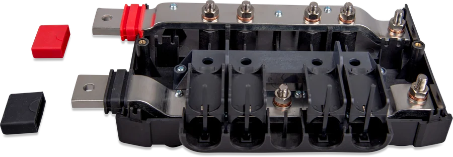
- Open the enclosure Undo the 2 cover screws. The contacts on the left are protected by a removable rubber sleeve. Store the product in a dry environment.
- Mount the assembly Mount the Lynx assembly in the installation position through the 5 mm mounting holes. You can mount the modules in any orientation. When mounting upside down, use the supplied stickers so the text is readable.
- Polarity and terminals The red busbar is positive, the black is negative. For Lynx Class-T Power In, all cables must have M10 lugs (for up to 120 mm² or 3/8"–4/0 AWG). For Lynx Power In, all cables must have M8 lugs. Remove the cable divider post if the cable diameter exceeds 10 mm.
- Earthing If the system requires earthing, there may be only one earthing connection in the system. Make it after the Lynx Smart BMS, Lynx Shunt VE.Can or the battery monitor shunt.
- Class-T fuses Lynx Class-T Power In has space for two Class-T fuses. Section 2.1 of the manual lists: 225 A, 250 A, 350 A and 400 A. Section 4.2.2 also adds 300 A. You buy them separately — Victron does not keep them in stock. Always use fuses with the correct voltage and rated current. Fit them with the black-marked 3/8" nuts, so you do not confuse them with the M10 DC busbar nuts (otherwise you will damage the thread). Some units have M10 bolts and nuts at the fuses, not marked black — the manual does not give an exact serial number range, so check the thread on your unit. Orientation matters because the flanges are not always flat. If the flanges do not sit flat on the busbar, rotate the fuse 180° along its longitudinal axis. In one Class-T Power In, the maximum current is 800 A (2 × 400 A). For three or more lithium battery strings, use multiple Class-T modules. Lynx Power In has no fuse positions — protection is external. If you connect batteries and loads directly to the inter-module terminals, additional fusing may be required.
- Torque Lynx Class-T Power In: washer, spring washer and nut on M10 bolts — 33 N·m. Lynx Power In M8: 14 N·m. Lynx Power In M10: M10 nuts 33 N·m (17 N·m for serial numbers before HQ2340…), M8 nuts 14 N·m. In the cable heating section, the Lynx Power In manual gives 14 N·m (17 N·m for the M10 model) — this is a different value from the M10 mounting torque. Do not exceed the maximum torque.
- Pre-energising check Check DC cable polarity, cross-section, correct crimping of lugs and tightening of connections. On Lynx Power In, gently pull each battery cable. In the example with two parallel lithium batteries on Class-T, the cables for each battery have identical length. Only then connect the battery positive.
Connecting modules
Lynx Shunt VE.Can: check the connector version; the Lynx system documentation lists M8 and M10 versions. You cannot connect M10 modules directly to M8 modules, or vice versa.
- You connect each Lynx module to other modules on the left and on the right. Together they form a continuous negative and positive busbar.
- When connecting on the right-hand side, remove the black plastic divider. Leave it in place in the outermost right-hand module.
- When connecting on the left-hand side, remove the red and black rubber sleeves. Leave them in place in the outermost left-hand module.
- Make sure the modules fit correctly into the rubber recesses of the connectors.
- When the system includes a Lynx Shunt VE.Can or a Lynx Smart BMS, you always connect batteries on the left-hand side, and loads and chargers on the right-hand side.
Lynx Distributor
Rated current 1,000 A at 12 V, 24 V or 48 V. Can be combined with Power In without Lynx Smart BMS.
Product pageLynx Smart BMS
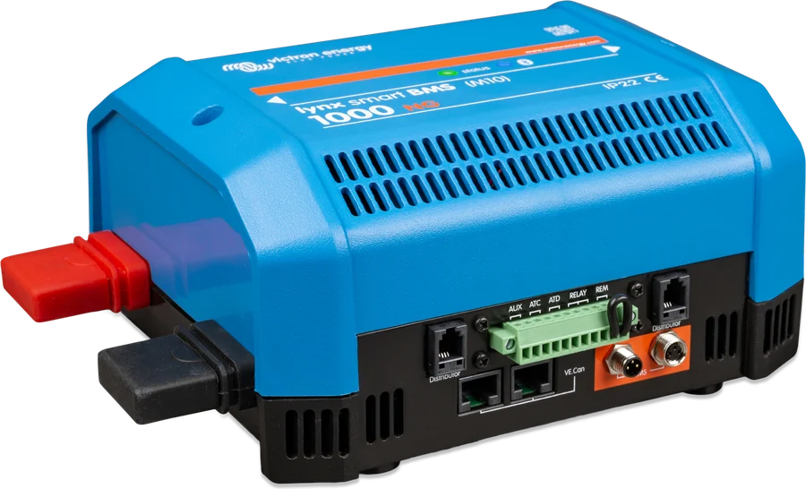
For Victron Energy Smart Lithium batteries. 500 A models (M8 or M10) and 1,000 A models (M10). Bluetooth and VE.Can.
Product pageLynx Shunt VE.Can
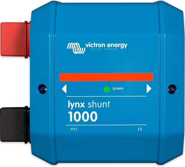
Check the connector version — the Lynx system documentation lists M8 and M10 versions. VE.Can to GX device.
Product pageFAQ
What is the difference between Lynx Power In and Lynx Class-T Power In?
Lynx Power In has four terminals for batteries, loads or chargers and no fuse positions. It is available in an M8 or M10 version, IP22 enclosure, dimensions in the table: 290 × 170 × 80 mm. Lynx Class-T Power In (M10 only) connects and protects up to two lithium battery strings: two terminals, two Class-T fuses, IP20, enclosure 279 × 169 × 97 mm. Both have a 1,000 A DC busbar, 9–60 V DC, mass 2.1 kg and an ABS enclosure.
Can you connect an M8 module to an M10 one?
Not directly. You cannot connect M10 modules directly to M8 modules, or vice versa. For Lynx Shunt VE.Can, check the connector version; the Lynx system documentation lists M8 and M10 versions.
Which fuses and where do you fit them?
Lynx Power In: external protection. Lynx Class-T: two Class-T fuses. Section 2.1 of the manual lists 225 A, 250 A, 350 A and 400 A; section 4.2.2 also adds 300 A. Victron does not keep them in stock. In one Class-T, the maximum current is 800 A (2 × 400 A). The total fuse value of all circuits must not exceed the rated current of the Lynx module with the lowest current rating in the system. For three or more lithium battery strings, use multiple Class-T modules.
Where do you connect the batteries and earthing?
If the system includes a Lynx Shunt VE.Can or Lynx Smart BMS, batteries are always on the left, loads and chargers on the right. If the system requires earthing, there is only one earthing connection — after the Lynx Smart BMS, Lynx Shunt VE.Can or the battery monitor shunt. The red busbar is positive, the black one is negative.
What tightening torque?
Class-T Power In (M10): 33 N·m. Power In M8: 14 N·m. Power In M10 during installation: M10 nuts 33 N·m (17 N·m before HQ2340…), M8 nuts 14 N·m. In the troubleshooting section for cable heating, the Power In manual gives 14 N·m (17 N·m for the M10 model) — a discrepancy with the installation chapter. Do not exceed the maximum torque.
What should you check when cables get hot?
Heating may be caused by a wiring or connection error. Check the torque (Class-T: 33 N·m on cables and fuses; Power In — values as above, with a discrepancy for M10), whether the conductor cross-section is sufficient for the current in the circuit, and whether the lugs are properly crimped. If the problem persists, report it to the dealer or installer from whom you bought the unit.
Manufacturer documentation
Content checked against Victron Energy documentation (datasheets and manuals) — as of 19 September 2026. Report a content error · Revision log