
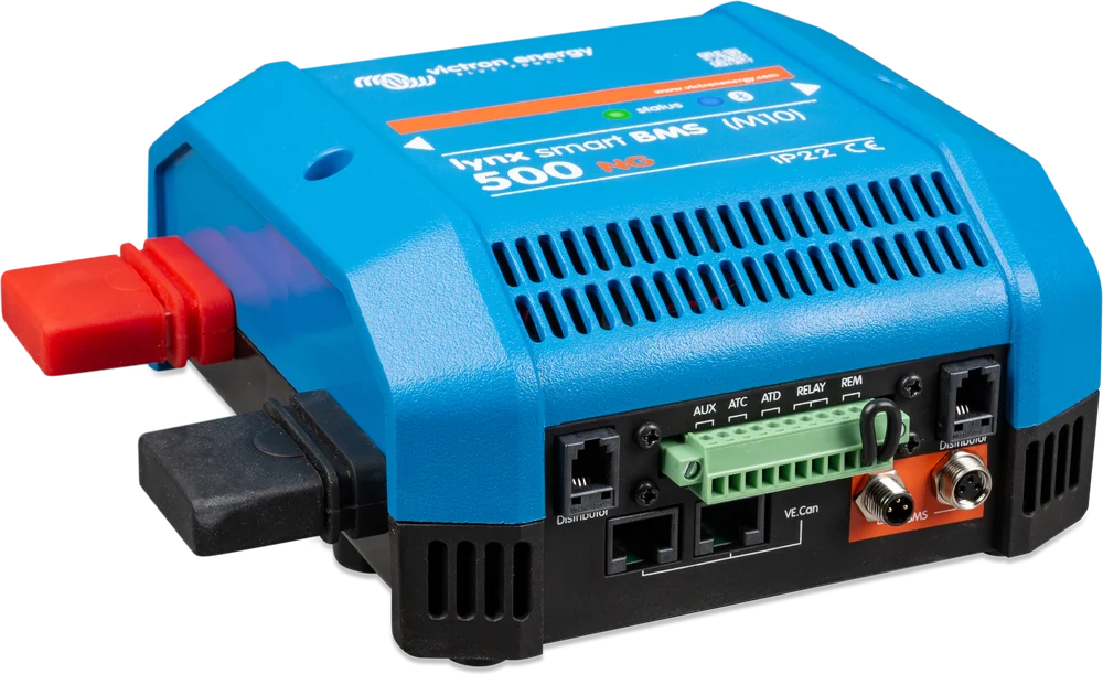
Lynx Smart BMS NG 500 A — front three-quarter view
Lynx Smart BMS and Lynx Smart BMS NG
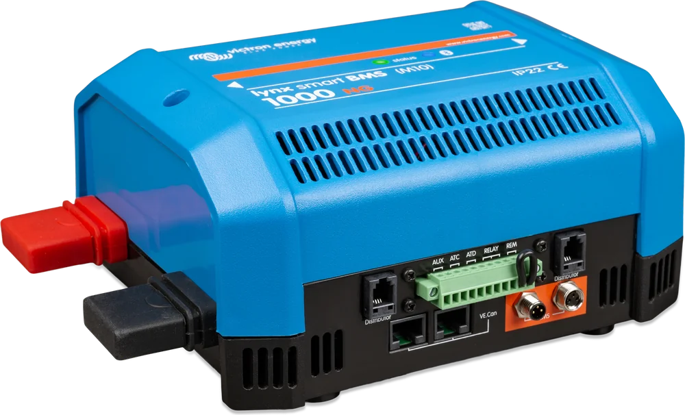
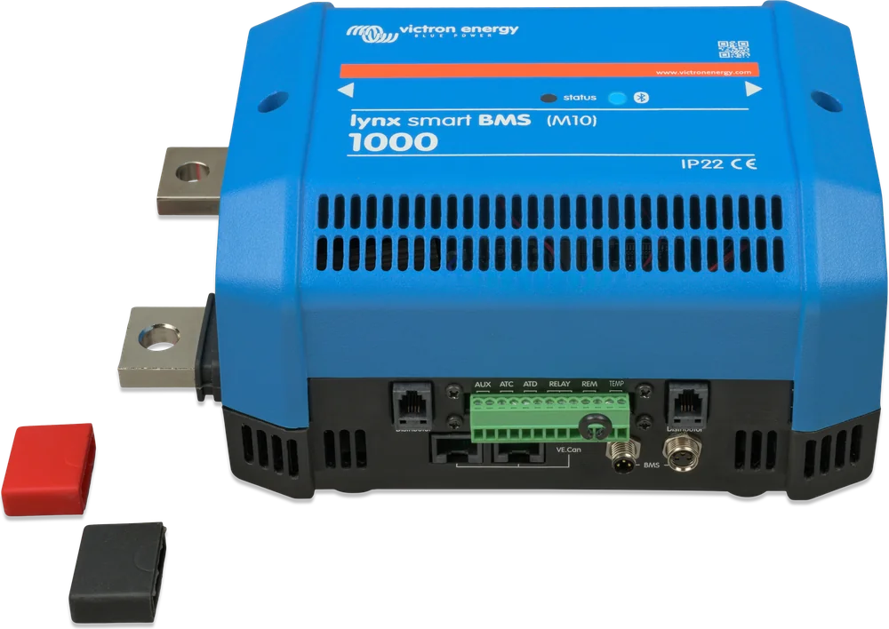
BMS, safety contactor and battery monitor in one Lynx system housing. It protects a Victron lithium battery bank on a yacht, in a campervan and in a home energy storage system. In an alarm, it first switches off chargers or loads with ATC/ATD signals and via DVCC, and the contactor disconnects the installation as an emergency measure.
- 12 / 24 / 48 V
- 500 or 1,000 A contactor
- M10 busbars
- Bluetooth
- VE.Can · NMEA 2000
Which version for which battery?
Lynx Smart BMS comes in two families that look almost the same from the outside. Each is designed for a different Victron battery series — match the BMS to the battery, not the other way round.
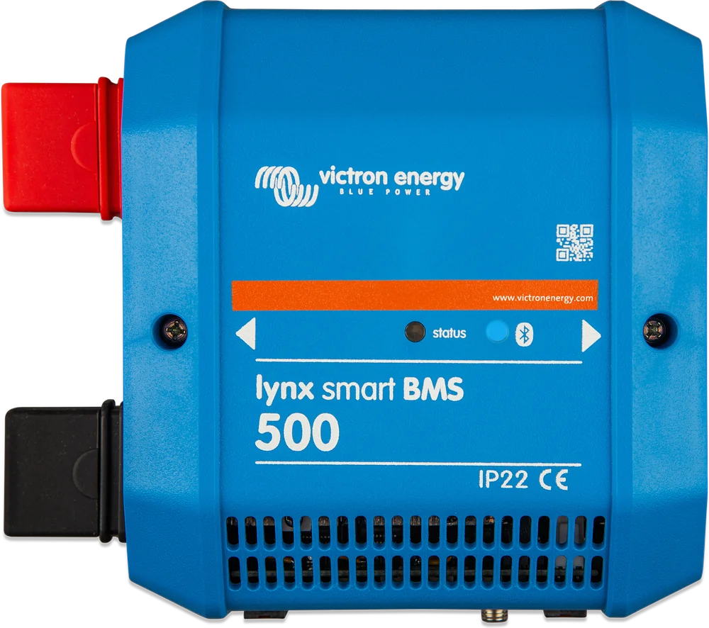
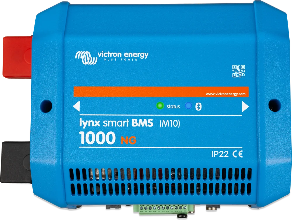
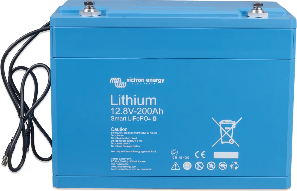
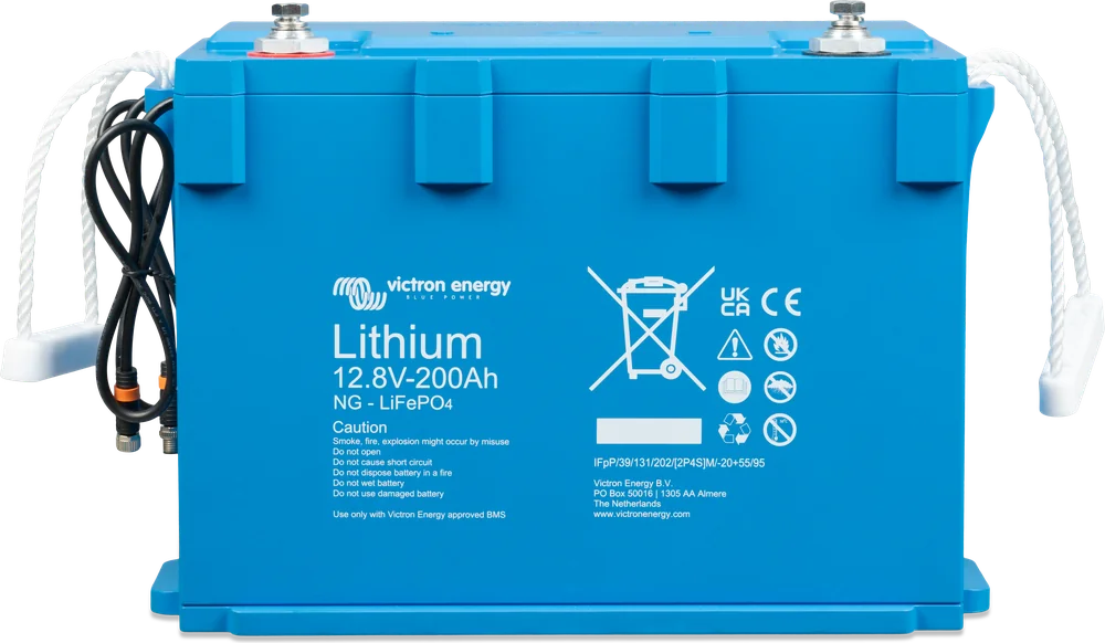
| Lynx Smart BMS | Lynx Smart BMS NG | |
|---|---|---|
| For batteries | Victron Lithium Smart (LiFePO4) 12.8 V and 25.6 V | Victron Lithium NG (LiFePO4) 12.8 V, 25.6 V and 51.2 V |
| System voltage | 12, 24 or 48 V | 12, 24 or 48 V |
| Max. number of batteries | 20 | 50 (12.8 and 25.6 V batteries) · 25 (51.2 V batteries) |
| Max. bank energy | 84 kWh (12 V) · 102 kWh (24 and 48 V) | 192 kWh (12.8 V batteries) · 384 kWh (25.6 V) · 128 kWh (51.2 V) |
| Contactor versions | 500 A i 1000 A | 500 A i 1000 A |
| Busbars | M10 (older 500 A version: M8) | M10 |
| Battery monitor | built-in | built in; NG batteries also have their own shunts |
Both BMS families and both battery series are blue and very similar. The name decides: if the battery has “NG” in the name, you need a BMS with the “NG” suffix. If it is a “Smart” battery without “NG” — you need the Lynx Smart BMS without the suffix.
Three devices in one housing
BMS. Victron lithium batteries measure cells and temperature themselves, but the BMS decides when to stop charging or disconnect loads. Lynx Smart BMS does this via the GX device (DVCC) and the “allow-to-charge” and “allow-to-discharge” contacts.
500 or 1000 A contactor. This is the second line of defence: if the primary control fails, the contactor disconnects the entire installation from the battery. It can also work as a remotely controlled main system switch.
Battery monitor. State of charge, voltage, current and history — on your phone and on the GX display. That is why a system with Lynx Smart BMS usually does not need a separate monitor such as SmartShunt.
- built-in pre-charge circuit — no current surge when connecting the inverter,
- the most advanced BMS in Victron’s range for a given battery series,
- part of the modular Lynx distribution system.
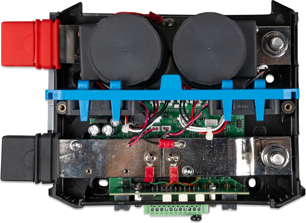

What Lynx Smart BMS can do
Safety contactor
500 or 1000 A continuous current. Disconnects the installation from the battery if the primary protection fails (ATC, ATD, DVCC). Also works as the main switch.
Pre-charge
When connecting an inverter with large capacitors, the pre-charge circuit limits the current surge. No separate pre-charge device is needed.
Battery monitor
State of charge, voltage, current, history and live status. After enabling Instant Readout (factory disabled), the key data is visible in the app without connecting to the BMS.
DVCC and ATC / ATD contacts
Compatible inverters/chargers and solar charge controllers are controlled automatically by the GX device and DVCC; in an NG system this also applies to the Orion XS 12/12-50A. Other devices with a remote on/off input can be controlled via the ATC and ATD contacts.
Relay and alternator mode
The relay works as an alarm (with pre-shutdown warning) or controls the alternator regulator. In Alternator mode, ATC first shuts down the alternator, and only after 2 s opens the contactor.
AUX output 1.1 A
Powers a selected device — for example the GX device — even when the BMS has disconnected the loads because of low cell voltage. If no charging voltage appears for 5 min after a disconnection due to low cell voltage (or after reaching the discharge threshold), the BMS enters OFF mode: contactor open, AUX and ATC/ATD disabled. A low-cell-voltage cut-out should be treated as a last resort; after such an event, recharge the battery immediately and disconnect residual loads, because even small loads can damage a deeply discharged battery. Exit OFF mode by applying charging voltage or switching the Remote or software switch off and on.
VE.Can and NMEA 2000
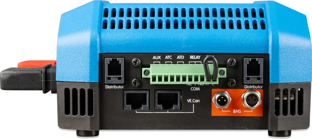
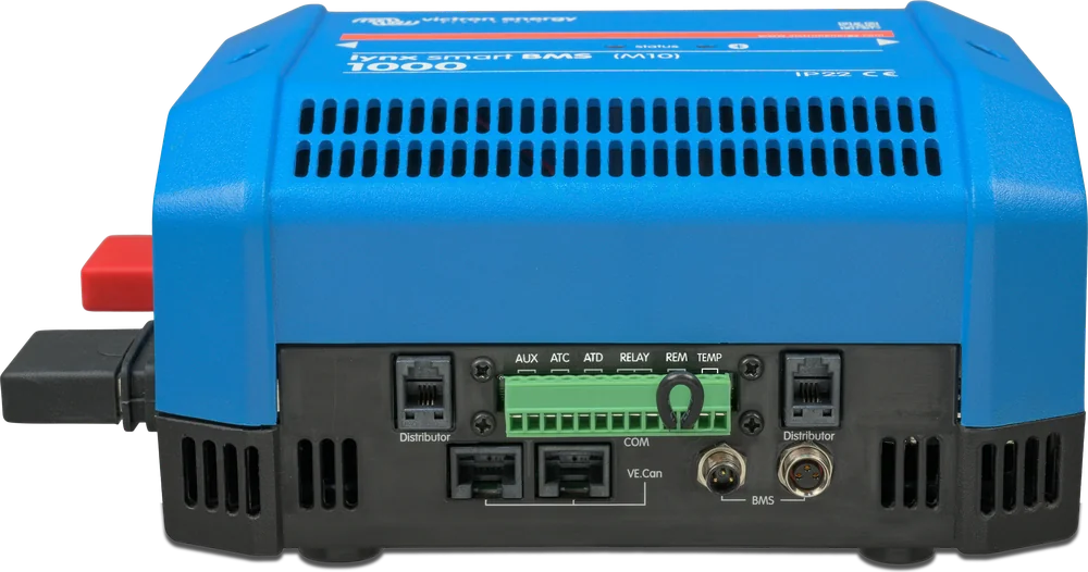
Using the supplied RJ45 cable to the GX device VE.Can port — not to BMS-Can; bus profile “VE.Can & Lynx Ion BMS (250 kbit/s)”, terminators at both ends of the network. On a yacht, the data goes to the multifunction display (VE.Can to NMEA 2000 micro-C cable required).
Fuse monitoring
Monitors up to 4 Lynx Distributor modules (from serial number HQ1909, with address A–D set by DIP switches) and their fuses. A blown fuse is reported in VictronConnect and on the GX display.
Parallel operation
Up to 5 BMS units in one installation, each with its own battery bank. Requirements: firmware of each BMS from v1.11, GX device from v3.40, BMS units with the same current rating (500 + 500 A or 1000 + 1000 A), equal load-side cable lengths to a common Lynx Distributor or busbar, and blocking diodes for each parallel AUX output. Together they form one redundant system — if one bank fails, the rest keeps working.
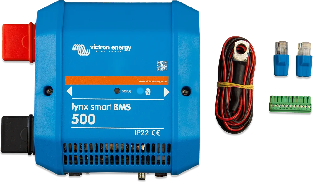
500 A or 1000 A — technical data
Both families (Smart and NG) have the same dimensions and the basic hardware parameters listed in the table. However, they work with different battery series, and battery-derived thresholds may differ — for example, the high cell voltage threshold is 3.75 V for Lithium Smart and 3.60 V for Lithium NG.
| Parameter | 500 A | 1000 A |
|---|---|---|
| Contactor — continuous current | 500 A | 1000 A |
| Contactor — peak current | 600 A for 5 min | 1,200 A for 5 min |
| Power consumption in ON mode (at 12 V) | approx. 2.6 W (217 mA) | approx. 4.2 W (350 mA) |
| Dimensions (H × W × D) | 190 × 180 × 80 mm | 230 × 180 × 100 mm |
| Weight | 1.9 kg | 2.7 kg |
| Busbars · tightening torque | M10 · 33 Nm | M10 · 33 Nm |
Power consumption in ON mode depends on the relay state. According to the Lynx Smart BMS datasheet (Smart series), the previous version of the 500 A model had M8 busbars. 1000 A units with a serial number before HQ2340 are tightened to 17 Nm.
- Battery voltage range
- 9–60 V DC
- Max input voltage
- 75 V DC
- Reverse polarity protection
- none
- Consumption: OFF / standby
- 0.3 mA / approx. 0.6 W (50 mA at 12 V)
- Pre-charge — min. load resistance
- 10 Ω (12 V) · 20 Ω (24 i 48 V)
- AUX output
- 1.1 A continuous, self-resetting fuse
- ATC and ATD contacts
- 0.5 A at 60 V DC
- Alarm relay (SPDT)
- 2 A at 60 V DC
- Connections
- VE.Can (RJ45), I/O terminal block, BTV (M8), RJ10
- Enclosure · protection rating
- ABS · IP22 (ingress protection)
- Operating temperature
- −40 … +60 °C
- Busbars
- tinned copper, 8 × 30 mm
Modules bolted together into one busbar
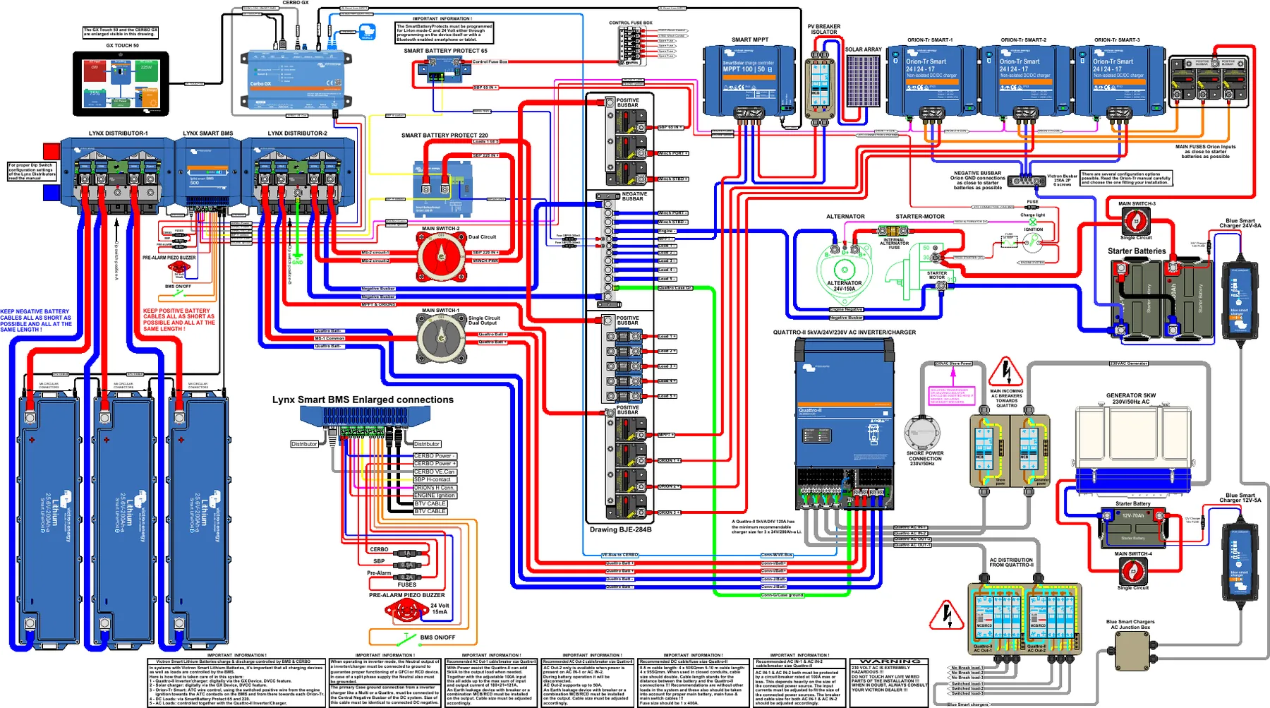
Lynx is a modular DC distribution system: the modules are linked side by side with busbars, without a tangle of cables. In the manufacturer’s example, the first Lynx Distributor connects two battery branches with fuses, Lynx Smart BMS works in the middle, and the second Distributor distributes protected outputs to the inverter, loads and chargers.
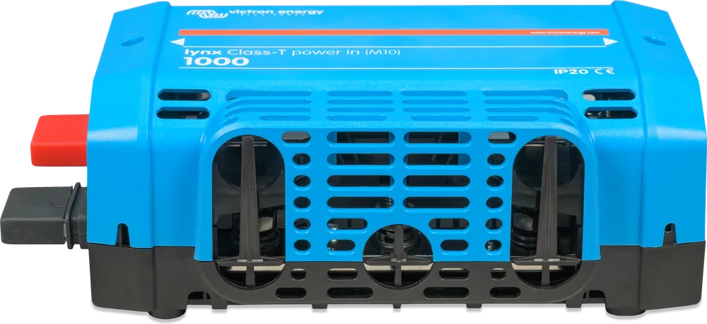
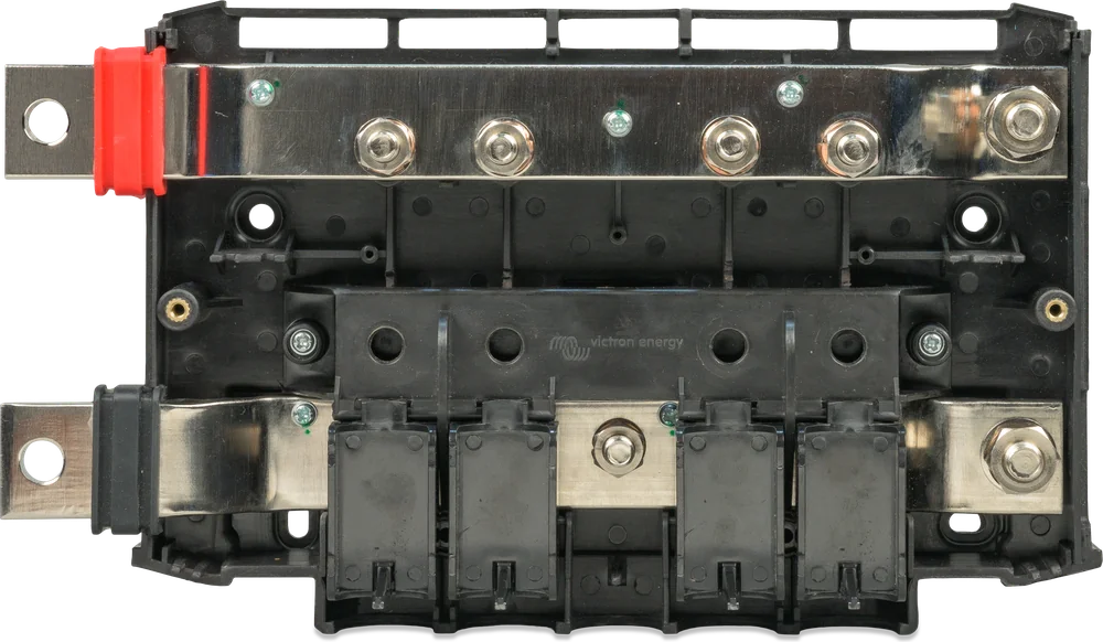
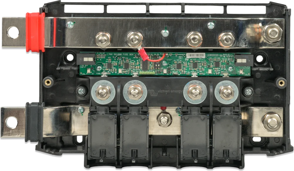
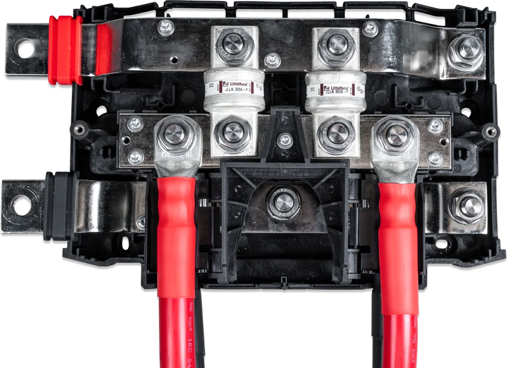
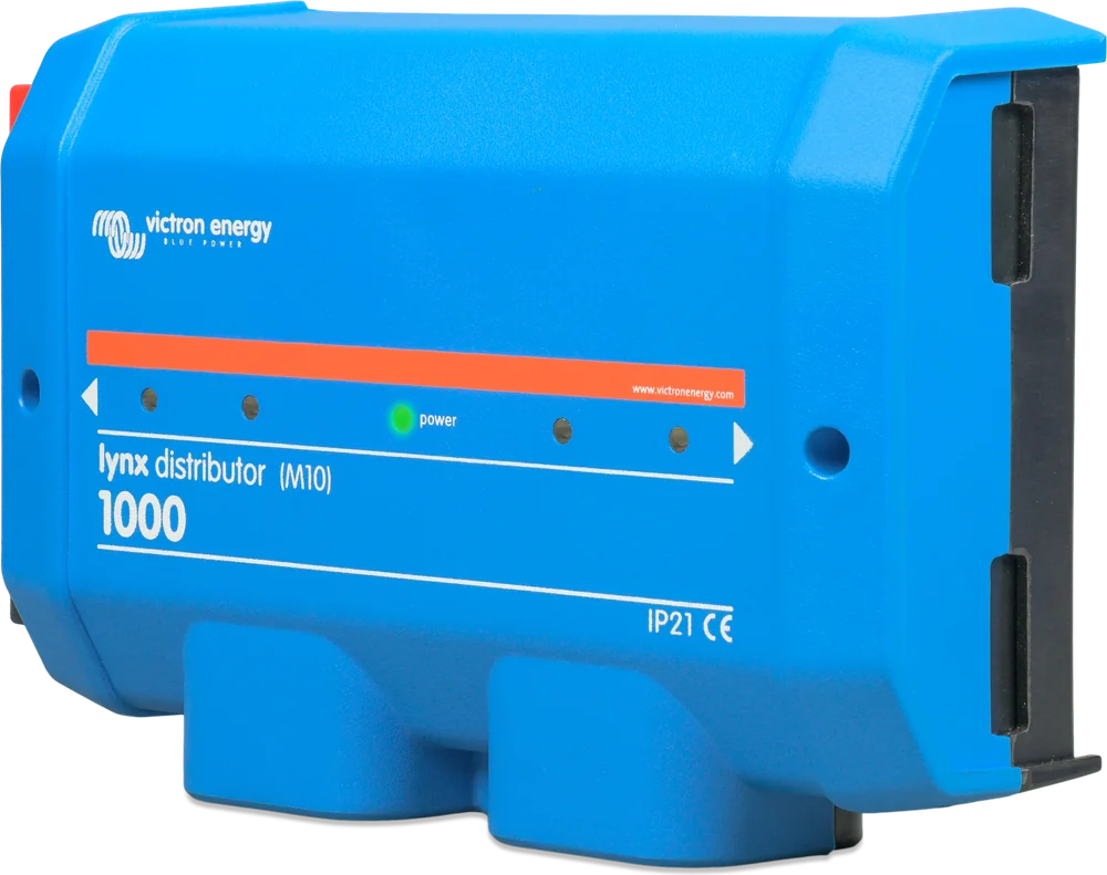
The manufacturer recommends several Lynx Class-T Power In modules in that case. The NG series and new modules have M10 busbars and connect with all Lynx M10 products.
Each Lynx Distributor includes an RJ10 cable to the BMS. After connection (up to 4 modules), a blown fuse will be shown in the app and on the GX display.
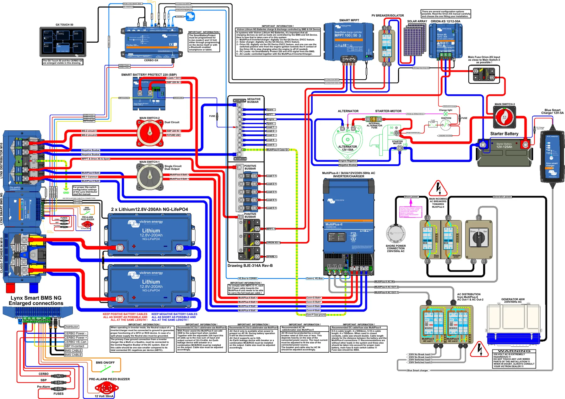
Lynx Smart BMS in the system
A simplified yacht or campervan system with inverter and panels. Hover over or tap a diagram element to see its description.
- Batteries → fusesThe Lynx module connects and protects the battery branches (e.g. Class-T Power In).
- Lynx Smart BMSAll current flows through its contactor and shunt; the BMS cables (M8) come from the batteries.
- Lynx Distributor → devicesMultiPlus-II, MPPT and DC loads, each through its own fuse.
- VE.Can → Cerbo GXThe GX uses DVCC to control the inverter and charge controllers according to the BMS.
- ATC / ATD → remote on/offFor devices that do not communicate with GX.
Full manufacturer schematics
What to watch out for
According to the datasheet, the BMS is not protected against reverse polarity. Before connecting the batteries, check the polarity of every wire.
In the normal orientation, the battery is on the left side of the Lynx Smart BMS, and the loads and chargers are on the right. When the modules are mounted upside down, the sides are visually reversed: the battery is on the right, and the loads and chargers are on the left. Reversed power distribution is a separate procedure: it requires swapping the sense wires and setting “Reversed”; before opening the enclosure, disconnect all voltage sources and use a voltmeter to make sure there is no residual voltage. The negatives of all loads and chargers must be on the system side of the shunt — otherwise the state of charge will be incorrect.
The Lynx Smart BMS only warns at excessive current. Fuses must be provided separately — for example, a Lynx Class-T Power In on the battery side and a Lynx Distributor on the loads side. Select the fuses for the maximum voltages and currents of the circuit concerned; the sum of the fuse ratings of all circuits should not exceed the rated current of the Lynx module or the weakest Lynx module in the system. The Lynx Power In has no fuses.
Tighten the busbars to 33 Nm (units before serial number HQ2340 — 17 Nm, discontinued M8 version — 14 Nm). A loose connection at hundreds of amps is a risk of overheating.
The AUX output (1.1 A) also works after the loads are disconnected at low cell voltage — this allows the Cerbo GX to keep showing what happened and send an alarm.
The ABS enclosure has an IP22 rating. Install it in a dry technical compartment, together with the other Lynx modules.
Settings, monitoring and firmware updates are available in the VictronConnect app. Remotely — via the GX device and the VRM portal.
Frequently asked questions about Lynx Smart BMS
I have Victron batteries. Which Lynx Smart BMS should I choose?
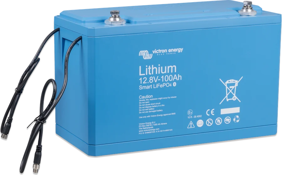
Check the battery name. The Victron Lithium Smart batteries (12.8 V and 25.6 V, with no “NG” in the name) use the Lynx Smart BMS. The Victron Lithium NG batteries (12.8 V, 25.6 V and 51.2 V) use the Lynx Smart BMS NG. Each version is intended for its own series — details in the table at the top of the page.
Do I need a SmartShunt with the Lynx Smart BMS?
Usually not. The Lynx Smart BMS has a built-in, full battery monitor: state of charge, voltage, current and history. The NG series batteries also have their own shunts and send this data to the BMS.
Why use a contactor if the BMS switches the chargers and loads off anyway?
Basic control (DVCC, ATC and ATD contacts) works through other devices. If one of them does not respond, the contactor is the second line of defence — it disconnects the whole installation from the battery. It also works well as a remotely controlled main switch.
Can I charge the batteries from the engine alternator?
Yes, but the BMS does not limit alternator current — it can only switch off an external alternator regulator. The manual recommends connecting the regulator to the ATC contact in new installations (the contactor still opens 2 s after ATC). The “Alternator ATC” relay mode is intended for older installations. To avoid overloading the alternator, use a DC-DC charger (for example, Orion XS) or an alternator/regulator matched to a lithium battery.
500 A or 1000 A?
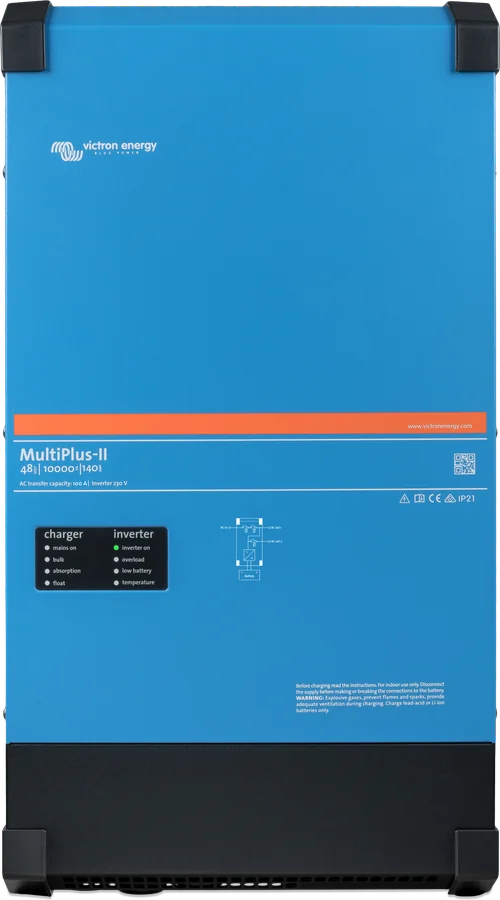
The key figure is the highest current that will flow from the battery — usually inverters draw it. Example (our calculation): a MultiPlus-II 12/5000 at full continuous power of 4,000 W draws about 350 A from a 12 V battery, which fits the 500 A version. With two such inverters, large inrush loads or a 12 V system with several large loads, it is safer to choose 1000 A. According to the manufacturer, the contactor can withstand 600 A (500 A version) or 1200 A (1000 A version) for 5 minutes.

Manufacturer documentation
- Lynx Smart BMS 500 A and 1000 A datasheetPDF · EN
- Lynx Smart BMS NG 500 A and 1000 A datasheetPDF · EN
- BMS overview for Lithium Smart batteriesPDF · EN
- BMS overview for Lithium NG batteriesPDF · EN
- Lynx Smart BMS product page (manual, schematics)victronenergy.com
- Lynx Smart BMS NG product page (manual, schematics)victronenergy.com
We prepared this description independently based on the manufacturer’s documentation. If there are any discrepancies, the current Victron Energy documentation is binding. You can report an error here.
Content checked against Victron Energy documentation (datasheets and manuals) — as of 19 September 2026. Report a content error · Revision log