
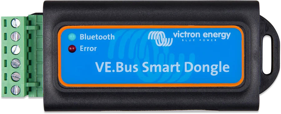
VE.Bus Smart Dongle — Bluetooth and Error LEDs and green terminal block
VE.Bus Smart dongle
A small device connected to the VE.Bus port of an inverter/charger (MultiPlus, Quattro) or VE.Bus inverter. It provides monitoring and basic control in the VictronConnect app via Bluetooth, and also measures battery voltage and temperature.
- Bluetooth
- VE.Bus (RJ45)
- 8–70 V DC
- voltage and temperature sensor
- VE.Smart
What you can do, and what you cannot
| Yes | No |
|---|---|
| switch on, switch off and “charger only” mode | configure the inverter/charger (for this you need MK3-USB and VEConfigure or VictronConnect) |
| AC input current limit (for example, for a campsite hook-up) | update the inverter/charger firmware |
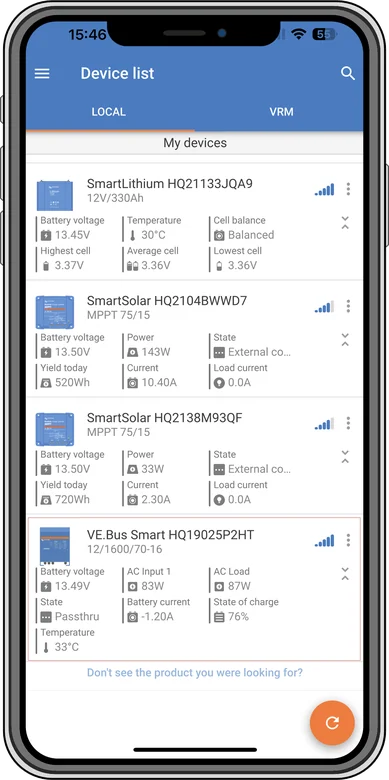
| view AC and DC parameters, status, warnings and alarms; Instant Readout in the device list | charger functions on an inverter without a charger (there is no AC monitoring, “charger only” mode or current limit) |
| battery voltage and temperature measurement — for the inverter/charger and for the VE.Smart network |
It works with a single unit and with parallel or three-phase systems. Temperature measurement lets you correct charging voltage according to battery temperature, and voltage measurement lets you compensate for voltage drop in the cables. Without an inverter, the dongle can work as a battery sensor in the VE.Smart network.
How to connect the VE.Bus Smart dongle
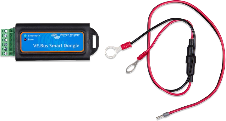
The dongle plugs into the VE.Bus port of the inverter/charger and connects to the battery with two wires. If it is to measure temperature, stick it to the battery case. Diagram only.
- Battery leadsRed (fused) to B+, black to B−; 10 mm ring terminals.
- Temperature measurementThe dongle stuck to the battery case measures its temperature.
- RJ45 cableTo the VE.Bus port of the inverter/charger; cable sold separately.
- UpdateDongle, inverter and app firmware — at least xxxx415, preferably xxxx419.
Connection
- Remove the terminal block. Red wire (with an in-line fuse) to the B+ terminal, black to B−.
- Black wire ring terminal to battery negative, red wire ring terminal to battery positive (10 mm ring terminals).
- If the dongle is to measure temperature, stick it to the top or side of the battery case; if not, mount it near the battery.
- Insert the terminal block and connect the dongle RJ45 socket to the inverter VE.Bus port with an RJ45 UTP cable (sold separately).
- Update the firmware of the dongle, the inverter/charger and the VictronConnect app. The inverter/charger must have firmware at least xxxx415, and for full functionality xxxx419 or newer.
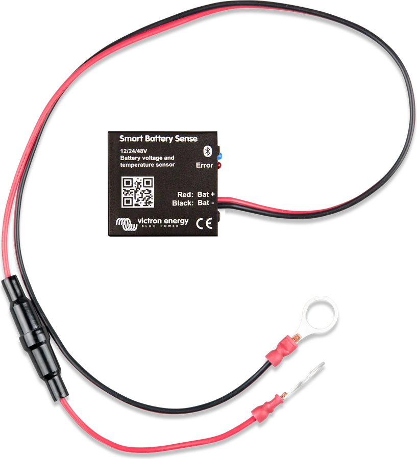
Instead of the built-in sensor, you can use an external temperature sensor for BMV-712/BMV-702 (sold separately; in this case you can ignore the “BMV702 only!” marking on the label). Then the sensor’s red wire goes to B+, the black wire to T−, and the dongle’s black power wire to B−. The black wire ring terminal goes to battery negative, and the sensor ring terminal to battery positive; the red wire from the kit is not used. The CD and Relay terminals have no function.
When the system includes GX, DMC or BMS
- The GX device has priority — because of VE.Bus limitations, only one device at a time can read inverter data. With GX connected, VictronConnect via the dongle shows only battery temperature and voltage and the status of the inverter/charger; AC-side voltage, current and power readings are unavailable. The dongle detects GX automatically (it listens for 30 s after startup).
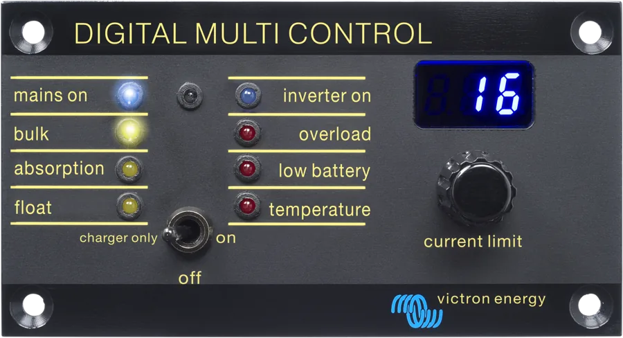
- The Digital Multi Control panel takes over from the dongle the on/off control, “charger only” mode, and current limit; the dongle can then only monitor parameters and act as a voltage and temperature sensor.
- VE.Bus BMS: the dongle then does not switch the inverter/charger to On, Off or “Charger only” — the VE.Bus BMS does that. For full functionality, use VE.Bus BMS V2.
- CAN-bus battery with GX: battery data overrides the dongle’s measurements.
- The dongle draws about 9 mA from the battery (12 V, in a VE.Smart network) — worth remembering during long periods of storage.
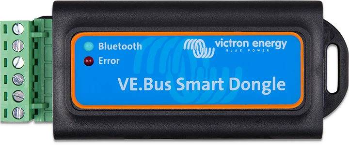
Blue and red
| Blue | Red | Meaning |
|---|---|---|
| flashing slowly | off | working, waiting for Bluetooth connection |
| on | off | connected to VictronConnect |
| off | off | not working — usually no power: check the fuse and battery cables |
| flash rapidly alternately | firmware update (not connected) | |
| on | on | hardware fault — dongle not visible in the app, not transmitting data |
Most common problems
- Only the battery page is visible, no inverter — the dongle is not communicating with the inverter: switch the inverter on, check the RJ45 UTP cable. Sometimes you need to refresh the device list.
- AC current limit cannot be changed — update the inverter/charger firmware to xxxx419 or later.
- Voltage too low with an external sensor — usually the B− wire is not connected to the battery negative; the inverter may then overcharge the battery.
- Voltage higher by about 0.6 V (12 V), 1.2 V (24 V) or 2.4 V (48 V) — according to the manual this means the dongle is faulty; undercharging may occur.
Frequently asked questions about the VE.Bus Smart dongle
What does the dongle show in the app?
View and basic control of the inverter/charger via Bluetooth, plus battery voltage and temperature. Full inverter configuration still requires configuration software.
How do you connect the wires?
Red wire (with in-line fuse) to the B+ terminal, black to B−; fit the 10 mm eyelets to the battery terminals. Connect the dongle’s RJ45 socket to the inverter’s VE.Bus port with an RJ45 UTP cable bought separately.
Does the dongle measure battery temperature?
Yes, if you stick it to the top or side of the battery case. You can also use an external temperature sensor for BMV-712/BMV-702 — then the red sensor wire goes to B+, the black to T−, and the dongle’s black supply wire to B−.
What firmware must the inverter have?
At least xxxx415, and for full functionality xxxx419 or later. Also update the dongle itself and the VictronConnect app.
What are the CD and Relay terminals for?
For nothing — they have no function in this device.

Content checked against Victron Energy documentation (datasheets and manuals) — as of 19 September 2026. Report a content error · Revision log