
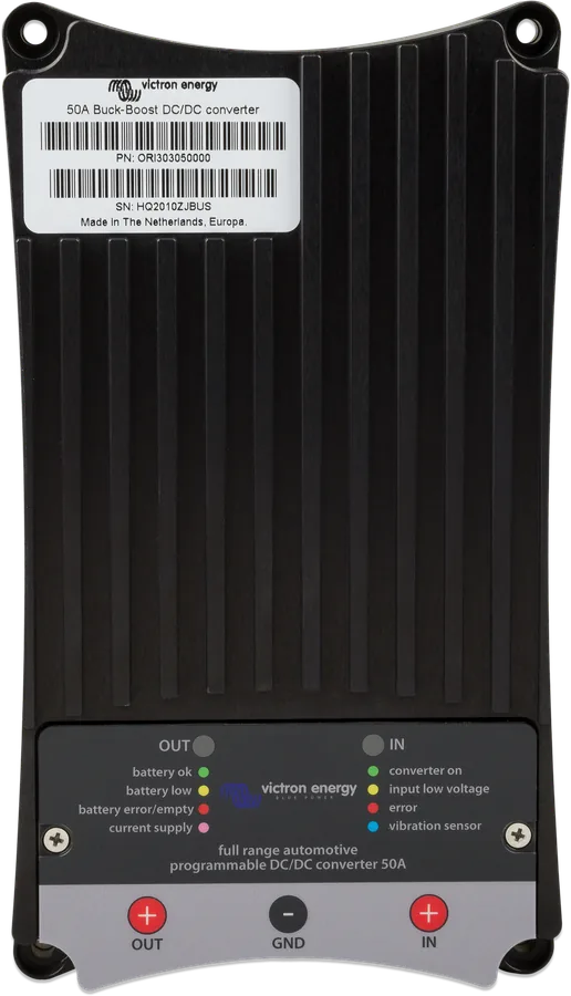
50 A Buck-Boost DC-DC from above — black heatsink, OUT and IN LEDs, M8 OUT, GND, IN terminals
Buck-Boost DC-DC 25 A, 50 A, 100 A
Converters for charging a 12 V or 24 V house battery from the alternator — including the intelligent alternator in Euro 5 and 6 engines, which gives too low or too high a voltage (for example, 15.4 V in a Mercedes). The output voltage does not depend on the input voltage (buck-boost), and the built-in engine-running detection protects the starter battery. They also protect the alternator from overload when charging lithium batteries. Settings are changed with the TSConfig program on a Windows computer.
- input and output 10–30 V
- 25 / 50 / 100 A (12 V)
- 12→12, 24→24, 12→24 V
- engine running detection
- USB, CAN (50 and 100 A)
Full charging from an alternator that “saves”
In a newer vehicle, the alternator is controlled by the engine electronics: it often lowers the voltage when the starter battery is charged, and raises it during braking (energy recovery). A house battery connected directly will not charge properly then, or will receive too high a voltage. Buck-Boost charges it at the set voltage regardless of whether the input is lower or higher — and it will never exceed the set current.
With lithium batteries, it limits the current drawn from the alternator: a lithium battery has very low resistance and, without limiting, could overheat the alternator.
- engine-running detection without interfering with the vehicle wiring or using a sensor — or switching on via pin 1 input (for example D+),
- one model for 12→12, 24→24 and 12→24 V (set in the software),
- limiting of output and input current and automatic reduction at high temperature,
- two control outputs (pin 1, pin 2) for switching loads on and off, optional battery temperature sensor.
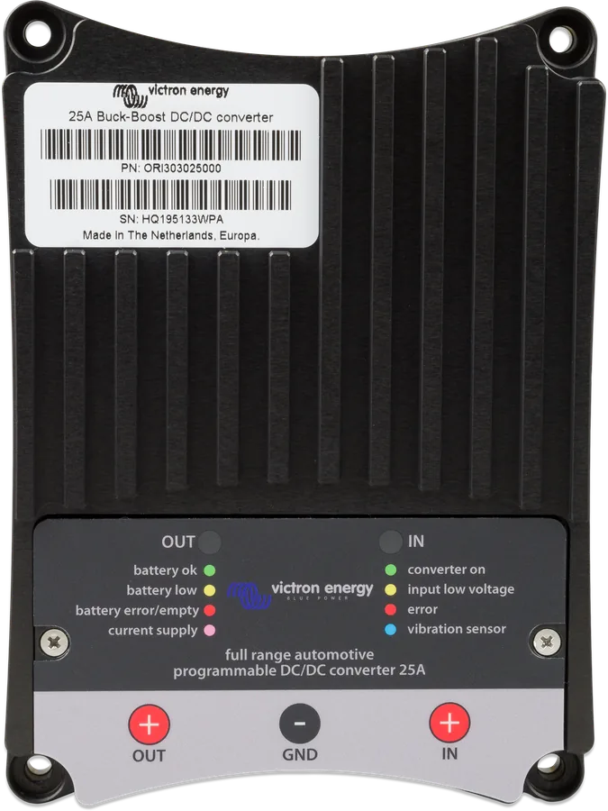
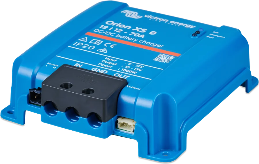
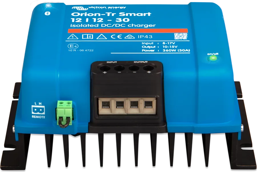
Buck-Boost is configured only with the TSConfig program (Windows) over USB — you need a USB A–B cable. The program also has a live monitoring window. If you prefer an app on your phone, you can choose Orion XS (50 or 70 A) or Orion-Tr Smart (up to 30 A).
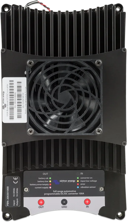
25 A, 50 A or 100 A
| Max. charging current | 12 V → 12 V | 24 V → 24 V | 12 V → 24 V |
|---|---|---|---|
| Buck-Boost 25 A | 25 A | 15 A | 10 A |
| Buck-Boost 50 A | 50 A | 25 A | 20 A |
| Buck-Boost 100 A | 100 A | 50 A | 50 A |
Common: input and output 10–30 V, low-voltage threshold 10 V, 7 mA draw when switched off (LEDs in power-saving mode), pin 1 input: on above 2 V, max. 30 V; pin 1 and pin 2 outputs supply the input voltage; −25…+60 °C. Output current is limited to the lowest of three values: the set charging current, the set input current and the temperature limit.
Starter battery → Buck-Boost → house battery
Connect all GND cables before the positive cables. Fuses on the input and output according to the table below. Indicative diagram.
- GND firstConnect the inverter’s ground, both batteries and the chassis before the positive cables.
- INFrom the starter battery through the input fuse.
- OUTTo the house battery through the output fuse.
- Pin 1 (optional)D+ or ignition instead of automatic engine-running detection.
- TSConfigOutput voltage, current and voltage threshold — before the first drive.
Values from the manual
| Model | 12 V — input and output fuse | 24 V — input and output fuse | Cross-section (cable up to 5 m) |
|---|---|---|---|
| 25 A | 40 A | 30 A | 16 mm² |
| 50 A | 60 A | 40 A | 35 mm² |
| 100 A | 125 A | 80 A | 50 mm² |
Connect all GND cables first (inverter, batteries, chassis), then the positive cables. Pay particular attention to the central M8 terminal (GND). The 50 A and 100 A models require an alternator that can supply a correspondingly high current to the inverter input.
If you use pin 1 or 2, fit the supplied resistors on older units; on newer units (with a finned enclosure) this is not needed.
Basic settings in TSConfig
Before first use, set in TSConfig (Windows, via USB; current versions are on the Victron software page):
| Setting | 12 V → 12 V | 24 V → 24 V | 12 V → 24 V |
|---|---|---|---|
| 20 — output voltage | 14.4 V | 28.8 V | 28.8 V |
| 22 — max. output current | no more than 60% of the vehicle alternator current | ||
| 24 — low voltage threshold | 11.8–12.2 V | 23.8–24.2 V | 11.8–12.2 V |
Do not set the low voltage threshold (setting 24) too low — the manual reserves any change for a qualified electrician. The inverter switches on when it detects engine running (or pin 1 is above 2 V), the input voltage is above the threshold, and the set delay time has elapsed. Set the charging voltage to suit the battery — for LiFePO4, follow the battery manufacturer’s recommendations.
What the IN and OUT LEDs indicate
IN green
Inverter on — detected by engine-running detection or voltage on pin 1.
IN yellow
Input voltage below the set threshold — the inverter will not switch on.
IN red
Internal temperature above the safety threshold (datasheet: inverter off).
IN blue
Short flashes: engine running detected, the inverter will start after the delay. Slow flashing: off and locked out because the input voltage is too low.
OUT green / yellow / red
The inverter is off and the house battery has: correct voltage / too low voltage / is discharged or not connected.
OUT purple
The inverter is operating and supplying the battery or loads. Purple flashing: off because at start-up the second battery voltage was too low (protection 31).
Documentation discrepancies: the manual (introduction) states 12.5 / 25 / 50 A for 24 V, while the datasheet and the manual’s technical data state 15 / 25 / 50 A; max. pin output current: 1 A (datasheet) and 1.5 A (manual); full current: up to 60 °C (datasheet) and full power at 40 °C (manual); IN red LED: “inverter on” (manual) and “off” (datasheet).
Most common questions about Buck-Boost
Do I need a D+ wire or an engine-running sensor?
No. The inverter detects engine running automatically and switches on after the set delay. If you prefer, you can switch it with a signal on pin 1 (purple wire, above 2 V), for example from D+ or the ignition.
How do I set the current so I do not overload the alternator?
The manual recommends setting the maximum output current to no more than 60% of the vehicle alternator current (setting 22 in TSConfig). The 50 A and 100 A models require an alternator with correspondingly high capacity.
Can I charge a 24 V battery from a 12 V system?
Yes — the 12 V → 24 V mode is set in the software. The current is then lower: 10 A (25 A model), 20 A (50 A) or 50 A (100 A).
Can I connect it to Cerbo GX or VictronConnect?
The Buck-Boost documentation does not describe a connection to GX or VictronConnect. Configuration and monitoring are via USB in TSConfig. The CAN connector (50 A and 100 A models) is used according to the manual for a CAN-bus temperature sensor.
Buck-Boost, Orion XS or Orion-Tr Smart?
Buck-Boost delivers the highest current (up to 100 A) and supports 12→24 V, but it is configured from a computer. Orion XS (50 or 70 A) and Orion-Tr Smart (up to 30 A, different voltages) have Bluetooth and the VictronConnect app.
Content checked against Victron Energy documentation (datasheets and manuals) — status as of 23 September 2026. Report an error in the content · Correction log