
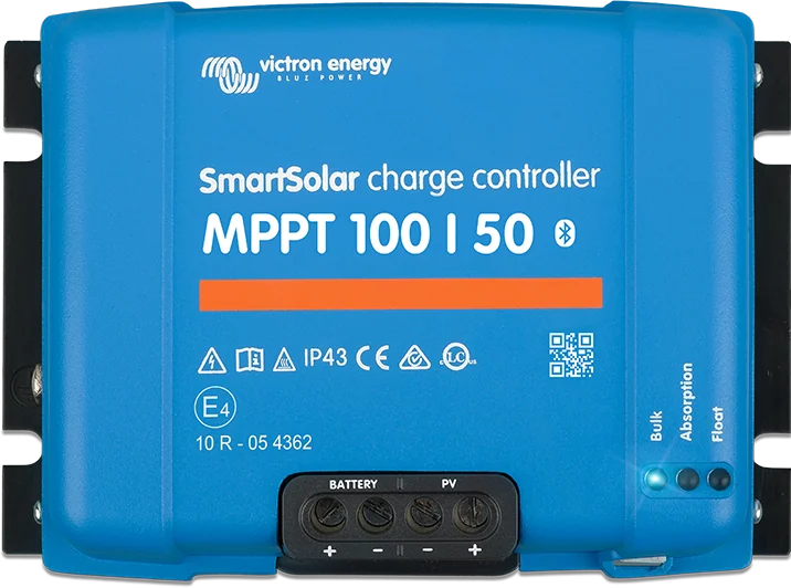
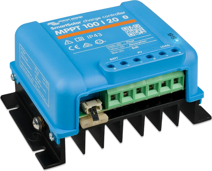
SmartSolar MPPT 100|50 — top view, BATTERY and PV terminals and Bulk, Absorption and Float LEDs
SmartSolar MPPT 100/30 and 100/50
Victron medium-power solar charge controllers: up to 100 V from panels and 30 or 50 A charging current for 12 or 24 V batteries. They sit between the small 75/10–100/20 models and the 150/250 V series — with a 12 V battery they correspond to about 440 and 700 W of PV.
- 100 V from panels
- 30 or 50 A
- 12/24 V (automatic)
- Bluetooth
- VE.Direct
More energy from the same panels
The MPPT solar charge controller constantly searches for the point at which the panels deliver the most power, and only then charges the battery. This means it extracts more from the array than a simple PWM controller — especially in cloud, at low temperatures, and when panel voltage is clearly higher than battery voltage.
The 100/30 and 100/50 models are the middle of the range: they accept panels up to 100 V and charge a 12 or 24 V battery at 30 or 50 A. They detect system voltage automatically at first start-up, and everything is set up in the phone over Bluetooth.
- with a 12 V battery, they correspond to about 440 W (100/30) and 700 W (100/50),
- efficiency up to 98% and self-consumption 20–30 mA,
- Bluetooth and VE.Direct port — view on your phone or in the GX device and VRM portal.
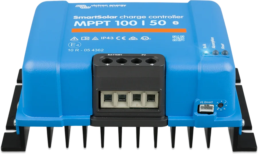

What the SmartSolar MPPT 100/30 and 100/50 can do
Maximum power point tracking
Charging starts when panel voltage exceeds battery voltage by 5 V, and continues as long as it is at least 1 V higher. Efficiency reaches 98%.
Bluetooth and VictronConnect
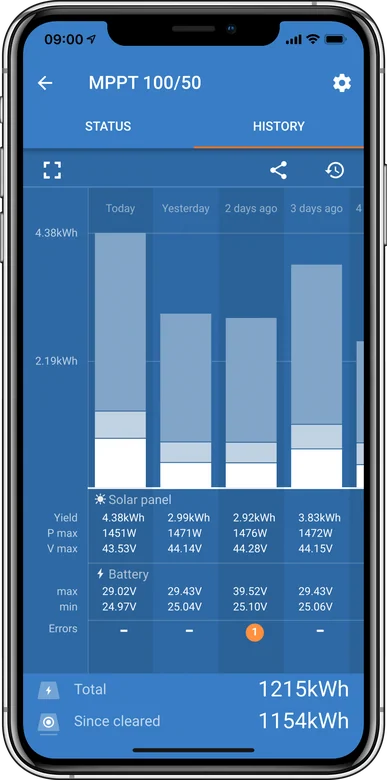
Operating state, voltages and currents on both sides, and yield history straight to your phone. Expert mode, which gives access to all parameters, is disabled by default.
Selector knob with eight algorithms
You can choose the charging profile without a phone — after changing position, the LEDs flash the selected position code for 4 seconds. The factory setting is position 2: absorption 14.4 / 28.8 V and float 13.8 / 27.6 V.
Profile for lithium batteries
For LiFePO4, select the lithium profile; for Victron Lithium Smart batteries, the battery manual specifies absorption 14.2 V for 2 hours and float 13.5 V. Equalisation is disabled.
VE.Smart network
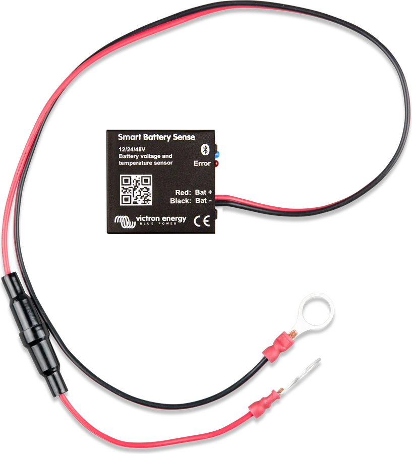
The controller can use battery voltage and temperature from Smart Battery Sense or from the SmartShunt, and synchronise charging with other SmartSolar controllers.
VE.Direct with RX and TX ports
By default, the RX port acts as remote on/off control (e.g. from a BMS), and TX as communication. Using a VE.Direct TX cable, you can create a “virtual” load output — these models do not have a physical one.
Temperature compensation
−16 mV/°C at 12 V and −32 mV/°C at 24 V. Operating range from −30 to +60 °C, full current up to 40 °C — that is why the controller is mounted close to the battery, but not above it.
Protections
PV input protection against reverse polarity (charging current then drops to zero and the unit heats up), protection against overheating and panel overvoltage. The electronics are IP43, and the terminals IP22.
Model comparison
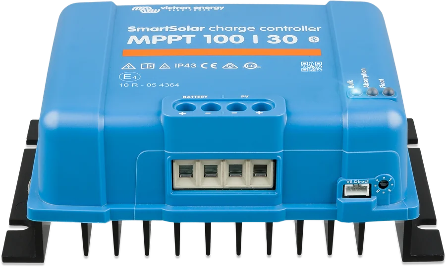
| Parameter | MPPT 100/30 | MPPT 100/50 |
|---|---|---|
| Charge current | 30 A | 50 A |
| Nominal panel power 12 V / 24 V | 440 / 880 W | 700 / 1400 W |
| Max. panel voltage (Voc) | 100 V | |
| Max. panel short-circuit current | 35 A | 60 A |
| Battery voltage | 12 / 24 V, automatically detected | |
| Self-consumption | 30 mA (12 V), 20 mA (24 V) | |
| Factory voltages (knob position 2) | absorption 14.4 / 28.8 V, float 13.8 / 27.6 V | |
| Temperature compensation | −16 mV/°C (12 V), −32 mV/°C (24 V) | |
| Operating temperature | −30…+60 °C, full current up to 40 °C | |
| Terminals, ingress protection | 16 mm² (AWG6); IP43 electronics, IP22 terminals | |
| Weight, dimensions (h × w × d) | 1.3 kg; 130 × 186 × 70 mm | |
You can connect panels with power higher than nominal — the controller will limit the input power. Charging starts when panel voltage exceeds battery voltage by 5 V, and continues as long as panel voltage is at least 1 V higher.
When to choose 100/30, and when 100/50
SmartSolar 100/30
Up to about 440 W of panels with a 12 V battery and 880 W with 24 V. Battery fuse 35–40 A, permissible array short-circuit current 35 A.
30 A · 100 VSmartSolar 100/50
Up to about 700 W at 12 V and 1400 W at 24 V. Fuse 55–70 A, short-circuit current up to 60 A. Same enclosure as the 100/30.
50 A · 100 VSmartSolar 150 V and 250 V
When panels connected in series exceed 100 V in frost, or the array is to be larger — you need a controller with a higher input voltage. SmartSolar 150/250 datasheet.
150–250 VWith a 12 V battery, the 100/30 will use about 440 W of panels, and the 100/50 about 700 W. Two 400 W panels at 12 V is 114% of the 100/50’s nominal power — at peak, the controller will limit input power (full calculation in MPPT sizing). For the 100/30 it would be 182% — above the 130% threshold, beyond which Victron’s official calculator considers the array oversized.
Voltage in frost: Panel open-circuit voltage (Voc) rises when temperature drops below 25 °C — by the percentage per degree given by the Voc temperature coefficient in the panel datasheet. For Victron BlueSolar panels (−0.35%/°C), at −20 °C this is about 16% more than in the catalogue. Victron recommends leaving at least 10% voltage headroom, and in a cold climate calculating Voc for the lowest expected temperature. Two panels with Voc 37 V in series give about 86 V at −20 °C — they fit within 100 V; three do not. For longer strings, choose SmartSolar 150 V or 250 V.
How to connect the SmartSolar MPPT 100/30 and 100/50
The sequence matters: battery first, after 10 s check the system voltage, then panels. The controller recognises battery voltage only at first start-up. Schematic diagram.
- Battery firstConnect the battery, wait 10 s and check the detected system voltage.
- Then panelsVoc with frost margin below 100 V; do not use panels with optimisers.
- Fuse35–40 A for 100/30, 55–70 A for 100/50, as close to the battery as possible.
- InstallationVertically, terminals down, up to 3 m from the battery, but not above it.
- MonitoringBluetooth in VictronConnect, VE.Direct to the GX device.
Fuses, sequence, torques
| Model | Battery fuse min. | max. | Tightening torque |
|---|---|---|---|
| 100/30 | 35 A | 40 A | 1.6 Nm (battery and PV) |
| 100/50 | 55 A | 70 A |
- Sequence: battery first, wait 10 s for voltage detection, then panels. The controller recognises battery voltage only at first start-up — after that it can be changed manually.
- Polarity check before connecting the battery and panels. Reverse battery connection can damage the controller and is not covered by the warranty. When installed according to the specification, the PV input is protected against reverse polarity — charging current then goes to zero and the unit heats up. However, an array with a short-circuit current above the permitted limit can damage the controller.
- Vertical installation on a non-flammable surface, terminals down, at least 10 cm of free space above and below the unit; within 3 m of the battery, but not directly above it. The temperature difference between the controller and the battery should not exceed 5 °C.
- Flexible, multi-strand copper conductors (single wire diameter up to 0.4 mm). According to the manual, a voltage drop on the battery cables above 2.5% is not acceptable.
- The PV input is not isolated from the battery circuit, so the PV, battery and control circuits are regarded as hazardous — they must not be accessible to the user (install only where unauthorised persons cannot reach them). Do not earth the positive or negative of the panel array; use one system earth point at the battery. Do not use panels with optimisers.
- Cover the panels during installation. The controller must not be used as a DC-DC converter or as a power supply without a battery.
Knob, profiles and load output
- The knob selects one of eight preset algorithms; after changing position, the LEDs flash for 4 s with the position code. Position 2 is the factory default. You can also set the parameters in VictronConnect (Expert mode is disabled by default).
- LiFePO4 battery: choose the lithium profile. For Victron Lithium Smart, the battery manual specifies absorption at 14.2 V for 2 h and float at 13.5 V (12.8 V). Equalisation is disabled by default and must remain disabled for lithium batteries.
- No physical load output — on these models you can create a “virtual” output via the VE.Direct port (VE.Direct TX cable), for example to control a Smart BatteryProtect. The factory default mode for this output is BatteryLife.
- RX port works by default as remote on/off (for example control from a BMS), TX as standard communication.
- VE.Smart: the controller can use battery voltage and temperature from Smart Battery Sense, and voltage, current (and temperature with the optional sensor) from SmartShunt or BMV-712, and synchronise charging with other SmartSolar units.
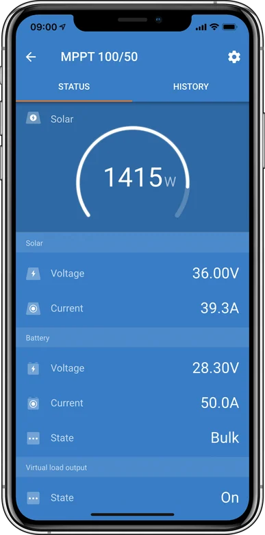
Most common signals
The full list of codes is in the charger and MPPT error codes section, and the step-by-step procedure is described in MPPT not charging.
Bulk LED flashes every 3 seconds
The controller has power, but too little power is coming from the panels to start charging — usually at dawn, dusk, or in heavy cloud.
The three LEDs show the charging stage
Bulk, absorption and float; the same LEDs also encode the error number. You can decode the combination in the LED decoder.
Err 2 — battery voltage too high
The voltage at the terminals has exceeded the permitted level. Check other charging sources and the voltage settings.
Err 17 — overheating
The controller is limiting operation because of high temperature. Provide 10 cm of free space above and below the housing, and mount it vertically with the terminals facing down.
Err 26 — overheated terminals
Usually a loose connection or cable that is too thin. Check the tightening torque of 1.6 Nm and the cable cross-section.
Err 33 — PV input overvoltage
The panel array voltage exceeded 100 V. Recalculate the string Voc with a margin for frost — voltage rises at low temperature.
Err 38 and 39 — PV input short-circuited
The controller deliberately shorts the panel input to protect the battery from overcharging. Check the settings and other charging sources.
Err 119 — settings lost
The unit cannot read the configuration. Restore factory settings and configure it again in VictronConnect.
Frequently asked questions about SmartSolar MPPT 100/30 and 100/50
What panel power should you connect?
With a 12 V battery, the 100/30 model is suitable for a panel array of about 440 W, and the 100/50 for about 700 W. You can connect more: the controller will then limit the input power. However, you must not exceed the maximum voltage of 100 V or the permitted short-circuit current.
In what order should I connect them?
First the battery, then wait 10 seconds for the system voltage to be detected, then the panels. The controller detects the battery voltage only at first start-up — afterwards you change it manually.
What battery fuse?
35–40 A for the 100/30 model and 55–70 A for the 100/50, as close to the battery as possible. Tighten the terminals to 1.6 Nm.
Will the controller tolerate reverse connection?
The PV input is protected against reverse polarity — the charging current then falls to zero and the unit heats up. Reversing the battery connections can damage the controller and is not covered by the warranty.
How far from the battery can you mount it?
Up to 3 m, vertically, with the terminals facing down, and with 10 cm of free space above and below the housing — but never directly above the battery. The temperature difference between the controller and the battery should not exceed 5 °C, and voltage drop on the battery cables above 2.5% is not acceptable.
Does this model have a load output?
There is no physical one. You can, however, create a “virtual” output via the VE.Direct port (VE.Direct TX cable) and use it to control, for example, Smart BatteryProtect. The factory default mode for this output is BatteryLife.
How do you set charging for a lithium battery?
Choose the lithium profile — with the knob or in VictronConnect. For Victron Lithium Smart batteries, the battery manual specifies absorption at 14.2 V for 2 hours and float at 13.5 V. Equalisation is disabled by default and should remain disabled with lithium batteries.
Why connect the controller to a VE.Smart network?
So that it charges according to the voltage and temperature measured directly at the battery — via Smart Battery Sense or SmartShunt. Several SmartSolar controllers on one network also synchronise charging stages.
What does a short flash of the Bulk LED every 3 seconds mean?
The controller is powered, but the power from the panels is too low to start charging. Charging only starts when the panel voltage exceeds the battery voltage by 5 V.
Can I connect panels with optimisers?
No. The manual forbids this, as well as earthing the positive or negative of the panel array — there must be one earth point in the system, at the battery. The controller must also not be used as a DC-DC converter or as a power supply without a connected battery.

Manufacturer documentation
Content checked against Victron Energy documentation (datasheets and manuals) — as of 19 September 2026. Report a content error · Revision log