
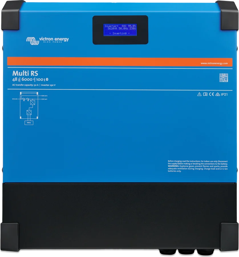
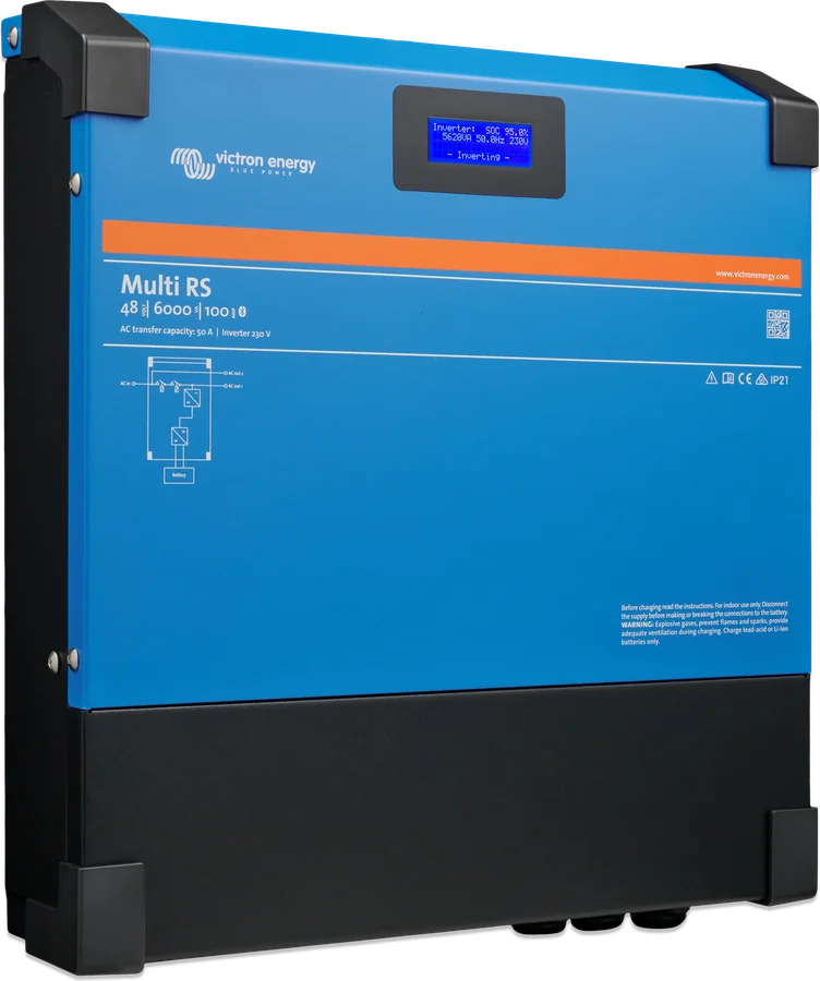
Multi RS 48|6000|100 — front with display
Multi RS 48/6000/100
A sine-wave inverter/charger with an automatic 50 A transfer switch for 48 V batteries — without built-in PV regulators. Panels are connected through separate MPPT solar charge controllers (on the DC side) or a PV inverter on the AC output.
- 48 V
- 230 V · 6 kVA
- 50 A transfer switch
- 11.2 kg
- VE.Can
48 V inverter and charger from the RS family
Multi RS converts 48 V battery voltage to 230 V, charges the battery from mains or a generator, and automatically switches loads between mains and battery. The datasheet describes three modes: emergency (switch to battery when mains fails), off-grid and with generator — the unit controls the generator to shorten its run time and adds battery power when the generator is not enough.
Unlike Multi RS Solar, it has no PV inputs. Panels are connected through MPPT solar charge controllers on the DC side or a PV inverter on the AC output, which Multi RS controls by frequency shift.
- full galvanic isolation between the battery and the AC side,
- for grid and generator: PowerControl and PowerAssist, 50 A transfer switch,
- three units — one per phase — form a three-phase system.
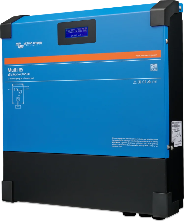

What Multi RS can do
6 kVA inverter
Continuous current 25 A AC. Peak 9 kW or 50 A for 3 s (motor starting) and 7 kW for 4 minutes — when the unit is cold.
88 A charger
From mains or generator up to 88 A at 230 V and 57.6 V (up to 5000 W). Together with a PV inverter on the output — up to 100 A.
PowerControl and PowerAssist
Grid or generator current limit, charging only from surplus. At peak, PowerAssist adds up to 6 kVA, or about 26 A.
Two AC outputs
AC-out-1 uninterrupted. AC-out-2 permanently connected to the AC input — no delay, for non-critical loads.
PV through MPPT or AC
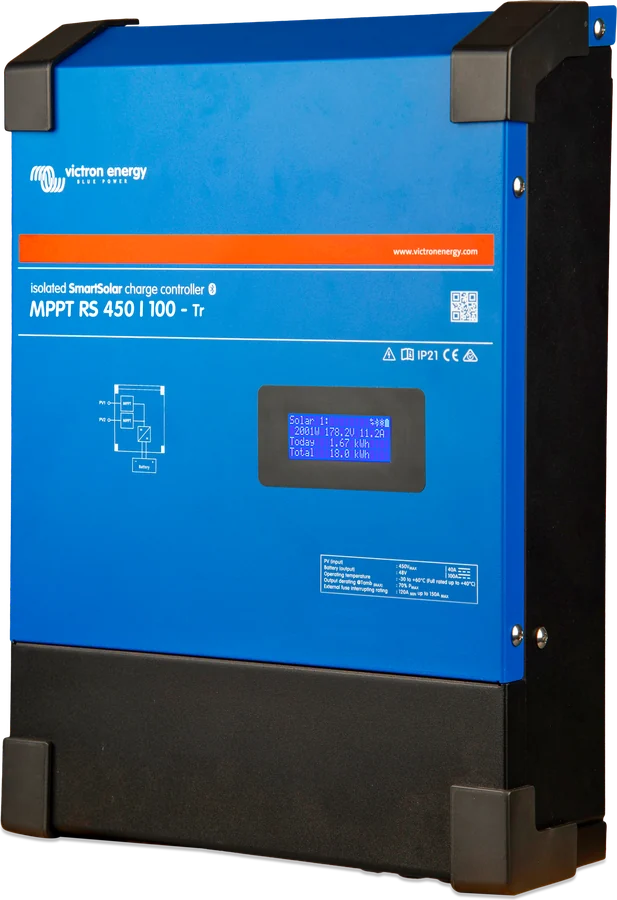
MPPT solar charge controllers (e.g. MPPT RS via VE.Can) or a PV inverter on the output up to 5000 W, controlled by frequency shift.
ESS and grid codes
Parallel operation with the grid: self-consumption or keeping the battery charged; export to the grid through the AC-in terminals after selecting the code.
VE.Can, VE.Direct, Bluetooth
GX only via VE.Can, VE.Direct to GlobalLink 520 or a computer, configuration in VictronConnect.
Relay and AUX inputs
Volt-free relay 4 A up to 35 V DC and 1 A at 70 V DC (including generator start and stop) — not for 230 V circuits. Two AUX inputs, e.g. feed-in blocking; do not connect them to battery poles.
Three phases
Up to three units, one per phase, via VE.Can — star (Y) only. No parallel operation and no split-phase.
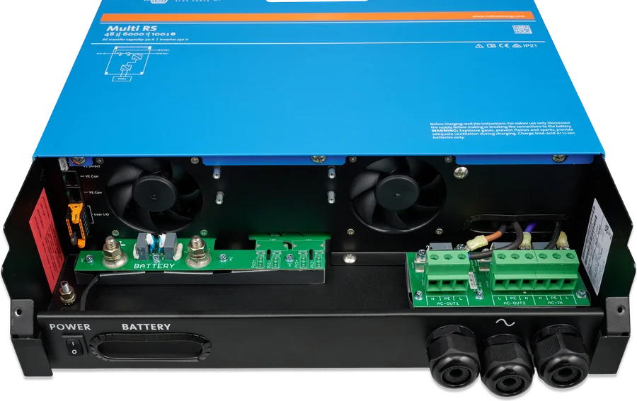
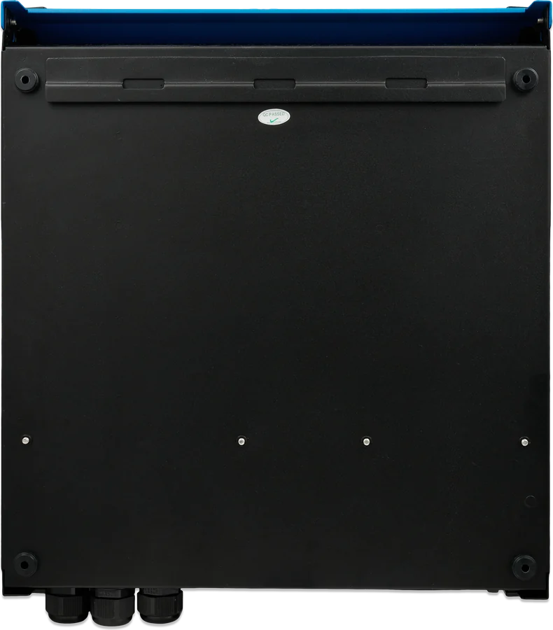
Main specifications
| Inverter | |
|---|---|
| Battery voltage | 38–62 V DC (start at 41 V, disconnect at 65.5 V) |
| Output | 230 V ±2%, 50 Hz ±0.1% (240 V and 60 Hz possible) |
| Continuous power | 25 °C: 4600 W at 46 V → 5200 W at 52 V; 40 °C: 4500 W; 65 °C: 3000 W |
| Peak power | 9 kW for 3 s, 7 kW for 4 min |
| Continuous / short-circuit current | 25 A AC / 45 A |
| Efficiency | 96.5% at 1 kW, 94% at 5 kW |
| No-load consumption | 20 W |
| Low battery voltage | shutdown 37.2 V, restart 43.6 V (adjustable) |
| AC input and charger | |
|---|---|
| AC input | 187–265 V, 45–65 Hz; switch and flow 50 A |
| Charging from AC | 88 A at 57.6 V (230 V, 25 °C), up to 5000 W |
| Total charging | 100 A (AC input + PV inverter on the output) |
| Absorption / float | factory default 57.6 / 55.2 V, range 36–60 V |
| Temperature sensor | included; voltage sense — yes |
| UPS specification | input 46 A, output 26 A, 6 kVA / 5 kW |
| Icw / Ipk | 500 A for 0.1 s / 2 kA |
- Enclosure
- steel, 462 × 425 × 127 mm, 11.2 kg
- Ingress protection
- IP21, protection class I
- Operating temperature
- −40 to +65 °C, fan cooling
- Grid system
- TN and TT only
- Battery
- M8 screws
- AC
- 10 mm² screw terminals
- Communication
- VE.Can, VE.Direct, Bluetooth
- Product code
- PMR482604000
The datasheet and the manual differ in a few places: continuous power at 25 °C (datasheet 4600–5200 W, manual 4800–5300 W), ingress protection (datasheet IP21, manual table IP20) and ambient temperature for installation (manual −40 to +60 °C). We have used the datasheet values. Separate issue: 30 A is the inverter output overcurrent protection from the data table, while the external breaker on AC-in and AC-out may be up to 50 A (manual, UPS specification).
Where the Multi RS sits in the system
Grid or generator on the AC input, 48 V battery through a fuse, panels through a separate MPPT. Hover over a diagram element or tap it. Schematic only.
- Mains / generator → AC-inUp to 50 A, TN or TT grid.
- AC-out-1Loads powered also from the battery; optional PV inverter.
- AC-out-2Only when powered from an external source.
- Battery → fuse35 mm² and 125 A up to 2 m, 70 mm² and 200 A up to 5 m.
- MPPT solar charge controllerPanels on the DC side — full charging from PV.
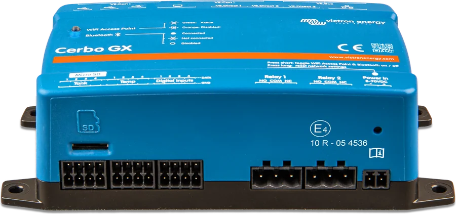
- GX (VE.Can)Monitoring, VRM and DVCC.
Multi RS, Multi RS Solar or MultiPlus-II?
Multi RS
48 V inverter/charger with no PV inputs. Choose this when you connect the panels through separate controllers or a PV inverter, or there is no PV at all.
48 V · 6 kVA · 88 AMulti RS Solar
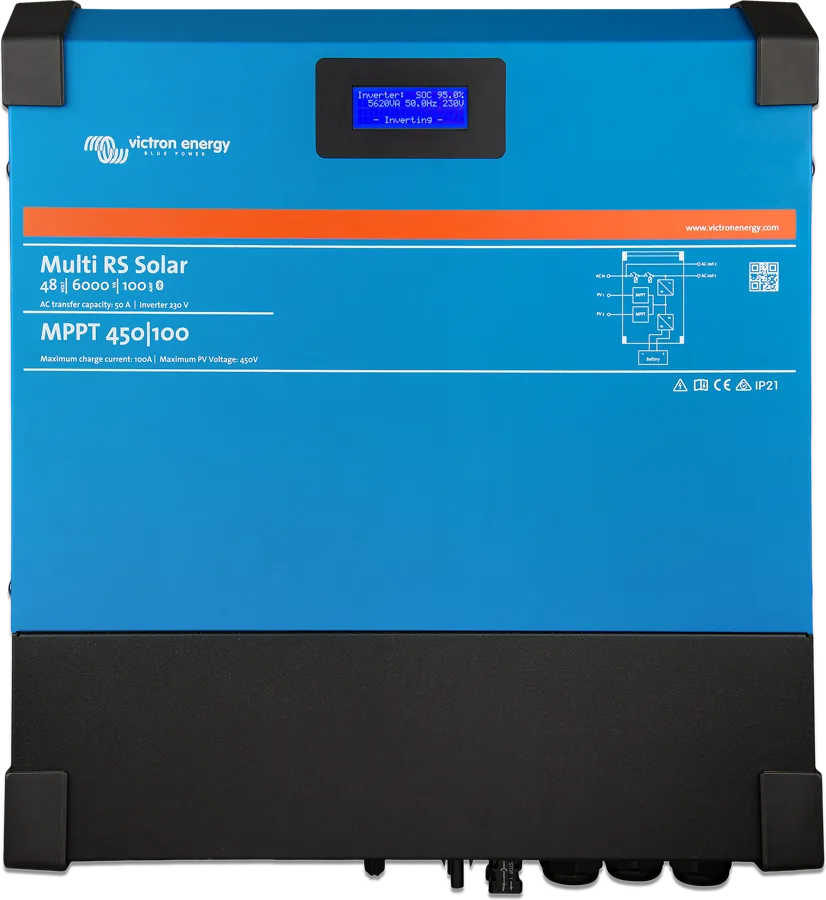
Version with two 450 V MPPT trackers inside — wall-mounted or in a 19" enclosure. Multi RS Solar · Multi RS19 Solar.
+ 2 × MPPT 450 VMultiPlus-II
When you need parallel operation, VEConfigure assistants or power other than 6 kVA. The three-phase VE.Can grid in Multi RS works differently from VE.Bus. MultiPlus-II card.
3–15 kVA · VE.BusInstallation rules
There may be 400–500 V DC inside even after switch-off. Disconnect all sources and wait at least 5 minutes. Do not remove the front cover — there are no user-serviceable parts inside. Installation only under the supervision of a qualified installer.
The enclosure must have a permanent connection to earth — via the AC input protective conductor or separately via the enclosure earth screw. In a mobile installation, connect the enclosure to the vehicle chassis.
Insert the main fuse only after all DC connections have been made. Reverse battery polarity will damage the device and is not covered by the warranty — check it with a multimeter.
- Location: vertically on a wall, 30 cm of free space above and below the unit, non-combustible surface, no direct sunlight, moisture, soot, dust or salt. Never directly above lead-acid batteries.
- Order: first check polarity and battery cables, then — if required — remote on/off, relay and communication.
- Battery terminals: ring terminal, flat washer, spring washer, nut; torque up to 14 Nm with an insulated socket. Do not undo the lower nut soldered to the PCB.
- AC: screw terminals, insulation stripped back by 10 mm, torque up to 1.2 Nm; do not swap L and N. A disconnector must be fitted on both the AC and DC side.
| Cable length | Cross-section per pole | DC fuse | Minimum battery |
|---|---|---|---|
| 0–2 m | 35 mm² | 125 A | 200 Ah lead-acid or 100 Ah lithium |
| 2–5 m | 70 mm² | 200 A |
Battery cables: flexible Class 5 copper stranded wire (individual strands max. 0.4 mm), insulation min. 90 °C; voltage drop above 2.5% is not acceptable. Batteries with HB flammability rating or better. 50 A switch on the AC input and output. The earth relay connects N to the enclosure without external AC; the built-in RCMU switches off the inverter at leakage current. More: earthing and RCD, cable cross-sections and DC fuses.
How to set it up
All settings — including grid settings — are made in VictronConnect; there are no VEConfigure assistants. Bluetooth is enabled by default (PIN 000000 or from the sticker). On Windows you need a VE.Direct–USB interface.
- Battery: fixed 48 V voltage; presets Normal, High and LiFePO4 2-wire BMS; for LiFePO4, charging is blocked below 5 °C. The built-in battery monitor can control a relay.
- Remote and BMS: by default REMOTE_H and REMOTE_L are bridged — without the bridge the device will not switch on. When a BMS is connected, the device enters “BMS controlled” semi-permanently (power-off does not clear it) — this is cleared by the “BMS controlled” field in the battery settings or by a factory reset.
- BMS: Victron LiFePO4 batteries with Victron BMS — Lynx Smart BMS NG via VE.Can, smallBMS NG via contacts to the I/O terminal block (”2-wire BMS” mode). Third-party BMS-Can — via the GX device BMS-Can port.
- ESS: modes with BatteryLife (lead-acid), without BatteryLife (lithium), Keep batteries charged (default, also off-grid) and External control. Without a grid meter, ESS supplies only critical loads from the battery.
- Grid code: feeding into the grid requires a grid code and usually the operator’s approval; after the first setup, changes require a password. A country being listed does not mean certification — check the current certificates. Energy meter: Victron VM-3P75CT only.
- Generator (firmware from v1.11): input type Generator, “Moderate generator load changes” enabled, “Energy meter support” disabled, current limit according to the generator, UPS function disabled. Without a grid code — “None”; with a grid code — LOM detection “no LOM detection” and “Feed-in allowed” disabled. ESS mode remains Keep batteries charged; other ESS settings do not apply. Never disable LOM when the Multi RS is connected to the grid.
Three phases (firmware from v1.13): up to three units, one per phase, connected via VE.Can with terminators, star only with distributed N. Each unit has separate AC and DC protection and a common battery bank. Change the configuration before connecting loads — the AC output then disappears for a few seconds. Do not enable “Continue with missing phase” with three-phase loads. Mixing Inverter RS with Multi RS in three-phase systems is not supported. The manufacturer does not recommend such systems for untrained or inexperienced installers.
What Multi RS does not do
Section “Limitations” in the manual and notes from other sections. The manufacturer states that limitations may change with firmware updates — before buying, check with the seller that the device is suitable for the application.
No parallel operation
One unit operates per phase. The manual does not state whether current hardware will receive this function in firmware.
No VEConfigure assistants
Only what is in VictronConnect — no advanced VE.Bus device control.
ESS not fully
Not all grid codes are available. There is no ESS control from VRM.
AC charging up to 5000 W
At 230 V — a higher AC voltage raises this limit slightly, a lower one reduces it. In practice it is lower at high ambient temperature or poor airflow.
Limit after 4 minutes
After about 4 minutes of heavy load, inverter current is limited to 25 A AC.
AC-out-2 without control
The output is permanently connected to the AC input — it cannot be programmed or controlled by relay.
No VE.Smart
Does not work with the VE.Smart network, for example with Smart Battery Sense.
PV inverter — up to about 95%
With a PV inverter on the output, the battery will not reach 100% — full charging from PV requires an MPPT controller on the DC side.
No split-phase and delta
Only one phase or three phases in star.
Most common faults
Typical situations described in the manual. Check the error number from the display or VictronConnect in the RS device error codes section — Multi RS uses the same numbering as MPPT controllers and other RS devices.
The device does not switch on
Check the REMOTE_H–REMOTE_L bridge on the User I/O terminal strip (factory fitted), the switch in the On position, and the “Mode” setting in VictronConnect. In Remote “2-wire BMS” mode, without a BMS the unit may not start; start requires at least 41 V.
Shuts down under heavy load
Overload: after three restarts within 30 s, the unit shuts down. Disconnect some loads, switch them off and on again.
Shuts down on low battery
After three shutdown and restart cycles it stops trying. Switch it off and on, and reduce the load. If the battery is completely empty and there is an allow-to-charge signal, temporarily disable this function in VictronConnect.
Overtemperature
Restarts after 30 s, without a permanent shutdown. Check the ambient temperature, 30 cm clearance above and below the unit, and that ventilation is unobstructed.
Battery does not charge
The battery is full, the charging settings are too low, charging is limited by external control (ESS, DVCC), or by battery temperature.
Battery is chronically undercharged
Most often caused by voltage drop in the cables — above 2.5% is unacceptable (cable cross-section, crimping of terminals, loose terminals, fuses) — or incorrect temperature compensation.
Battery overcharged
Charging voltages too high, equalisation of a battery that does not tolerate it (sealed and lithium batteries are not equalised), or an old, damaged battery.
Frequent disconnection from the grid
In a three-phase system or with a generator, the UPS function can be too sensitive — disable UPS function. The status “Why is AC in disconnected?” in VictronConnect also provides clues.
GX cannot see the device
Multi RS connects to a GX device only via VE.Can (with terminators at both ends of the bus) — not via VE.Direct.
Frequently asked questions about Multi RS
How does Multi RS differ from Multi RS Solar?
It has no built-in MPPT controllers or PV inputs and is lighter (11.2 kg). The inverter and mains charger ratings are the same: 25 A AC, 9 kW for 3 s, 88 A charging. Multi RS Solar datasheet.
How do you connect the panels?
Via an MPPT controller on the DC side — for example an MPPT RS connected via VE.Can — or via a PV inverter on the AC output (up to 5000 W, 1:1 rule relative to the Multi RS power). With a PV inverter, the battery will charge only to about 95%.
Which cable and fuse do you need for the battery?
Up to 2 m: 35 mm² and a 125 A fuse; from 2 to 5 m: 70 mm² and 200 A. Minimum battery: 200 Ah lead-acid or 100 Ah lithium. M8 terminals, torque up to 14 Nm.
Can I connect two Multi RS units in parallel?
No. You can build a three-phase system from three units (one per phase), but parallel operation on a single phase is not supported.
How do you connect the GX device?
Only via VE.Can — a VE.Direct connection does not work with GX. VE.Direct is for the GlobalLink 520 or a computer. Terminators are required at both ends of the VE.Can bus.
Can I use it with a generator?
Yes, from firmware v1.11. Set the input type to Generator, enable “Moderate generator load changes”, match the current limit to the generator, and disable the UPS function. The relay can start and stop the generator according to load, voltage or SOC.
The unit does not switch on — what should I check?
The REMOTE_H–REMOTE_L bridge on the User I/O terminal strip (factory fitted), the switch position (On), and the “Mode” setting in VictronConnect — the Off setting overrides the switch. In Remote “2-wire BMS” mode, the manual says once that without a BMS the unit will not start, and elsewhere that with the bridge fitted it will start with charging locked out. Also check the Aux “Safety switch” function and battery voltage — start requires at least 41 V.
What should be connected to AC-out-2?
Non-critical loads, for example a water heater or air conditioner. AC-out-2 is permanently linked to the AC input: it disconnects immediately when the system switches to battery and reconnects immediately when mains power returns. Its load is taken into account by PowerControl and PowerAssist.
Manufacturer documentation
The Multi RS 230 V manual contains sections carried over from the Solar version (including the PV disconnect, class A modules, texts about PV at error 29) — on this page we do not repeat them, because Multi RS has no PV inputs. We describe differences between the datasheet and the manual in the Data section.
Content checked against Victron Energy documentation (datasheets and manuals) — as of 22 September 2026. Report a content error · Revision log