
01What they are and when they are needed
According to Victron, in 99% of cases Assistants replace a separate PLC controller — for example for load shedding, PV optimisation or automatic generator start. At the same time, in 95% of installations no Assistant is needed: standard settings or a Virtual Switch are enough.
- VEConfigure only. Assistants are added in VEConfigure on Windows. VictronConnect does not support them, and when you create a parallel system in VictronConnect the Assistants are removed.
- Firmware. The Assistants tab is available in firmware 2xx, 3xx and 4xx. Version 4xx (new microcontroller, number from 26 or 27) has both Assistants and Virtual Switch; version 1xx has only Virtual Switch. You must not mix 1xx with 2xx–4xx versions in one system.
- Combining. You can use multiple Assistants, even the same one several times. They run from top to bottom, so order matters. An “ON” condition always overrides “OFF”, and several conditions in one list work as “or”.
02How to add an Assistant
- Connect to the device in VEConfigure 3 (via MK3-USB or remotely via Remote VEConfigure) and open the Assistants tab.
- Choose an Assistant from the list and click Add assistant. It will appear in italics in the “Used assistants” list — this means it is not yet configured.
- Click Start assistant and go through the pages. The first page contains important information about how it works — read it. When you finish, the Assistant name will change to normal text.
- Click Send settings and confirm that you also want to send the Assistant configuration. The device will switch off briefly while saving and then restart — plan this so the loads can be without power.
Updating an Assistant: with internet access, VEConfigure downloads new versions automatically, and after connecting to the device it marks Assistants that need updating with an asterisk. Right button → update, go through the pages (check the values) and Send settings — the system will switch off briefly again.
Practice without a device: in VEConfigure, Port selection → Fake target with full options shows the Assistants tab without connected hardware.
03Most commonly used Assistants
| Assistant | What it is for |
|---|---|
| ESS | grid-connected energy storage system — priority for PV power, battery charge and discharge (described below) |
| PV Inverter Support | off-grid systems with a grid-tie PV inverter on the MultiPlus AC output (AC coupling): limits the PV inverter power by shifting frequency when the battery is charging. It does not work with the grid connected. Do not combine it with ESS — ESS is used in grid-connected systems |
| Generator start/stop | automatic generator start and stop according to SoC and load (a simpler version of this function is in Virtual Switch); also used to ignore the AC input |
| Two-Signal BMS support | lithium batteries with a BMS that controls two voltage-free contacts (for example the former Lynx Ion BMS and batteries from other manufacturers): the “full” signal switches to float or turns off charging, the “empty” signal turns off the inverter. AUX inputs and current firmware are required |
| VE.Bus BMS support | for batteries with VE.Bus BMS — according to Victron’s list, not needed from VE.Bus firmware 489 onwards (update the firmware first) |
| AC Current sensor | reading PV inverter current using a current sensor connected to VE.Bus |
| Input current limit control | automatic change of the input current limit according to the AUX input — for example a generator with variable speed or two types of shore power plugs |
| Charge current control | charge current dependent on the active AC input (Quattro) or the AUX input |
| Silence fan | switching off fans at night with an external switch (boats, campervans) |
| Safety switch | connecting a safety switch to the VE.Bus system |
| Programmable relay, Relay locker, General flag user | advanced Assistants — custom relay and flag logic, often used several times in one device |
| Hub-1, Hub-2, Hub-4 | obsolete — replaced by ESS, do not use in new installations |
04ESS Assistant
ESS (Energy Storage System) is an assistant for home energy storage systems that work with the grid. How to design the whole system: home system diagram with ESS; how much capacity makes sense: ESS battery bank calculator.
- Requirements: MultiPlus, MultiGrid and Quattro with firmware 422+, a GX device with Venus OS v2.15+, current MPPT charge controller firmware. For use with DVCC, the ESS assistant must be version 164 or newer.
- Order in VEConfigure: grid code on the Grid tab (password from the distributor) → add the ESS assistant → check the General tab (the assistant enables the built-in battery monitor — leave it enabled, even if you have a BMV or a battery with CAN) → check the Charger tab (the assistant sets the battery type and disables Storage mode; the Lithium option must match the battery selection in the assistant).
- The grid code is mandatory — with code “None”, the system will not power loads from the battery when the grid is present, even without exporting energy.
- What ESS overrides: it disables PowerAssist and the dynamic current limiter; it ignores the DC input low shut-down, restart and pre-alarm thresholds on the Inverter tab — instead it uses dynamic cut-off depending on discharge current (for 12 V, for example, 10 V at high current and 11.5 V at low current). The input current limit works in both directions.
- Sustain: when the battery reaches the minimum state of charge (SoC), the system keeps it charged from the grid at a current of up to 5 A per unit (for lithium, 12.5 V on 12 V; ×2 for 24 V, ×4 for 48 V).
- ESS modes (Optimized with BatteryLife and without, Keep batteries charged, External control), minimum SoC and grid setpoint (default 50 W) are set on the GX device (Settings → ESS), not in VEConfigure.
- Before ESS starts using the battery, it performs a relay test (about 1 minute of inverter operation) — status in GX: Advanced → ESS Relay test.
- ESS must not be used in vehicles or on boats — the shore power plug can remain live for a few seconds after disconnection.
When an ESS system draws from the grid even though it should not: ESS draws from the grid.
05Assistants in parallel and three-phase systems
- ESS, PV Inverter Support, VE.Bus BMS and Two-Signal BMS must be uploaded to every unit. In Two-Signal BMS, the full configuration is done only on the unit physically connected to the BMS, and on the others you select that the BMS is connected to another device.
- Other assistants (generator start, relay locker, etc.) may have different settings in each unit — the same applies to programmable relays.
- In a multi-unit system, start VEConfigure from VE.Bus System Configurator or Quick Configure to send settings to the correct devices.
Devices this applies to
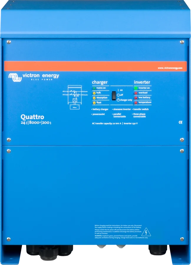
 QuattroInverter/charger 3–15 kVA with two AC inputs — mains and generator without an external changeover switch.
 MultiPlus-IIInverter/charger with UPS function: pure 230 V sine wave, PowerAssist supports a weak shore connection.
 MultiPlus-II GXMultiPlus-II with built-in GX device, display and Wi-Fi — VRM without a separate Cerbo.
 MK3-USB interfaceCable between the VE.Bus port and a computer — without it you cannot change settings or update the MultiPlus.
Related
- VEConfigure — connection, tabs, Virtual Switch.
- DVCC — when GX and the battery control charging.
- Venus OS and Remote Console — ESS settings on GX.
Sources
- Assistants — what they are, linking, firmwarevictronenergy.com · EN
- How to add and configure an Assistantvictronenergy.com · EN
- Overview of available Assistantsvictronenergy.com · EN
- ESS Design & Installation manual — ch. 4 Configuration, ch. 6 Controlling depth of dischargevictronenergy.com · EN
- Parallel, split- and three-phase VE.Bus systems — Assistantsvictronenergy.com · EN
- VE.Bus firmware versions explained (v24)victronenergy.com · PDF · EN