
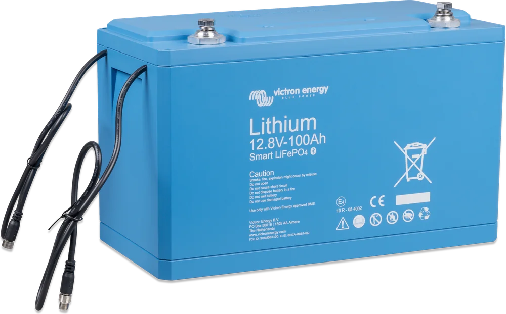
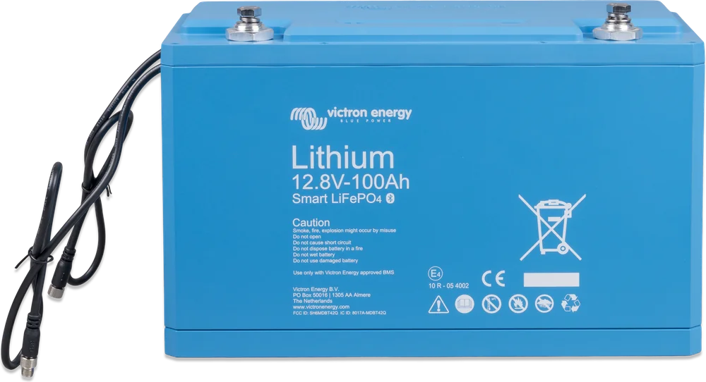
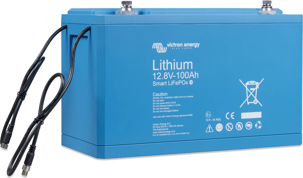
LiFePO4 12.8 V 100 Ah Smart — top view at an angle
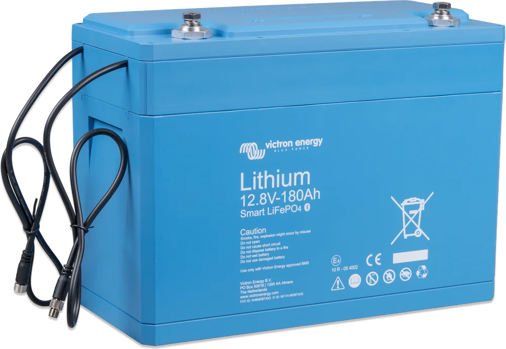
LiFePO4 12.8 V Smart
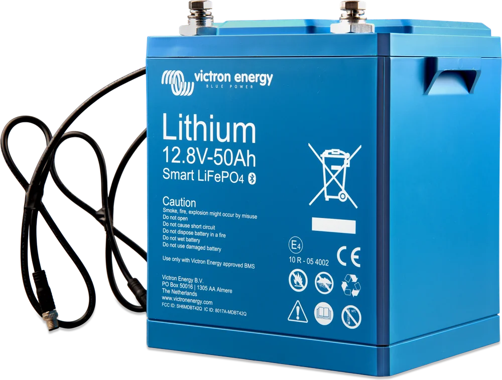
Victron lithium batteries with Bluetooth, built-in balancing and cell monitoring. Lighter and longer-lasting than lead-acid batteries — they work only with an external BMS.
- 12.8 V (also 25.6 V)
- 50–330 Ah
- Bluetooth
- charging 5–50 °C
- IP22
A battery that is not killed by undercharging
Lead-acid batteries (including AGM and gel) are damaged by sulphation: when they run for a long time without a full charge or are left partly discharged over winter on a yacht or in a campervan. A LiFePO4 battery does not have this problem — it does not have to be charged fully, and according to the manufacturer, partial charging can even slightly extend its service life.
The nominal cell voltage of LiFePO4 is 3.2 V. A 12.8 V battery has 4 cells connected in series, 25.6 V has eight.
- 92% efficiency in a full cycle — compared with about 80% for an average lead-acid battery (manufacturer’s data),
- up to 70% less space and weight than lead-acid with the same usable energy,
- 2,500 cycles at 80% depth of discharge (DoD) — and 5,000 at 50%.
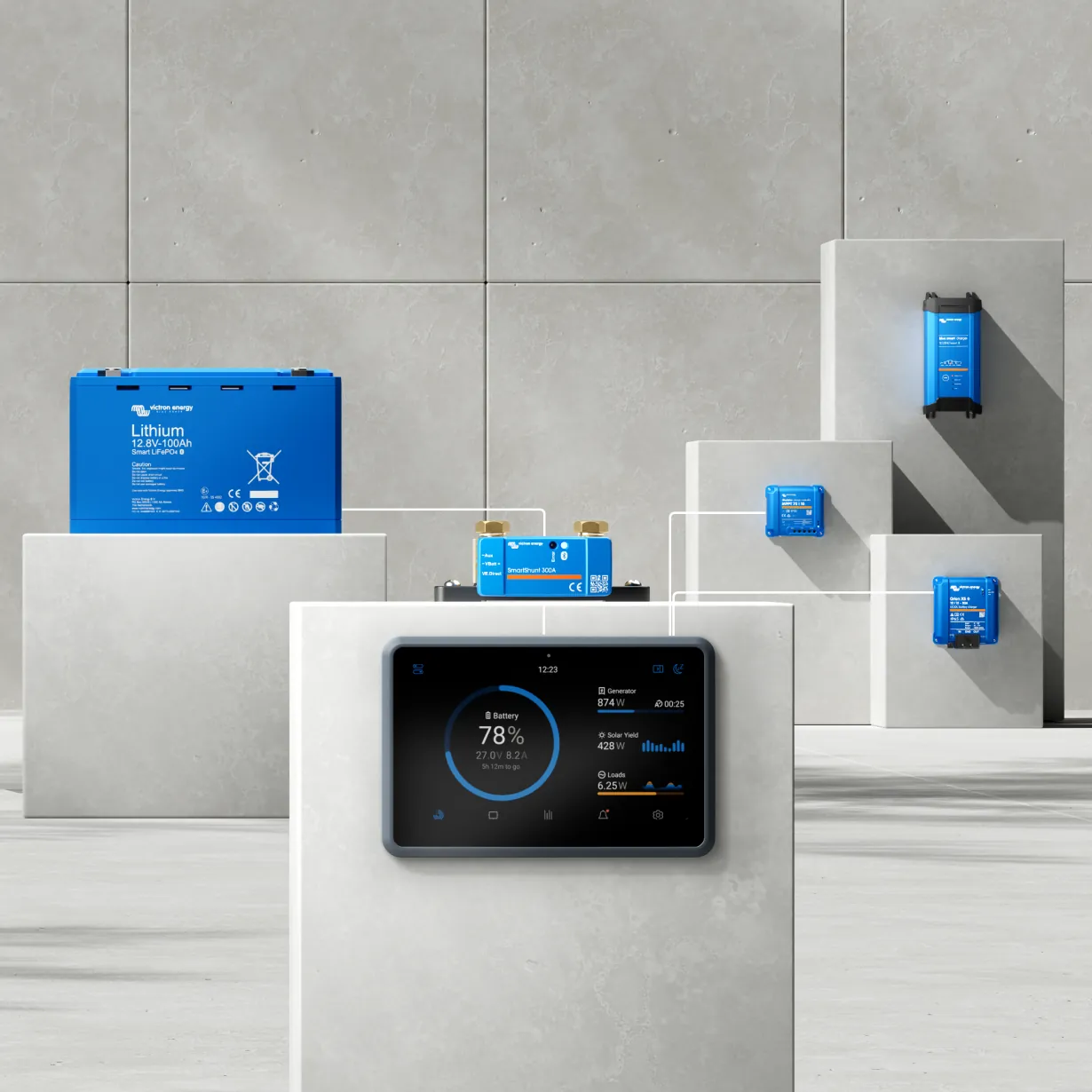
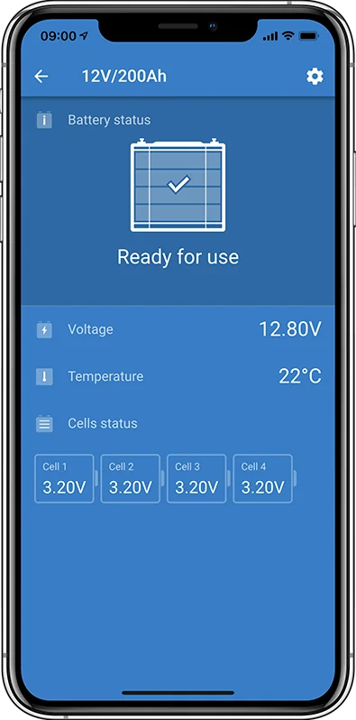

What is inside a Smart battery
Bluetooth
It shows the voltage of each cell, temperature and alarm status in the VictronConnect app. When Instant Readout is enabled (disabled by default), key data are visible already in the device list, without connecting to the battery.
Cell balancing
The built-in circuit balances the cells during the absorption phase at 1.8 A (50 Ah model: 1 A). With light cycling, you need at least 2 h of absorption per month, and in heavily cycled off-grid and ESS systems — 4–8 h per month. Full charging once a week is required, among other cases, with series-connected batteries, frequent cycling, high discharge currents, and short charging periods or charging voltages that are too low. Uneven cells are easy to spot in the app.
Cell monitoring
The battery monitors voltages and temperatures itself and sends signals to the BMS via cables with M8 plugs (50 cm).
Low resistance
Internal resistance 0.8–2 mΩ — high surge currents, for example when starting the inverter, without a large voltage drop.
Operating temperature
Charging is allowed from +5 to +50 °C — below this threshold the BMS stops it. Discharge is allowed from −20 °C, but at −20 °C the battery will deliver only about half its capacity.
Storage
A fully charged battery can be stored for up to a year at 25 °C without topping up; the permitted storage range is −45 to +70 °C. The enclosure is IP22, so only in a dry place.
Six 12.8 V models and two 25.6 V models
| Model | Energy | Capacity at 25 / 0 / −20 °C | Max / recommended discharge | Max / recommended charge | Weight | Dimensions (H × W × D) |
|---|---|---|---|---|---|---|
| 12.8 V | ||||||
| 12.8/50 | 640 Wh | 50 / 40 / 25 Ah | 100 / ≤50 A | 100 / ≤30 A | 7 kg | 199 × 188 × 147 mm |
| 12.8/100 | 1,280 Wh | 100 / 80 / 50 Ah | 200 / ≤100 A | 200 / ≤50 A | 14 kg | 197 × 321 × 152 mm |
| 12.8/160 | 2048 Wh | 160 / 130 / 80 Ah | 320 / ≤160 A | 320 / ≤80 A | 18 kg | 237 × 321 × 152 mm |
| 12.8/180 | 2304 Wh | 180 / 150 / 90 Ah | 360 / ≤180 A | 360 / ≤90 A | 18 kg | 237 × 321 × 152 mm |
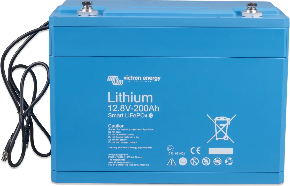
| 12.8/200 | 2,560 Wh | 200 / 160 / 100 Ah | 400 / ≤200 A | 400 / ≤100 A | 20 kg | 237 × 321 × 152 mm |
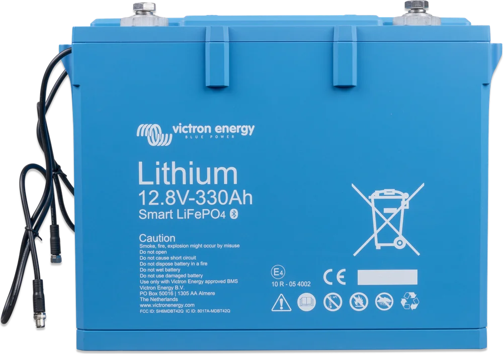
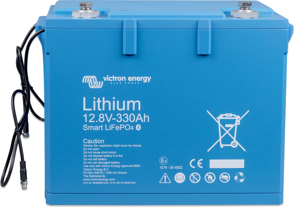
| 12.8/330 | 4220 Wh | 330 / 260 / 160 Ah | 400 / ≤300 A | 400 / ≤150 A | 29 kg | 265 × 359 × 206 mm |
| 25.6 V | ||||||
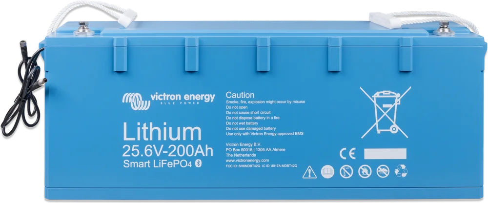
| 25.6/100 | 2,560 Wh | 100 / 80 / 50 Ah | 200 / ≤100 A | 200 / ≤50 A | 28 kg | 197 × 650 × 163 mm |
| 25.6/200 | 5,120 Wh | 200 / 160 / 100 Ah | 400 / ≤200 A | 400 / ≤100 A | 39 kg | 237 × 650 × 163 mm |
Capacity drops in the cold: at 0 °C the battery delivers about 80%, and at −20 °C about 50% of nominal capacity (at a discharge current of ≤1C). Bear this in mind when choosing a battery for a winter campervan.
- Charge voltage
- 12.8 V: 14.0–14.4 V (recommended 14.2 V); 25.6 V: 28.0–28.8 V (recommended 28.4 V); absorption 2 h; temperature compensation 0 mV/°C
- Float voltage
- 12.8 V: 13.5 V; 25.6 V: 27.0 V
- Discharge cut-off
- 11.2 V (25.6 V: 22.4 V)
- Charge temperature
- +5 … +50 °C
- Discharge temperature
- −20 … +50 °C
- Storage
- −45 … +70 °C, up to 1 year (charged, 25 °C)
- Cycles (≥80% capacity)
- 2500 / 3000 / 5000 at 80 / 70 / 50% DoD
- Capacity loss
- <1% per 100 cycles (25 °C, 100% DoD)
- Terminals
- M8 thread (330 Ah: M10)
- Ingress protection
- IP22 (indoor use only, in a dry place)
This battery must not be used without a BMS
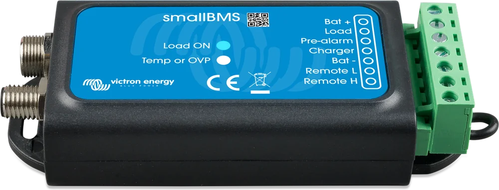
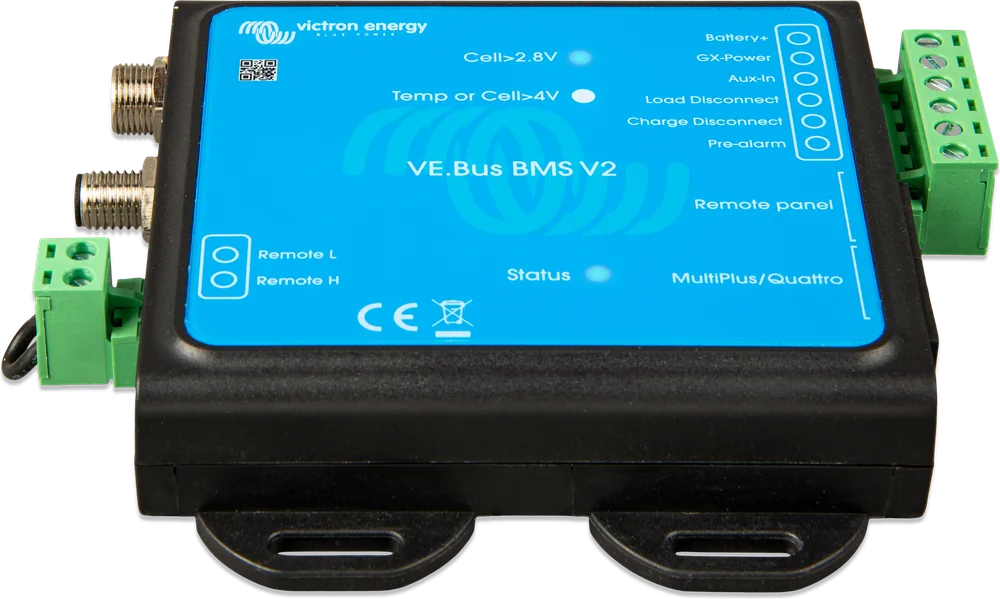
The Smart battery does not disconnect itself. It measures the cells and sends signals via M8 cables to an external battery management system (BMS). The BMS switches off the loads or charging when something is wrong:
- warning, when a cell drops below 3.1 V (adjustable 2.80–3.15 V according to the manual; the datasheet gives 2.85 V),
- load disconnection below 2.8 V per cell (adjustable 2.6–2.8 V),
- charging stop above 3.75 V per cell or at temperature that is too high or too low.
Up to 20 batteries can be connected to one BMS — the BMS cables are linked in a chain from battery to battery.
Which BMS for which system
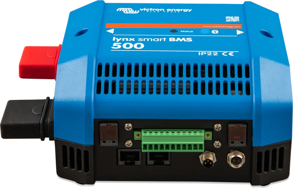
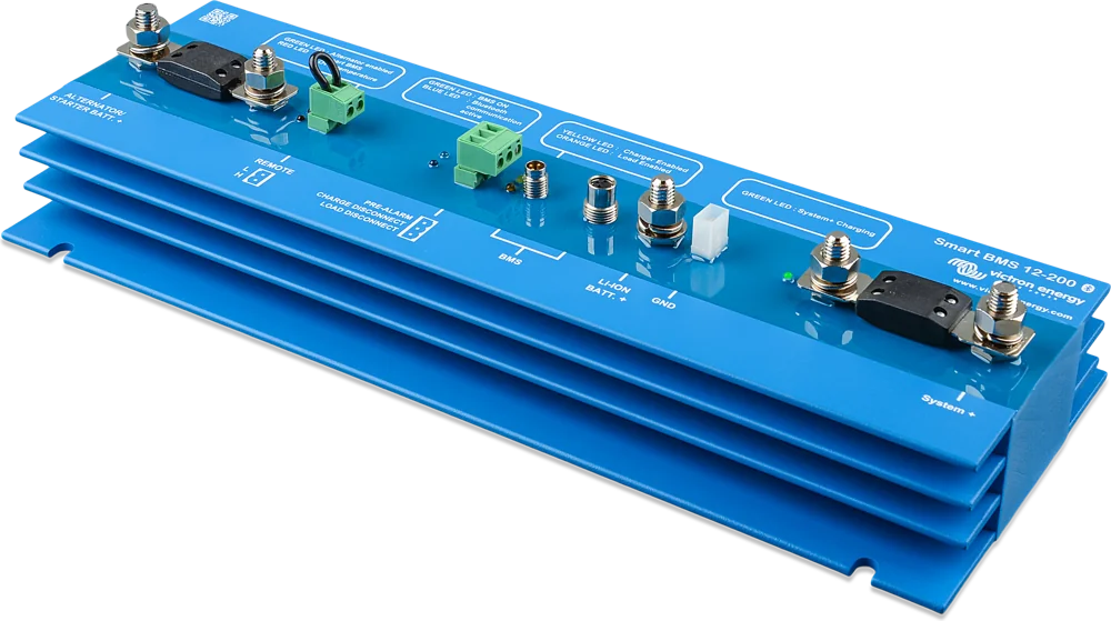
| smallBMS | VE.Bus BMS V2 | Lynx Smart BMS | Smart BMS CL 12/100 | Smart BMS 12/200 | |
|---|---|---|---|---|---|
| System voltage | 12/24/48 V | 12/24/48 V | 12/24/48 V | 12 V | 12 V |
| How it disconnects | by controlling loads and chargers | by controlling loads and chargers | ATC/ATD and DVCC signals; 500 / 1000 A contactor as emergency protection | by controlling loads and chargers | system output 200 A |
| Alternator input | no | no | no built-in alternator port with current limiting | 100 A | 100 A |
| Battery monitor | no | no | yes | no | no |
| Bluetooth | no | no | yes | yes | yes |
| Control via GX / DVCC | no | GX/DMC: control of inverter/charger state | yes (DVCC) | no | no |
| When to choose | simple DC systems | system with MultiPlus/Quattro | yacht, campervan, digital integration | 12 V with alternator | 12 V with alternator, loads and inverter |
The table covers currently available BMS units (the manufacturer has discontinued the older VE.Bus BMS and BMS 12/200). Batteries from the LiFePO4 NG family are a separate series that works with the NG BMS range — this page does not cover them.
How the BMS protects the battery
Example with a BMS controlling loads and chargers (for example VE.Bus BMS V2). Hover over or tap a diagram element to see its description.
- Battery → BMS (M8)The battery measures cell voltage and temperature; it sends any alarm to the BMS.
- BMS → chargers“Charge disconnect”: stop charging at 3.75 V per cell or at an invalid temperature.
- BMS → loads“Load disconnect”: disconnect the loads below 2.8 V per cell.
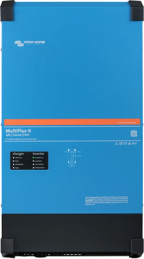
- BMS → MultiPlus-II (VE.Bus)VE.Bus BMS V2 controls the inverter directly.
- DC busbarCurrent flows directly from the battery — the BMS only sends commands.
With a Lynx Smart BMS variant, it first shuts devices down using ATC/ATD signals and via DVCC, and the contactor disconnects the installation from the battery only as an emergency measure if those methods fail. Complete diagrams for each BMS are in the battery manual (the BMS selection section).
Series, parallel and mixed
Parallel
Several 12.8 V batteries connected in parallel increase capacity. Max. 20 batteries in a system — up to 84 kWh.
4 × 12.8/200 = 800 Ah · 10.2 kWh25.6 V batteries are best
The manufacturer recommends building a 24 V system from 25.6 V batteries. Two 12.8 V batteries in series will also work, but they need more frequent full charging (once a week), because one battery’s balancer will not equalise differences between batteries.
2 × 25.6/200 parallel = 400 AhTwo 25.6 V in series
A 48 V system is best built from pairs of 25.6 V batteries. Four 12.8 V batteries in series will work, but they need balancing more often.
up to 102 kWh in a 24/48 V systemAccording to the manual: a fuse on the positive terminal of each parallel battery (or each string) and a fuse on the bank’s main positive cable. Connect the installation cables “diagonally” across the bank so current flows evenly through each battery; main cable cross-section = branch cable cross-section × number of branches. Do not connect the midpoint of the strings. Batteries leave the factory charged to about 50% — before series connection, charge each one separately to full (with a charger controlled by the BMS).
Parallel: mixed capacities and age are allowed. Series: same capacity and part number, age difference up to 3 years.
A battery’s balancer equalises only its own cells — it will not compensate for differences between batteries connected in series. Fewer batteries in series means a lower risk of imbalance — that is why the manufacturer recommends 25.6 V instead of pairs of 12.8 V.
Battery manual: up to 20 batteries in one system in total, regardless of the Victron BMS used. Only a few Lynx Smart BMS units can be connected in parallel (up to 5, with the correct firmware) — see the Lynx Smart BMS datasheet for details.

What to watch out for
Charging is allowed from +5 to +50 °C. The BMS will stop charging at too low a temperature — in a winter campervan, install the battery in the heated part of the vehicle.
Indoor use only, in a dry place; 20 mm of free space on all four sides of the battery (batteries warm up). When working on the terminals, remember: they are always live; use insulated tools, remove metal jewellery and avoid short circuits. Terminal tightening torques: 50–100 Ah and 25.6 V/100 Ah — 10 Nm (M8), 160–200 Ah and 25.6 V/200 Ah — 14 Nm (M8), 300–330 Ah — 20 Nm (M10). When you connect it for the first time, VictronConnect may offer a firmware update — do it.
After cut-off due to low battery voltage, a small reserve remains. Even a constant 10 mA load can damage a 200 Ah battery left discharged for more than 8 days.
Batteries may be installed upright or on their side, but not with the terminals facing down. 330 Ah model — upright only.
Max. charging current can be as high as 2C, but the manufacturer recommends about 0.5C (e.g. ≤50 A for 100 Ah). Charging voltage: for 12.8 V — absorption 14.2 V and float 13.5 V; for 25.6 V — absorption 28.4 V and float 27.0 V.
A charged battery can be stored for up to a year (at 25 °C). Storage is allowed from −45 to +70 °C.
The enclosure is IP22 — protect the battery from water and condensation.

Most common questions about LiFePO4 Smart batteries
Can I connect a Smart battery without a BMS?
No. A Smart battery has no internal disconnect switch — it only measures cells and sends signals. Without a BMS, nothing will stop charging during overcharge or disconnect loads during deep discharge, and that damages the cells.
Does the Smart battery show state of charge as a percentage?
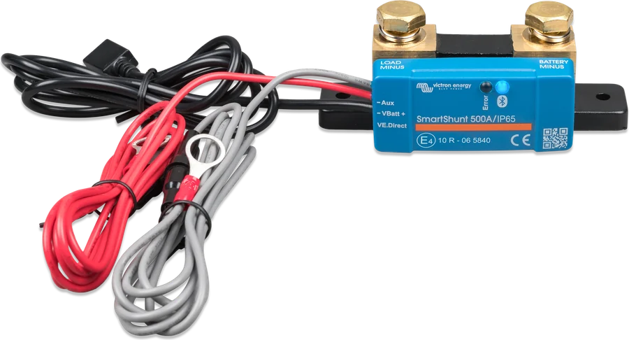
The app shows cell voltages, temperature and alarms. A battery monitor will show state of charge and runtime — for example SmartShunt or a Lynx Smart BMS with a built-in monitor.
What charging current should I set?
At most the value given in the table (for example 200 A for 100 Ah), but the manufacturer recommends much less: ≤50 A for 100 Ah, ≤100 A for 200 Ah. Gentler charging is better for service life.
Can I charge from the vehicle alternator?
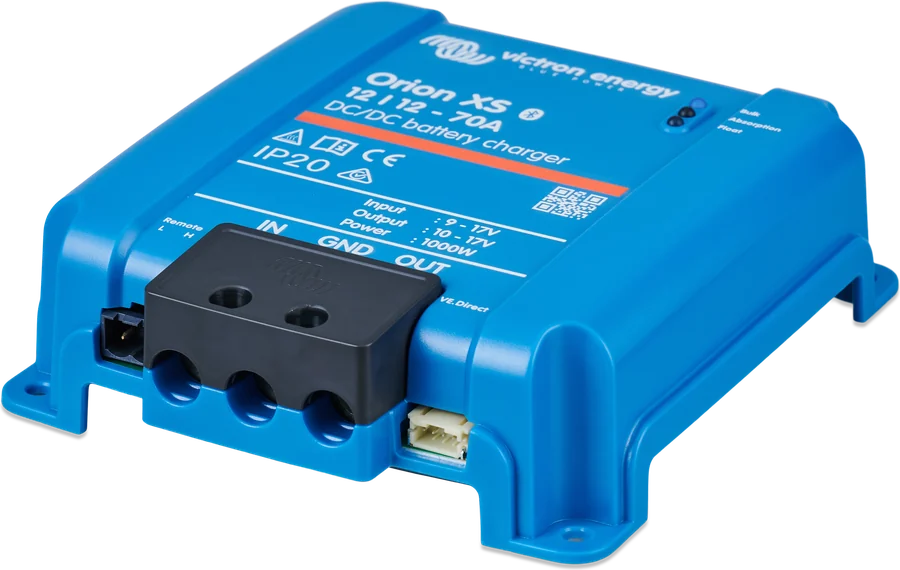
Yes, as long as the alternator is not overloaded. The battery manual gives four methods: an alternator with a current at least twice the battery capacity (in A and Ah), an alternator regulator with a temperature sensor, a DC-DC charger (for example Orion XS), or a BMS with an alternator port that limits current (Smart BMS CL 12/100, Smart BMS 12/200). Lynx Smart BMS does not have a built-in alternator port with current limiting.
Can batteries of different capacities be connected?
According to the battery manual: in a parallel connection, batteries of different capacities and ages may be connected. In a series connection (including a string in a series-parallel bank), batteries must have the same capacity and the same part number, and the age difference should not exceed 3 years. The whole series string can be added or replaced as one unit.
At what temperature may the battery be charged?
From +5 to +50 °C — below this threshold the BMS will stop charging. Discharging is possible from −20 °C, but at that temperature the battery will deliver about half of its capacity. In a winter campervan, install it in the heated part of the vehicle.
At what current and to what voltage should I charge?
Maximum charge current can reach 2C, but the manufacturer recommends about 0.5C (for 100 Ah that is no more than 50 A). Voltages: for 12.8 V, absorption 14.2 V and float 13.5 V; for 25.6 V — 28.4 V and 27.0 V.
How do I set the battery for winter?
Charge it fully and disconnect it — that way it can be stored for up to a year at 25 °C. Do not leave the battery discharged: after BMS cut-off only a small reserve remains, and a constant load of around 10 mA can damage a 200 Ah battery within eight days.
In what position can it be mounted?
Vertical or on its side, but never with the terminals facing down; the 330 Ah model must be installed vertically only. Leave 20 mm of free space on all four sides. Tightening torques: 10 Nm (M8) for 50–100 Ah, 14 Nm (M8) for 160–200 Ah and 20 Nm (M10) for 300–330 Ah.
Manufacturer documentation
- 12.8 V and 25.6 V Smart battery datasheetPDF · EN
- BMS system overviewPDF · EN
- Lithium Smart battery manual (BMS selection, wiring diagrams)PDF · EN
- Product page at the manufacturervictronenergy.com
We prepared this description independently based on the manufacturer’s documentation. If there are any discrepancies, the current Victron Energy documentation is binding. You can report an error here.
Content checked against Victron Energy documentation (datasheets and manuals) — as of 19 September 2026. Report a content error · Revision log