Tip The open-circuit voltage of panels connected to the Multi RS Solar should not exceed 8 times the battery float voltage (at 54 V — 432 V).
Victron Help Centre
Hybrid inverter

Multi RS Solar 48/6000/100-450/100

48 V inverter/charger with two independent MPPT trackers up to 450 V in one enclosure. It operates in hybrid, backup and off-grid modes, and with a generator. As a PV inverter without a battery, it can operate only in a grid-connected system, with the correct grid code and the required approvals. In this mode, do not connect loads or external PV inverters to AC-out 1. It is configured in VictronConnect — not in VEConfigure.

  • 48 V
  • 6 kVA / 25 A AC
  • 2 × MPPT 450 V, 3 kW each
  • charging up to 100 A
  • VE.Can, VE.Direct, Bluetooth
Continuous power at 25 °C4600–5200 W
Peak power9 kW 3 s
PV short-circuit current per tracker16 A
Max efficiency96.5 % at 1 kW
According to the Multi RS Solar datasheet and the Multi RS Solar manual (HTML version, status 09/2026), model PMR482602020. Independent description. Sources
What it is for

Inverter, battery charger and two solar controllers in one enclosure

Multi RS Solar combines three devices that in a conventional system are bought separately: a 48 V, 6 kVA inverter, an AC input charger and two independent 450 V MPPT trackers. You connect the panels directly to the enclosure, and the grid or generator to the AC input.

It operates in hybrid, backup and off-grid modes, and with a generator. As a PV inverter without a battery, it can operate only in a grid-connected system, with the grid code set and the required approvals — in that case, do not connect loads or external PV inverters to AC-out 1.

  • two panel arrays, each with its own tracker — 3 kW per tracker, 6 kW in total,
  • charging from grid or generator up to 88 A, up to 100 A in total with PV,
  • three-phase system made of three units — one per phase.
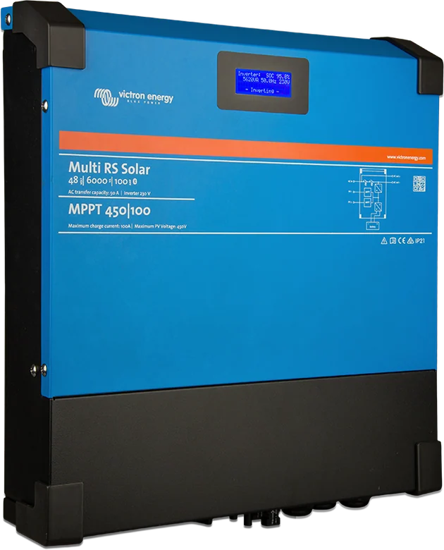
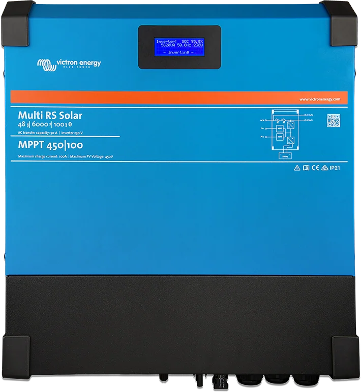
Multi RS Solar 48|6000 with MPPT 450|100 controller — front with display
One enclosure instead of three. The front display shows live values; the MPPT 450|100 designation refers to the panel voltage and total charge current.
Features

What the Multi RS Solar can do

Two 450 V MPPT trackers

Each tracker accepts a separate panel array: 12 A operating current, 16 A short-circuit current and 3 kW power — 6 kW in total. MPPT operation from 65 to 450 V, start from 120 V.

6 kVA inverter

230 V ± 2%, 25 A continuous. Continuous power at 25 °C from 4600 W (46 V DC) to 5200 W (52 V DC), 4500 W at 40 °C, 3000 W at 65 °C. Peak 9 kW for 3 s.

Charging from AC and PV

From AC input up to 88 A (5000 W at 230 V), and up to 100 A with panels. Absorption 57.6 V and float 55.2 V factory default, adjustment range 36–60 V.

AC input with PowerAssist

187–265 V, 45–65 Hz, pass-through up to 50 A. PowerControl limits the current drawn from the shore power or generator, PowerAssist adds the missing power from the battery.

Five operating modes

On, Off, Charger only, Inverter only (relays disconnect the grid — charging only from PV) and Pass through. Factory default ESS mode is “Keep batteries charged”, grid code “None”.

VE.Can, VE.Direct, Bluetooth

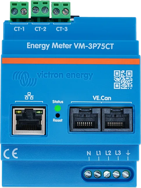
To the GX centre via VE.Can; also a programmable relay, two analogue/digital inputs and remote on/off. The only supported energy meter is VM-3P75CT.

Three-phase system

Three units, one per phase. Parallel operation of two units on one phase is not supported, and the Inverter RS does not connect with the Multi RS.

PV array monitoring

The unit checks insulation resistance (100 kΩ threshold before start) and leakage current (30 mA), and will not start if the insulation is too low.

Technical data

Main specifications

DC input (battery)38–62 V; starts at 41 V, disconnects on overvoltage at 65.5 V; low-voltage cut-out / reconnect at 37.2 / 43.6 V (adjustable)
AC output230 V ±2%, 50 Hz (240 V and 60 Hz possible); 25 A continuous
Continuous powerat 25 °C from 4,600 W (46 V DC) to 5,200 W (52 V DC) — linear; 4,500 W at 40 °C; 3,000 W at 65 °C
Peak power9 kW for 3 s, 7 kW for 4 min (for a cold unit)
No-load consumption20 W
AC input187–265 V, 45–65 Hz; transfer switch and passthrough up to 50 A; PowerControl and PowerAssist
Chargingup to 88 A from AC (5,000 W at 230 V), AC + PV total up to 100 A; absorption 57.6 V, float 55.2 V (factory default, adjustable 36–60 V)
PV2 trackers; Voc up to 450 V; starts at 120 V, MPPT operating range 65–450 V; per tracker: 12 A operating, 16 A short-circuit, 3 kW (6 kW total)
CommunicationVE.Can, VE.Direct, Bluetooth; programmable relay; 2 analogue/digital inputs; remote on/off
EnclosureIP21, class I; −40…+65 °C (fan); 462 × 425 × 127 mm; 12.3 kg; AC terminals 10 mm²; battery: M8 bolts

The datasheet and manual differ slightly (for example, continuous power at 52 V: 5,200 W in the datasheet, 5,300 W in one chapter of the manual; efficiency 96.5% in the datasheet, 96% in the general description). The discontinued model with one tracker (PMR482602000) had an MPPT rating of up to 4 kW — Victron’s official drawing BJE-333A refers to this model. We use the battery bank and protection devices from that drawing in the off-grid cabin diagram, built around a MultiPlus-II and a separate SmartSolar MPPT controller.

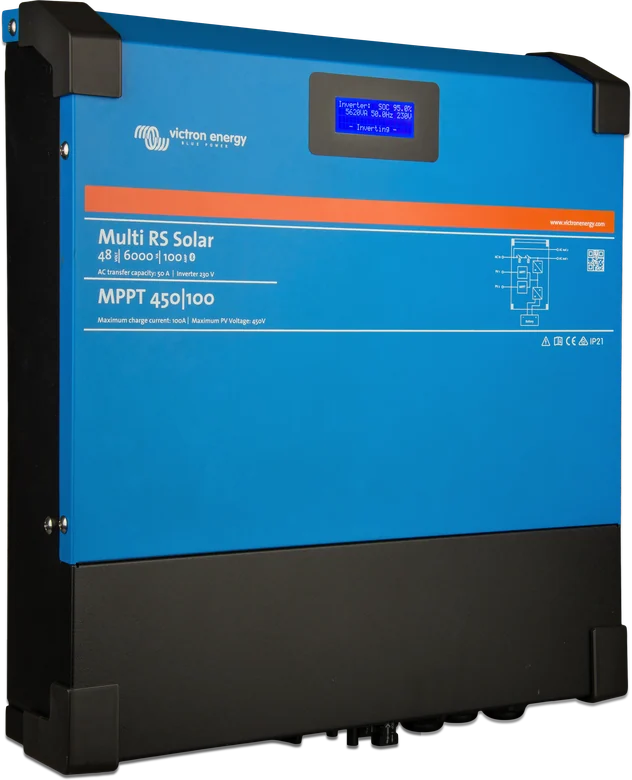
Multi RS Solar at an angle — slim enclosure with a black connection base
The unit referred to alongside this. Multi RS Solar at an angle — slim enclosure with a black connection base
Typical setup

Where Multi RS Solar sits in the system

Overview diagram of a 48 V system — off-grid cabin or grid-connected hybrid. Hover over or tap a diagram element to see its description.

AC-in AC-out-1 AC-out-2 fuse 2 PV inputs (MC4) VE.Can Grid / generator Multi RS Solar 230 V loads Non-critical 230 V 48 V battery PV panels Cerbo GX
direct current (DC) 230 V (AC) communication
Hover over or tap a diagram element.
  1. Mains / generator → AC-inExternal supply 187–265 V. Set the input current limit in Multi RS. Protect the input with a circuit breaker rated at no more than 50 A.
  2. Multi RS SolarPasses mains power to the loads and charges the battery, or produces 230 V from the battery. Two 450 V MPPT trackers are in the same enclosure.
  3. AC-out-1 → 230 V loadsAlways live — from mains or from the battery. 25 A continuous from the inverter. Protect the output with a circuit breaker rated at no more than 50 A.
  4. AC-out-2 → non-criticalHard-wired to the AC input. Only live when external power is present, to avoid discharging the battery.
  5. 48 V batteryOn the DC side, a fuse (125 A with 35 mm² or 200 A with 70 mm²) between the battery and the unit.
  6. PV panels → 2 PV inputs (separate strings, MC4)Two isolated trackers. Voc up to 450 V, no more than 8 × battery float voltage.
  7. Cerbo GX (VE.Can)The only path to the GX device. Terminators at the ends of the bus. Configuration in VictronConnect.
Panels

PV connection rules

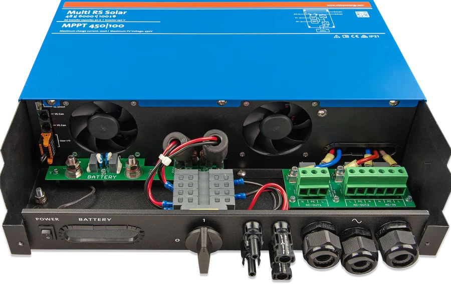
Multi RS Solar with the connection compartment open — fans, battery terminals, AC terminal blocks and PV inputs
Two PV inputs. The MC4 connectors of both trackers are in the base next to the battery terminals and AC rails — one panel array cannot feed both inputs.
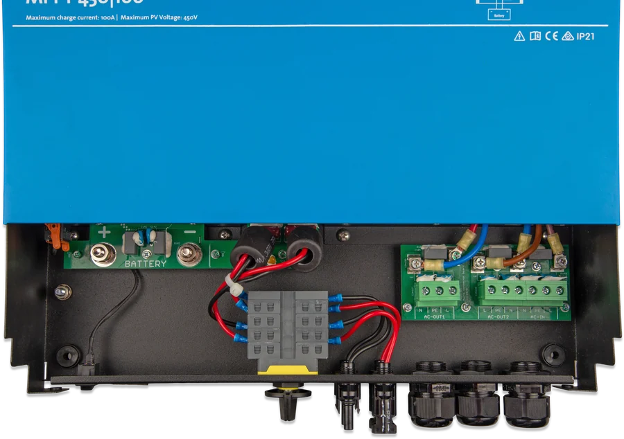
Multi RS Solar connection compartment — PV connectors, cable glands and AC terminals
Cable glands and terminals. The AC connections accept 10 mm² cable, the battery terminals are M8 bolts tightened to no more than 14 Nm.
Multi RS Solar at an angle — slim enclosure with a black connection base
IP21 enclosure. 462 × 425 × 127 mm and 12.3 kg — mount the unit vertically; it is fan-cooled.
  • The array Voc should not exceed 8 × battery float voltage (at 54 V float — 432 V), and under no circumstances 450 V. Open-circuit panel voltage (Voc) rises when temperature falls below 25 °C — by the percentage per degree stated by the Voc temperature coefficient in the panel datasheet. With Victron BlueSolar panels (−0.35%/°C), at −20 °C this is about 16% more than in the catalogue.
  • One PV array must not be connected to both trackers — the inputs must be isolated from each other.
  • Only original Stäubli MC4 connectors. The modules must be IEC 61730 Class A (inverter without PV–AC isolation). PV+ and PV− conductors must be isolated from earth; earth the panel frame in line with local requirements, and connect the enclosure earth terminal with a conductor of at least the same cross-section as the PV cables. Do not use panels with optimisers.
  • PV reverse polarity is not indicated: charging current is zero, the unit heats up, and PV voltage is close to zero. A reversely connected string with short-circuit current above 16 A voids the warranty.
  • The unit checks PV insulation (100 kΩ threshold before start-up) and leakage current (30 mA). If there is an insulation fault, do not touch metal parts; the system should be checked by a qualified technician. If insulation is too low, the inverter switches off the AC outputs while the MPPT continues to charge the battery.

Panel selection: guide and MPPT calculator.

Multi RS Solar on the right side
Panel inputs. Multi RS Solar on the right
Which model

Multi RS Solar, Inverter RS or EasySolar-II GX?

This sheet

Multi RS Solar

An inverter, an AC charger and two 450 V MPPT trackers in one enclosure. Choose it when you have panels and also want to charge from mains or a generator.

2 × MPPT 450 V + 88 A charger
No AC charger

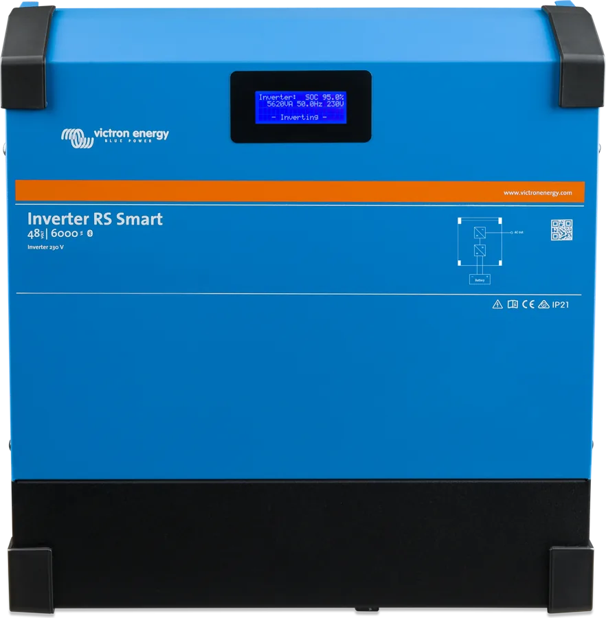
Inverter RS Smart

A standalone 48 V inverter (the Solar version has one MPPT 450|80 controller). It charges the battery from panels or from an external PV inverter on the AC output — not from mains. Inverter RS Smart datasheet.

inverter + PV, no AC input
With built-in GX

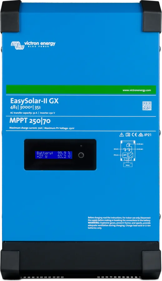
EasySolar-II GX

MultiPlus-II, SmartSolar controller and GX device with display factory-connected — if you want a ready-made system with a control panel. EasySolar-II GX datasheet.

MultiPlus-II + MPPT + GX

This family also has a rack version — Multi RS19 Solar — and a version without built-in MPPTs — Multi RS. The three-phase equivalent with a high-voltage battery is Multi HS19 Solar.

Installation

Installation rules

400–500 V DC inside

The unit may contain 400–500 V DC even when switched off. Before any work, disconnect all power sources and wait at least 5 minutes. The enclosure must be earthed (class I); grid systems only TN and TT.

  • Sequence: first the battery (after checking polarity), then the control and communication cables, and finally the panels.
  • DC cables: at least 35 mm² for 0–2 m and 70 mm² for 2–5 m; fuse 125 A for 35 mm², 200 A for 70 mm². Flexible copper cables, strand diameter up to 0.4 mm. Battery terminal nuts tightened to no more than 14 Nm — do not undo the lower nut (it is soldered to the PCB). Do not connect a battery without protection.
  • Minimum battery: 200 Ah lead-acid or 100 Ah lithium, but check the battery manufacturer’s documentation to confirm it can accept the system’s total charge current; agree the capacity with the system designer. A voltage drop on the battery cables above 2.5% is not acceptable (Vsense compensation will equalise up to 1 V per terminal).
  • AC: insulation stripped by 10 mm, terminals tightened to no more than 1.2 Nm; do not swap L and N. Protect the AC input and output with a circuit breaker rated at no more than 50 A; for the AC input, if the source has a lower rating, choose a smaller breaker appropriate to that source. AC-out-2 is permanently connected to the input (uncontrolled) — intended for non-critical loads.
  • Vertical installation on a non-combustible surface, with 30 cm of free space above and below; not above lead-acid batteries. Do not install where exposed to water, rain, humidity, direct sunlight, dust/salt/soot, or flammable or corrosive gases; for the installation location the manufacturer specifies −40…+60 °C and humidity <95% non-condensing. The programmable relay is not intended for 230 V circuits (contacts 4 A at 35 V DC, 1 A at 70 V DC).
Multi RS Solar with the connection compartment open — fans, battery terminals, AC terminal blocks and PV inputs
The cables enter here. Multi RS Solar with the connection compartment open — fans, battery terminals, AC terminals and PV inputs
Modes and settings

How to set it up

  • Modes in VictronConnect: On, Off, Charger only (inverter off), Inverter only (AC input relays disconnect the grid — charging from PV only), Pass through.
  • By default, ESS is in “Keep batteries charged” mode and grid code “None” — without a grid code, feeding into the grid is impossible. For off-grid use and operation without feeding into the grid or generator: leave “Keep batteries charged”. The presence of a grid code in the list does not mean the system is certified in a given country.
  • Generator (software from v1.11): set input type to “Generator”, enable “Moderate generator load changes”, disable “Energy meter support”, set the input current limit to the generator power, and disable the UPS function. If a grid code is set, LOM may only be disabled for a generator, and set “Feed-in allowed” to off.
  • Victron LiFePO4 batteries require a compatible Victron BMS: Lynx Smart BMS NG via VE.Can and, at start-up, Remote Mode = “Remote on/off” in VictronConnect, or smallBMS NG via the I/O inputs (Remote terminal mode “2-wire BMS”: H = discharge allowed, L = charge allowed). Low-temperature charge lockout for LiFePO4 batteries: 5 °C. Batteries with a third-party BMS-Can are connected to the GX device BMS-Can port, not to the Multi RS.
  • GX device — only via VE.Can (not VE.Direct), with terminators at both ends of the bus. Energy meter: only Victron VM-3P75CT is supported (VE.Can or Ethernet; over Ethernet it requires Multi RS software from 1.26 and GX from 3.65; avoid Wi-Fi).
  • Three phases (software from v1.13): three devices, one per phase, star configuration with neutral; delta and split-phase are not supported. In a three-phase system the UPS function can be too sensitive — disable it if the AC input disconnects often. Do not enable “Continue with missing phase” if you have three-phase loads (for example, motors).
  • Temperature compensation: if in doubt, −64.80 mV/°C for lead-acid batteries, disabled for lithium batteries.
Multi RS Solar 48|6000 with MPPT 450|100 controller — front with display
Select the mode here. Multi RS Solar 48|6000 with MPPT 450|100 controller — front with display
Limitations

What Multi RS Solar does not do

  • It does not run in parallel with another device (three phases only, one per phase). Inverter RS does not connect with Multi RS.
  • It does not support VEConfigure Assistants or the VE.Smart network.
  • Full ESS is not yet available in all installations (not all grid codes are supported); the discontinued model with a single tracker does not feed into the grid in ESS.
  • With an external PV inverter on the AC output (max. 5000 W), Multi RS Solar controls power by frequency shifting only when its AC input is disconnected; the f stop is 53.2 Hz. This arrangement charges the battery only to about 95%, not 100%. Total charge current is still limited to 100 A.
Multi RS Solar 48|6000 with MPPT 450|100 controller — front with display
The device referred to beside it. Multi RS Solar 48|6000 with MPPT 450|100 controller — front with display
Errors

Error codes

The codes appear on the display and in the VictronConnect app, and via VE.Can they are sent to the GX device and the VRM portal. Below are selected codes from the Multi RS Solar manual — the full list is in the manufacturer’s documentation.

Error 2

Battery voltage too high

The DC terminal voltage has exceeded the permitted level.

Clears automaticallyonce the voltage drops.
Error 11

Excessive DC ripple

The ripple at the battery terminals is too high — usually loose connections or DC cables that are too small.

Error 29

Over-Charge protection

The device stops charging to avoid overcharging the battery.

Clears automaticallyafter the voltage drops below float.

Error 33

PV overvoltage

The PV array voltage has exceeded the permitted value. Calculate the string Voc with a margin for frost — it must not exceed 450 V.

Error 41

PV insulation resistance too low

Before start-up, the device checks the insulation of the PV array (threshold 100 kΩ). Check the panel wiring and connections.

Error 42

PV leakage current above 30 mA

Leakage has been detected on the panel side — the device stops operating until the cause is cleared.

Error 43

N–PE voltage difference too high

Most often the L and N conductors are swapped, or the installation is not earthed.

Error 50, 52

Overload or peak current

After three restarts the device shuts down — disconnect the load, switch it off and on again.

Does not clear automaticallyafter three attempts.

Error 51

Overtemperature

The inverter stops operating and restarts after 30 seconds. Provide a cool, ventilated location.

Clears automaticallyafter 30 s.

Error 57

AC output voltage before start-up

There is voltage on AC-out from another source. The AC outputs must not be connected to the grid or to another inverter.

Error 67

Lost connection with BMS

The device is not receiving messages from the battery BMS and stops charging. Check the VE.Can connection to the BMS.

Error 69, 71

Incompatible configuration on the CAN bus

The units have different configurations or different software versions — update all of them to the same version.

Error 72

Incorrect phase order

In a three-phase system the phases are connected in the wrong order.

Error 74, 76

Incorrect number of devices in the system

In a multi-phase system there are too many or too few units compared with the configuration.

Error 119

Settings lost

The device cannot read the configuration. Restore factory settings, disconnect power for 3 minutes, and configure it again.

Does not clear itself

Questions

Frequently asked questions about Multi RS Solar

Will Multi RS Solar work without a battery, as a PV inverter?

Only in a grid-connected system, with the grid code set and the required approvals. In off-grid operation, a battery is required.

How many panels can be connected?

The device has two independent MPPT trackers up to 450 V. PV array details — permissible current, number of strings and frost margin — are in the “Panels” section on this page.

What cables and fuse on the battery side?

At least 35 mm² for a length of 0–2 m and 70 mm² for 2–5 m, with a 125 A fuse for 35 mm² and 200 A for 70 mm². The battery terminal nuts are tightened to a maximum of 14 Nm; the lower nut must not be loosened.

How do you prepare the device for use with a generator?

From software version v1.11: set the input type to “Generator”, enable “Moderate generator load changes”, disable “Energy meter support”, set the input current limit to the generator power, and disable the UPS function.

Why do you need to wait 5 minutes before working on it?

The device can still contain 400–500 V DC even after switch-off. Before opening it, disconnect all power sources and wait at least 5 minutes.

Content checked against Victron Energy documentation (datasheets and manuals) — as of 19 September 2026. Report a content error · Revision log