
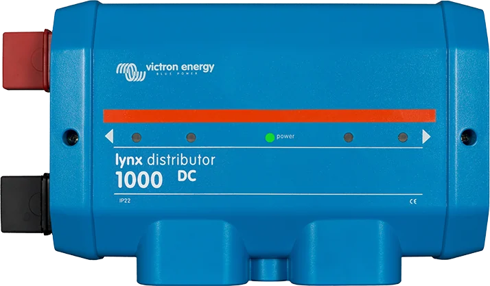
Lynx Distributor 1000 — distribution module with fuse status LEDs
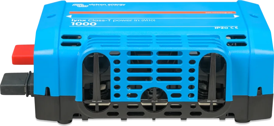
Lynx Distributor, Power In and Class-T Power In
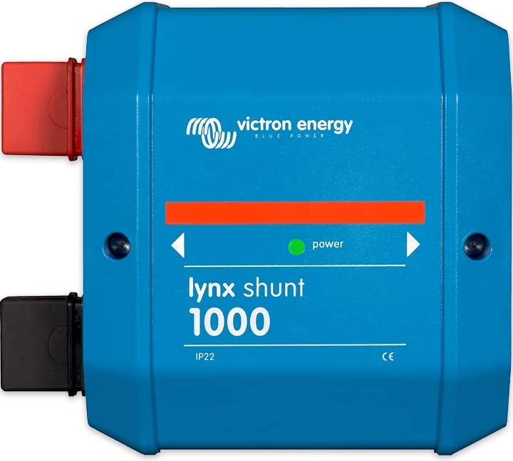
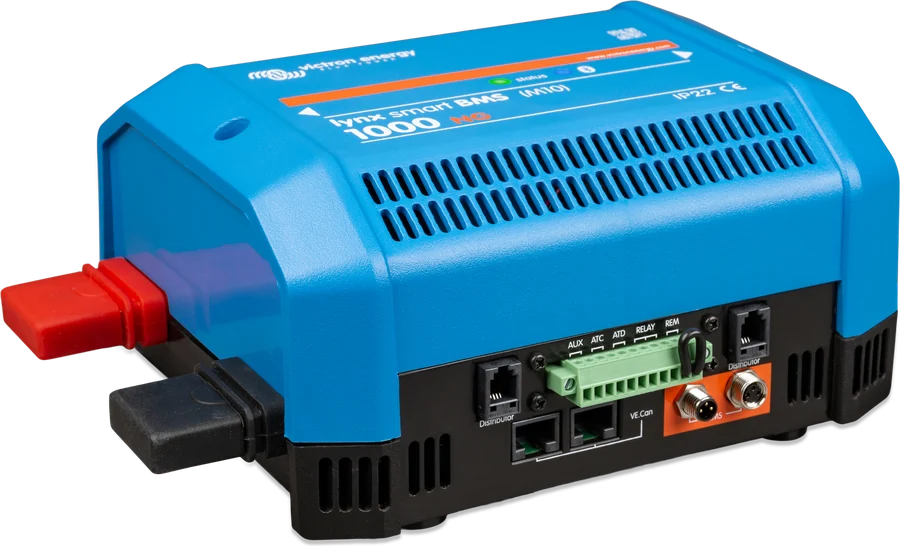
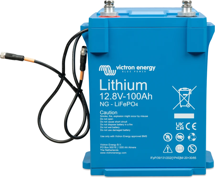
Victron Lynx modular DC busbar system: the modules bolt together into a single positive and negative busbar to which batteries, inverters, chargers and loads are connected. Together with Lynx Smart BMS or Lynx Shunt VE.Can they form a complete, monitored energy distribution system — without a tangle of wires and separate fuse holders.
- 1000 A continuous
- 12 / 24 / 48 V
- M8 or M10
- MEGA fuses or Class-T
Three modules, one busbar
| Lynx Distributor | Lynx Power In | Lynx Class-T Power In | |
|---|---|---|---|
| What it is for | section: 4 circuits with MEGA fuses (sold separately) and monitoring of each fuse | connection: 4 positions for batteries, loads or chargers, without fuses (external protection) | connection and protection for up to two lithium battery strings with Class-T fuses |
| Busbars between modules | M8 or M10 | M8 or M10 | M10 |
| Cables | M8 terminals | M8 terminals | M10 terminals, up to 120 mm²; fuses secured with 3/8" nuts |
| Dimensions, weight | 290 × 170 × 80 mm, 2.2 kg | 290 × 170 × 80 mm, 2.1 kg | 279 × 169 × 97 mm, 2.1 kg |
| Ingress protection | IP22 | IP22 | IP20 |
- All: 9–60 V DC (12, 24, 48 V systems), 1,000 A continuous, 8 × 30 mm tinned copper busbar, operating temperature from −40 to +60 °C.
- M8 and M10 modules are not connected directly to each other. “M10” refers to the busbar connections between modules — the fuses and cables in the Lynx Distributor are always M8.
- The sum of the fuse currents of all circuits must not exceed the module’s rated current — and, in a multi-module set, the rated current of the weakest module (for example, Lynx Smart BMS 500 A). In one Class-T Power In, a maximum of 800 A (2 × 400 A), and 1,000 A in total; for three or more battery strings — several Class-T modules.
- The Power In and Distributor modules also work without Lynx Smart BMS and Lynx Shunt if monitoring is not needed — but then the Distributor LEDs do not work (the electronics are powered by the RJ10 cable from the BMS or Shunt).
Example of a complete system with Lynx Class-T Power In, Lynx Smart BMS NG and Lynx Distributor: boat diagram.
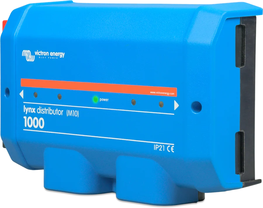
What a Lynx system with Distributor looks like
Lynx modules are bolted together into one positive and negative busbar. In the normal orientation, the batteries are on the left and the loads and chargers on the right. The red busbar is positive, the black one is negative. Concept diagram.
- Modules into one busbarTorqued to 14 Nm (M8) or 33 Nm (M10); M8 and M10 modules are not connected to each other.
- Batteries on the leftLoads and chargers on the right; the red busbar is positive, the black one is negative.
- MEGA fuses36 V for 12 and 24 V, 58 V for 48 V; all four fuse holders fitted.
- MonitoringThe RJ10 cable sends fuse status to the Lynx Smart BMS or Lynx Shunt.
- Sum of currentsThe sum of the fuses must not exceed the current rating of the weakest module in the set.
Order, torques, fuses
| Connection | Torque |
|---|---|
| Between modules, M8 | 14 Nm |
| Between modules, M10 | 33 Nm (units before serial number HQ2340… — 17 Nm) |
| Lower nuts of the centre row in the Distributor, before fitting the fuses | 10 Nm |
In the troubleshooting section, the Distributor manual instructs you, if the cables are heating up, to check the 14 Nm tightening torque (17 Nm for M10) — this is a different value from the 10 Nm in the fuse installation description. If in doubt, follow the installation section of the manual for your model.
- Never work on live busbars. Work on batteries is for qualified personnel only, following the warnings in the battery manual. Before removing the cover and before connecting positives, disconnect all positive battery cables.
- With Lynx Smart BMS or Lynx Shunt: batteries on the left, loads and chargers on the right. The red busbar is positive, the black one is negative.
- MEGA fuses: 36 V for 12 and 24 V systems, 58 V for 48 V. Fit all four — use dummy fuses in unused circuits, otherwise the red LED lights.
- Class-T Power In: tighten cable, busbar and fuse connections to 33 Nm. Secure the fuses with black 3/8" nuts (confusing them with M10 can damage the thread); if the fuse flanges do not sit flat on the busbar, rotate it 180°. Why Class-T for lithium batteries: breaking capacity.
- One earthing point in the system, behind the Lynx Smart BMS, Lynx Shunt or battery monitor shunt. Leave the red wire with the terminal at the Distributor earth terminal in place.
- The RJ10 connector is not reverse-polarity protected — a mistake can permanently damage the electronics. For cables thicker than 10 mm, remove the separator post.
- The modules can be mounted in any orientation (stickers are provided for upside-down mounting); fixing through 5 mm holes.
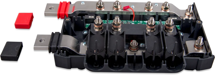
Several Distributors with Lynx Smart BMS
Up to four Distributors can be connected to the Lynx Smart BMS (RJ10 cable, 40 cm included — power and fuse data are carried through it). Each one is given an address with two DIP switches:
| Address | DIP 1 | DIP 2 |
|---|---|---|
| A (factory default) | off | off |
| B | on | off |
| C | off | on |
| D | on | on |
Assign addresses from left to right so the alarms match the physical position. In VictronConnect you can name each fuse (up to 16 characters); a fuse with an empty name is not monitored. Communication requires a Distributor from serial number HQ1909 and works only with Lynx Smart BMS — with Lynx Shunt VE.Can, the Distributor does not send fuse status. When the Lynx Smart BMS is connected to a GX device via VE.Can, the GX shows the status of each fuse, and if the GX is connected to the internet — also in VRM.
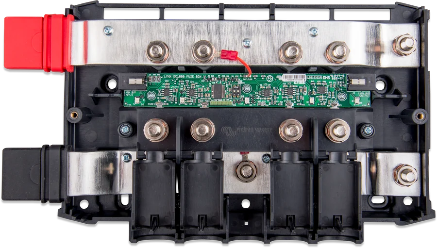
What the Distributor shows
| Diodes | Meaning |
|---|---|
| power green, fuses off | normal operation |
| power and fuse LED red | fuse blown, missing, faulty or loose (blown = voltage drop above 0.5 V, good below 0.3 V) |
| power yellow | no voltage on the positive busbar (power is present via RJ10) |
| all off | no power to the electronics via RJ10 from Lynx Smart BMS or Lynx Shunt |
| at start-up: all for 1 s, then fuse LED 1–4 | address A–D (units before serial number HQ1909 show only all LEDs for 1 s) |
Alarm codes in Lynx Smart BMS: blown fuse — #201–#216 (Distributor A–D, fuse 1–4), communication loss — #221–#224 (usually a disconnected RJ10 cable). A battery fuse blowing in a multi-circuit system may only be detected during charging or discharging, and Distributors before HQ1909 will not detect a blown fuse at all when batteries are connected. See also Lynx Smart BMS codes.
Lynx Distributor FAQs
How do the Lynx modules differ?
Lynx Distributor splits four circuits and protects them with monitored MEGA fuses. Lynx Power In provides four fused connections. Lynx Class-T Power In connects and protects up to two lithium battery strings with Class-T fuses.
Which MEGA fuses should I buy?
For 36 V systems in 12 and 24 V systems, and 58 V for 48 V. Fit all four — use dummy fuses in unused circuits, otherwise the red LED will light.
Can I mix an M8 module with an M10 module?
No. M8 and M10 modules are not connected directly to each other. The designation refers to the inter-module busbar connections — the fuses and cables in Lynx Distributor are always M8.
How much current can the set carry?
Each module carries 1,000 A continuously, but the total fuse current of all circuits must not exceed the rated current of the weakest module in the set — for example 500 A with Lynx Smart BMS.
Does Distributor work without Lynx Smart BMS?
Yes, the Power In and Distributor modules also work on their own if monitoring is not needed.
Content checked against Victron Energy documentation (datasheets and manuals) — as of 19 September 2026. Report a content error · Revision log