
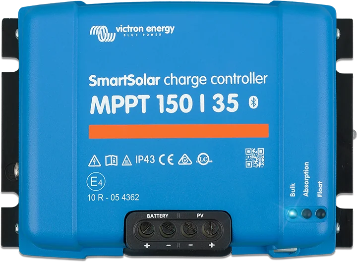
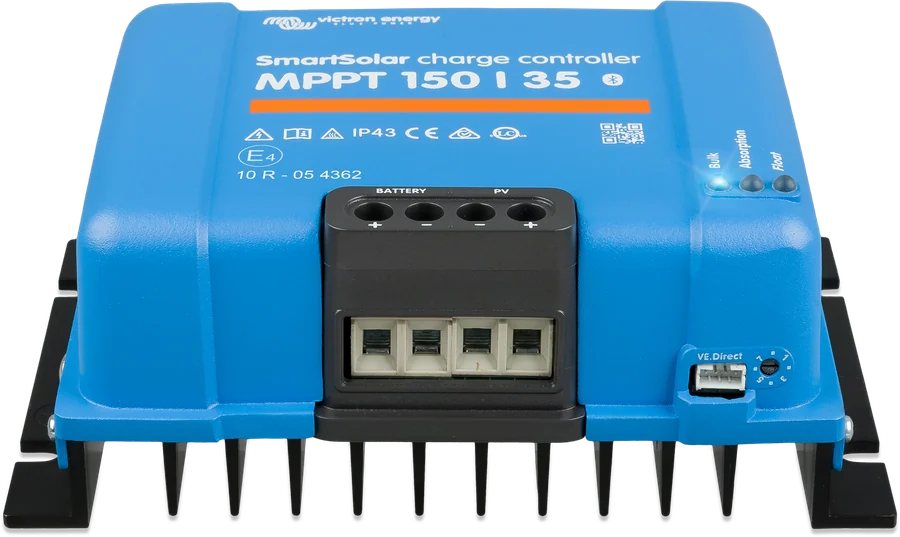
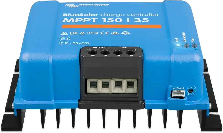
SmartSolar MPPT 150|35 — top view with BATTERY and PV terminals
SmartSolar MPPT 150 V and 250 V
Larger Victron solar controllers: 35 to 100 A charge current, for panels connected in series into longer strings. They charge 12, 24 and 48 V batteries (36 V after manual setting; except for the specified 150/85 and 150/100 VE.Can variants marked 12/24 V only). They usually have Bluetooth (the 150/100 VE.Can also comes in a version without Bluetooth) and a 46-day history.
- 150 V or 250 V from the panels
- 35–100 A
- 12/24/36/48 V (with exceptions 12/24 V only)
- Bluetooth (150/100 VE.Can also without)
- VE.Direct or VE.Can
Controller for long panel strings
This series does the same as the smaller SmartSolar controllers — it tracks the panel’s maximum power point and charges the battery from it — but accepts much higher array voltage: 150 V or 250 V. This lets you connect panels in series into longer strings, use thinner cables and lose less on the way from the roof to the battery.
Charge current ranges from 35 to 100 A, and batteries can be 12, 24, 36 or 48 V. Versions differ in panel connection (Tr screw terminals or MC4 connectors) and communication — VE.Can models connect to the GX device and to each other.
- 98–99% efficiency and 46-day yield history in the app,
- charging starts when panel voltage exceeds battery voltage by 5 V,
- several controllers can be synchronised: up to 10 via Bluetooth, up to 25 via VE.Can.
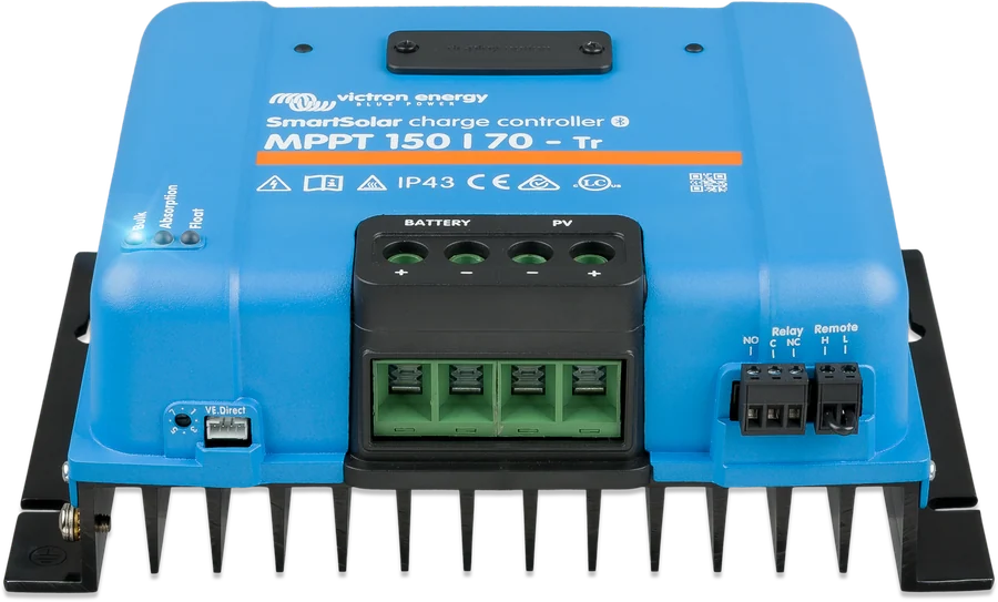
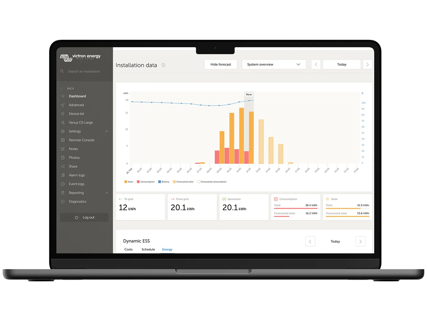
What the SmartSolar MPPT 150 V and 250 V can do
High array voltage
The 150 V series operates and starts up to 145 V (150 V is the absolute maximum in the coldest conditions), while the 250 V series does so up to 245 and 250 V respectively.
Charge current 35–100 A
Efficiency 98–99%. The controller runs at full current up to 40 °C, and reduces power above that temperature.
12–48 V batteries
12, 24 and 48 V automatically, 36 V after manual setting. The exceptions are the 150/85 and 150/100 VE.Can variants marked “12/24 V only”. Factory absorption 14.4 V and float 13.8 V at 12 V (×2, ×3, ×4 for higher voltages).
Three connector types
Tr — screw terminals for PV cables up to 35 mm². MC4 — pairs of MC4 connectors, up to 30 A per connector, so splitters may be needed with several strings. VE.Can — additional bus port.
Bluetooth and history
Settings and monitoring in the VictronConnect app, with a 46-day history. The 150/100 VE.Can model also comes in a version without Bluetooth.
Group operation
The 60 and 70 A controllers synchronise charging over Bluetooth (up to 10 units), and the VE.Can versions over the bus (up to 25). Each needs its own panel array and its own fuse near the battery.
VE.Direct or VE.Can
To the GX device and the VRM portal, and in lithium battery installations — control via remote on/off (for example from a VE.Bus BMS) or via the GX device and DVCC.
Protections
Protection against reverse polarity and reverse current on the panel side. Voltages above 50 V DC are regarded as dangerous — installation should be carried out by a qualified technician.
When small 75/100 V controllers are not enough
SmartSolar 75/100 V
Up to 20 A and 100 V from the panels — enough in a campervan and with short strings. SmartSolar 75–100 V datasheet, and for 30 and 50 A 100/30 and 100/50.
up to 20 A · 100 VSmartSolar 150 V and 250 V
35–100 A and longer panel strings. Tr, MC4 and VE.Can versions, 12–48 V batteries. The most common choice for a cabin or building roof.
35–100 A · 150/250 VSmartSolar MPPT RS 450
Up to 450 V from the panels with a 48 V battery — when strings are really long or the array is large. MPPT RS 450 datasheet.
up to 450 V · 48 VThe smaller SmartSolar 75/10–100/20 units top out at 20 A and 100 V from the panels. The larger series is useful when:
- there are more panels — for example 800 W with a 12 V battery needs a controller of around 50–70 A,
- you want to connect panels in series — three panels with Voc 37 V give about 128 V in frost, so you need a 150 V controller (example in MPPT selection),
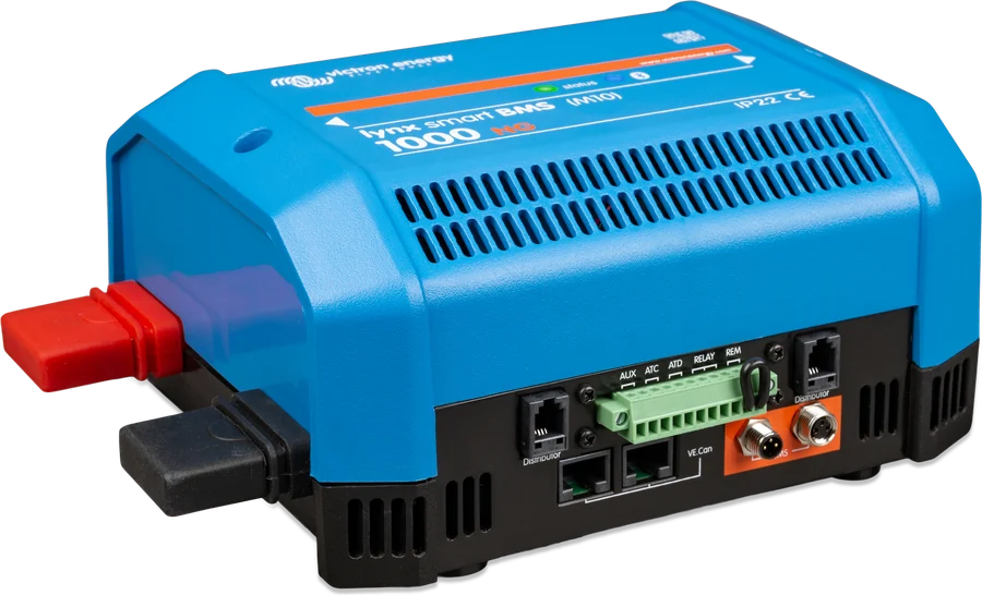
- the system is larger — VE.Can versions connect to the GX device and to each other via VE.Can (up to 25 controllers), which makes installations with Lynx Smart BMS easier.
For very long strings with a 48 V battery there is also the SmartSolar MPPT RS 450 (up to 450 V).
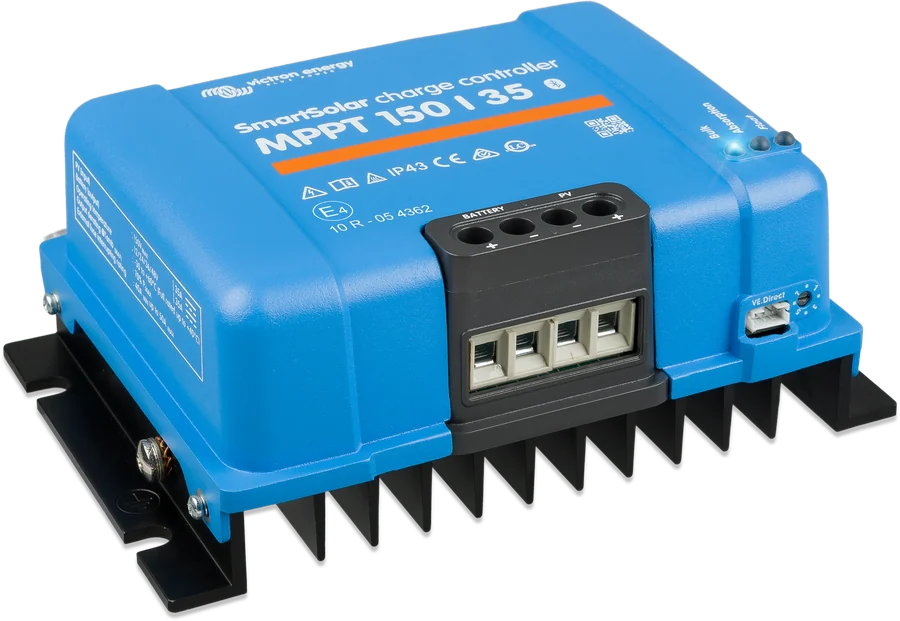
Model comparison
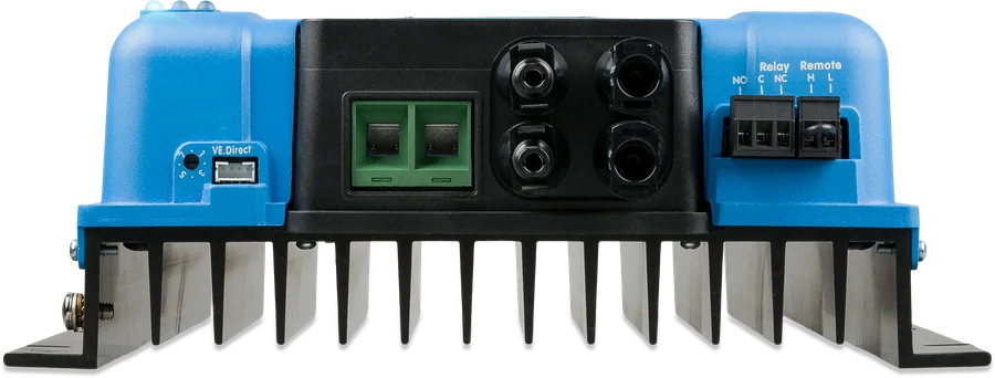
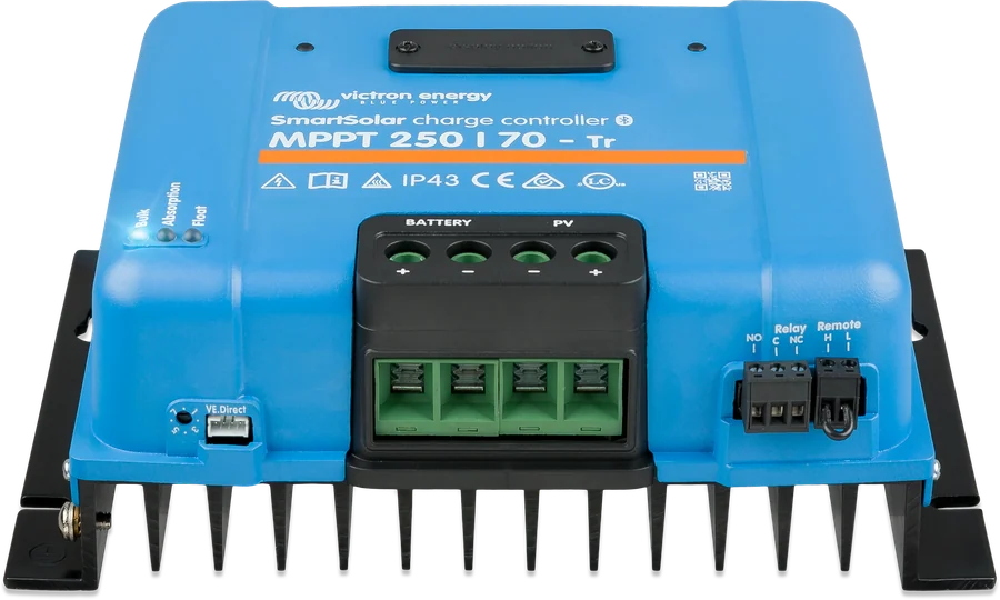
| Model | Charge current | Max. panel Isc | Panel power at 12 V | 24 V | 48 V | PV connections |
|---|---|---|---|---|---|---|
| 150/35 | 35 A | 40 A | 500 W | 1000 W | 2000 W | 16 mm² terminals |
| 150/45 | 45 A | 50 A | 650 W | 1300 W | 2600 W | 16 mm² terminals |
| 150/60 | 60 A | 50 A | 860 W | 1720 W | 3440 W | Tr (35 mm²) or MC4 |
| 150/70 | 70 A | 50 A | 1000 W | 2000 W | 4000 W | Tr or MC4; also VE.Can |
| 150/85 VE.Can | 85 A | 70 A | 1200 W | 2400 W | 4900 W | Tr or MC4 |
| 150/100 VE.Can | 100 A | 70 A | 1450 W | 2900 W | 5800 W | Tr or MC4 |
| 250/60 | 60 A | 35 A | 860 W | 1720 W | 3440 W | Tr or MC4 |
| 250/70 | 70 A | 35 A | 1000 W | 2000 W | 4000 W | Tr or MC4; also VE.Can |
| 250/85 VE.Can | 85 A | 70 A | 1200 W | 2400 W | 4900 W | Tr or MC4 |
| 250/100 VE.Can | 100 A | 70 A | 1450 W | 2900 W | 5800 W | Tr or MC4 |
Nominal power at 36 V: 150/35 — 1,500 W, 150/45 — 1,950 W, 60/70 A models — 2,580/3,000 W, 85/100 A — 3,600/4,350 W. You can connect more panels — the solar charge controller will limit the input power. A string with a higher short-circuit current than stated may damage the controller. On MC4 versions, max. 30 A per MC4 connector (the connectors are connected in parallel to one tracker).
| Feature | 150/35, 150/45 | 60–70 A (without VE.Can) | VE.Can 70–100 A |
|---|---|---|---|
| Communication | Bluetooth, VE.Direct | Bluetooth, VE.Direct | Bluetooth (150/100 VE.Can also available without Bluetooth), VE.Direct, VE.Can |
| Parallel operation (synchronisation) | up to 10 units via VE.Smart Networking/Bluetooth | up to 10 units via Bluetooth | up to 25 units via VE.Can or 10 via Bluetooth |
| Remote on/off, programmable relay | virtual remote via VE.Direct (optional cable); relay — | yes (DC relay: 4 A up to 35 V, 1 A up to 60 V) | yes |
| Display | — | optional, plug-in | optional, plug-in |
| Weight, dimensions (H × W × D) | 1.25 kg, 130 × 186 × 70 mm | 3 kg; Tr 185 × 250 × 95 mm, MC4 215 × 250 × 95 mm | 70 A: 3 kg; 85/100 A: 4.5 kg (Tr 216 × 295 × 103 mm) |
| Self-consumption | 20 / 15 / 10 mA (12/24/48 V) | below 35 mA at 12 V, 20 mA at 48 V | |
Common: operating temperature −30…+60 °C (full current up to 40 °C), IP43 electronics / IP22 connections, temperature compensation −16 mV/°C for 12 V, 8 built-in charging algorithms selected by rotary switch or a custom algorithm.
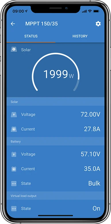
Two limits: 145 V and 150 V (245 V and 250 V)
The datasheet gives two values for the 150 V series: 150 V is the absolute maximum in the coldest conditions, while 145 V is the maximum start and operating voltage. For the 250 V series: 250 V and 245 V. If Voc in frost exceeds the start voltage, the controller may not start on the coldest mornings until the panel voltage drops.
Warning: DC voltages above 50 V are generally considered hazardous; only a qualified technician should work on them.
The open-circuit panel voltage (Voc) rises when the temperature falls below 25 °C — by the percentage per degree given by the Voc temperature coefficient in the panel datasheet. For Victron BlueSolar panels (−0.35%/°C), at −20 °C this is about 16% more than in the catalogue. Victron recommends leaving at least 10% voltage headroom and, in a cold climate, recalculating Voc for the lowest expected temperature. Work it out in the MPPT calculator — it covers both limits.
The controller starts charging when the panel voltage exceeds the battery voltage by 5 V, and continues charging while the panel voltage remains at least 1 V higher.
How to connect SmartSolar MPPT 150 V and 250 V
Larger controllers work with longer panel strings. The order stays the same: battery, 10 s to detect voltage, then PV. Simplified diagram.
- Battery firstAfter 10 s, check the detected system voltage.
- PanelsVoc with frost headroom below 150 or 250 V; panel frames earthed.
- Fuse and cablesAccording to the model table; terminals 16 or 35 mm².
- Lithium batteryControl via remote on/off or GX with DVCC.
- MonitoringBluetooth, VE.Direct or VE.Can on models with this port.
Fuses, cables, torques
| Model | Battery fuse min. | max. | Tightening torque |
|---|---|---|---|
| 150/35 | 40 A | 45 A | 1.6 Nm |
| 150/45 | 50 A | 63 A | |
| 150/60, 250/60 | 70 A | 80 A | 2.4 Nm |
| 150/70, 250/70 (also VE.Can) | 80 A | 100 A | |
| 150/85, 250/85 VE.Can | 100 A | 120 A | |
| 150/100, 250/100 VE.Can | 120 A | 140 A |
- Flexible copper stranded cables: single wire diameter no more than 0.4 mm (0.125 mm²), e.g. a 25 mm² cable with at least 196 strands (Class 5); cable operating temperature up to 90 °C. Terminals: 16 mm² on 150/35–45, 35 mm² on the others.
- First connect the battery and wait 10 s for automatic voltage detection, then check the system voltage, then connect PV, and finally the remaining connections. You may connect PV first only if the system voltage was set manually before connecting the battery.
- Do not use panels with optimisers — they may permanently damage the controller.
- Do not earth the positive or negative of the PV array; earth the panel frames. Make only one system-to-earth connection at the battery, and where regulations require it, use an external GFDI.
- The controller has reverse-polarity and reverse-current protection on the PV side.
- With a lithium battery and BMS: control via remote on/off (e.g. VE.Bus BMS) or via a GX device (DVCC).
More on cables and fuses: cable cross-sections and DC fuses. When the controller is not charging: MPPT troubleshooting and error codes.
Frequently asked questions
What is the difference between Tr, MC4 and VE.Can versions?
Tr has screw terminals for PV cables (35 mm²), MC4 has pairs of MC4 connectors (max. 30 A per connector, so splitters may be needed with several strings). VE.Can adds a VE.Can port: connection of up to 25 controllers and communication with a GX device via VE.Can.
Is the 250 V controller useful in a campervan?
Usually not — in a vehicle, panel strings are short and 100 or 150 V is enough. The 250 V version makes sense with longer strings, for example on a cabin or building. The 60/70 A models in this version have a lower maximum panel short-circuit current (35 A instead of 50 A).
Can I connect several controllers together?
Yes. The 60/70 A controllers synchronise charging via Bluetooth (up to 10 units), and the VE.Can versions via VE.Can (up to 25) or Bluetooth (up to 10). Each controller needs its own panel array and its own battery-side fuse.
What charging voltages are set at the factory?
Absorption 14.4 V and float 13.8 V at 12 V (×2, ×3, ×4 respectively for 24, 36, 48 V). For a lithium battery, choose the lithium profile or set the values from the battery manual — for Victron Lithium Smart 14.2 V and 13.5 V (12.8 V).
How much panel power should I connect to a given model?
Charging current and battery voltage are decisive — the nominal power for each model is given in the table above. The array may be larger than nominal: the controller will then limit the input power. However, you must not exceed the permitted voltage or panel short-circuit current.
In what order should I connect the cables?
First the battery and a 10-second pause for automatic voltage detection, then check the system voltage, then the panels, and finally the remaining connections. You may connect the panels first only if the system voltage was set manually beforehand.
What battery fuse?
Depending on the model: 40–45 A for 150/35, 50–63 A for 150/45, 70–80 A for 60 A, 80–100 A for 70 A, 100–120 A for 85 A and 120–140 A for 100 A. Tightening torque is 1.6 Nm on the 35 and 45 A models and 2.4 Nm on the others.
Why does the controller not start in the morning even though the sun is shining?
If the panel voltage in frost exceeds the maximum start voltage (145 V for the 150 V series, 245 V for the 250 V series), the controller will wait until the voltage drops. That is why you size the string with headroom — calculate it in the MPPT calculator.
Can I use panels with optimisers?
No — according to the manual, they may permanently damage the controller. You must also not earth the positive or negative of the panel array; earth the module frames, and the whole system must have one earth connection at the battery.

Manufacturer documentation
- SmartSolar MPPT 150/35 and 150/45 — product page, datasheet and manualvictronenergy.com · EN
- SmartSolar MPPT 150/60 and 150/70 datasheetvictronenergy.com · PDF · EN
- SmartSolar MPPT 250/60 and 250/70 datasheetvictronenergy.com · PDF · EN
- SmartSolar MPPT VE.Can 150/70 to 250/100 — product page, datasheets and manualvictronenergy.com · EN
Content checked against Victron Energy documentation (datasheets and manuals) — as of 19 September 2026. Report a content error · Revision log