
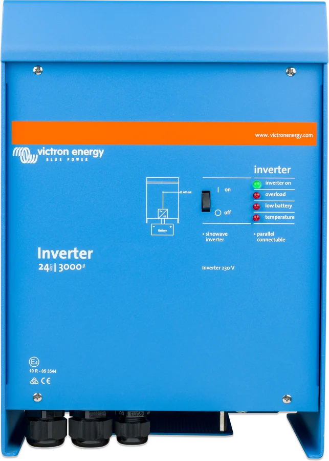
Phoenix Inverter 24|3000 — front with LED panel and switch
Phoenix Inverter 1200–5000 VA
Classic Victron sinewave inverter with VE.Bus port: the Compact 1200, 1600 and 2000 VA series for 12 and 24 V, plus 3000 VA models (12/24/48 V) and 5000 VA models (24/48 V). SinusMax technology provides high starting power, and via VE.Bus the inverters can be connected in parallel and in a three-phase system.
- 12 / 24 / 48 V
- 1200–5000 VA
- 230 V · 50 Hz
- VE.Bus
- IP21
Pure 230 V sine wave from the battery
Phoenix Inverter converts 12, 24 or 48 V battery voltage into a pure 230 V sine wave. The manufacturer describes it as an inverter for professional applications: hybrid HF technology gives small size and weight, while SinusMax provides very high starting power, allowing the inverter to start demanding loads such as fridge compressors and electric motors.
The VE.Bus port lets you connect up to six identical inverters in parallel or build a three-phase system (star only), and connect a panel, GX device or computer to change settings.
- Compact 1200, 1600 and 2000 VA series for 12 and 24 V,
- 3000 VA models (12, 24, 48 V) and 5000 VA models (24, 48 V),
- without a charger and without a source transfer switch — for that there is MultiPlus or Quattro.

What the Phoenix Inverter can do
SinusMax — starting power
Peak 2,400 W (1,200 VA) to 10,000 W (5,000 VA). The manufacturer emphasises that conventional HF technology cannot provide such reserve power.
Parallel and three-phase
Up to six identical inverters in parallel — six 24/5000 units give, according to the datasheet, 24 kW / 30 kVA. Three-phase system only in star (Y); delta is not supported; Compact also allows split-phase.
VE.Bus
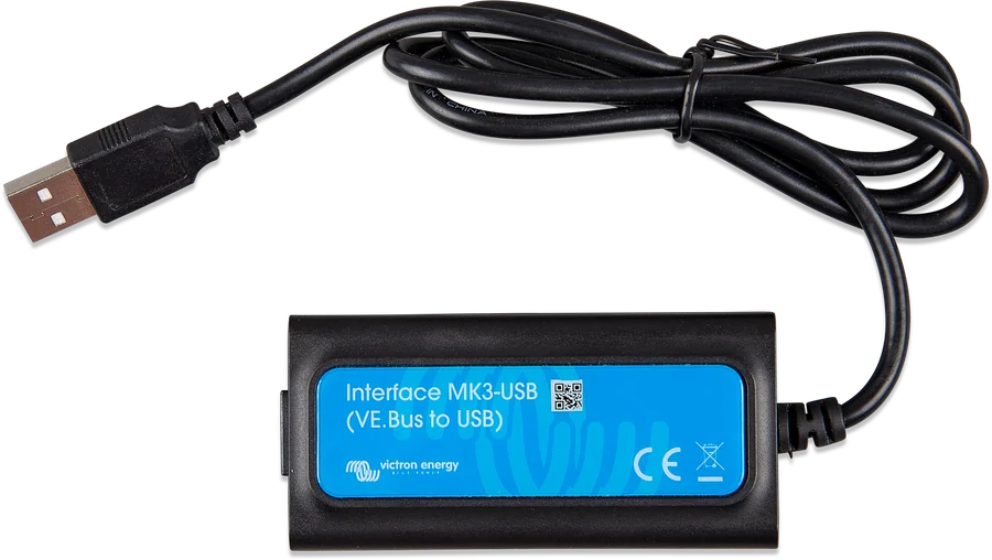
Inverter Control panel, GX device (for example Cerbo GX) for monitoring and VRM, VE.Bus–NMEA 2000 interface, and via MK3-USB — a computer with VictronConnect or VEConfigure.
Programmable relay
Alarm as standard (also for pre-alarms). You can set it, for example, to start a generator. Rating: AC 230 V / 4 A, DC 4 A up to 35 V and 1 A up to 60 V.
AES mode
Automatic Economy Switch reduces no-load and light-load consumption by about 20%, slightly “narrowing” the sine wave. In 3,000/5,000 VA units it is enabled with ds5; in Compact — only from a computer. It works in single operation.
Search mode
Reduces no-load consumption by about 70%: the inverter switches off and checks every 2 seconds whether a load has appeared. By default it switches off below 40 W and stays on from 100 W. In Compact it is enabled with ds6; in 3,000/5,000 VA units — from a computer.
Protections a–g
Short circuit and output overload, battery voltage too high and too low, temperature too high, 230 V fed to the output and excessive ripple on the DC input.
−40 to +65 °C
Fan cooling, humidity up to 95% non-condensing. Continuous power decreases with temperature — for example, 3,000 VA: 2,400 W at 25 °C, 1,700 W at 65 °C.
Output regulation
Voltage 210–245 V and frequency 50 or 60 Hz — 230 V / 50 Hz as standard. The most important settings are changed with DIP switches, all settings — from a computer.
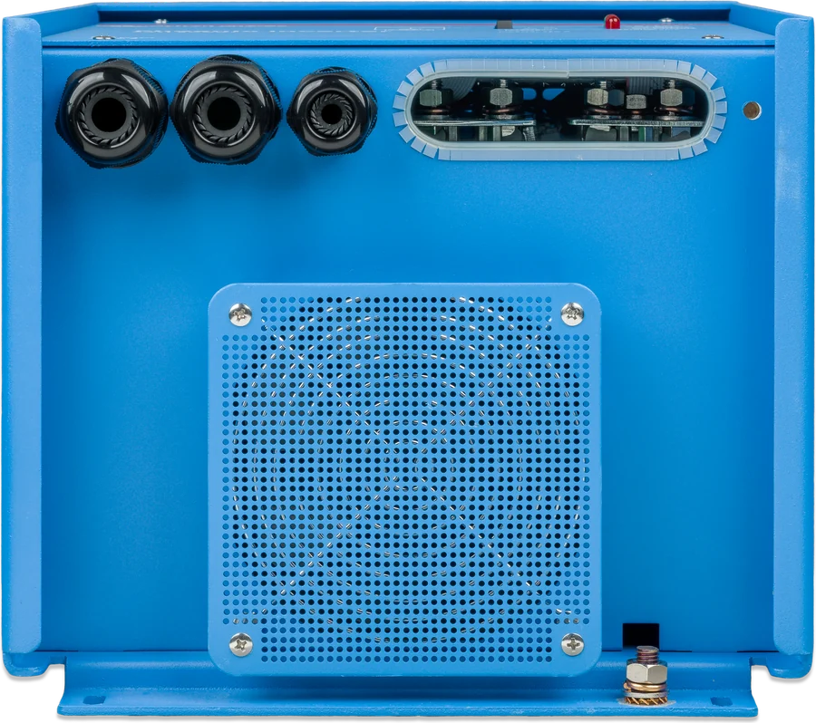
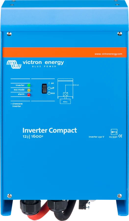
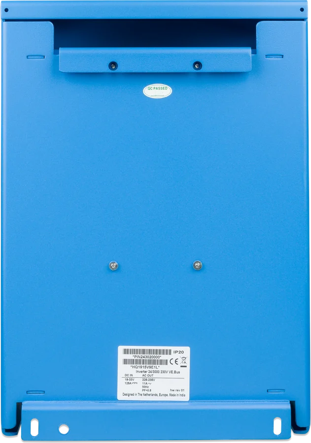
Eleven 230 V models
The letter C denotes the Compact series. In the model designation, the first number is the battery voltage, the second — the power in VA. The power in VA is given for a non-linear load with a crest factor of 3:1.
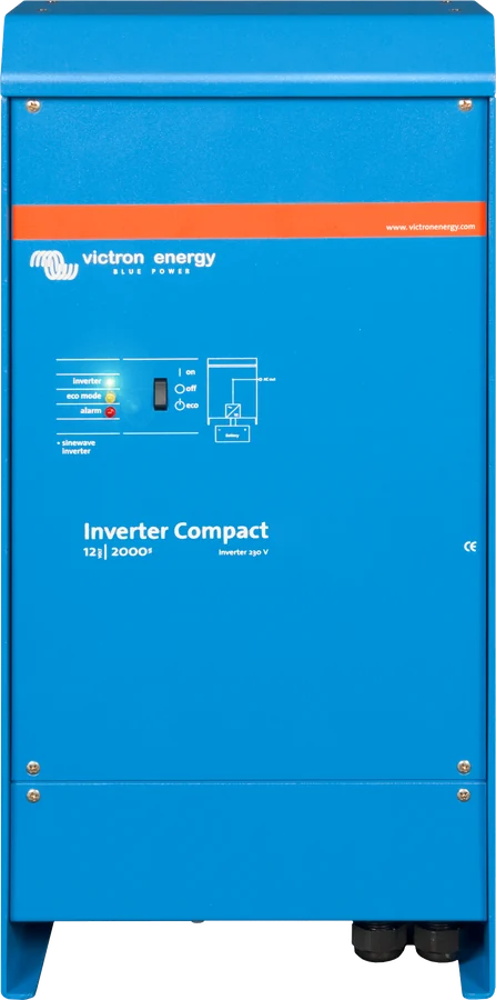
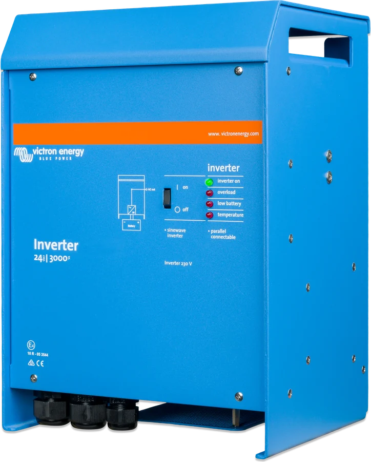
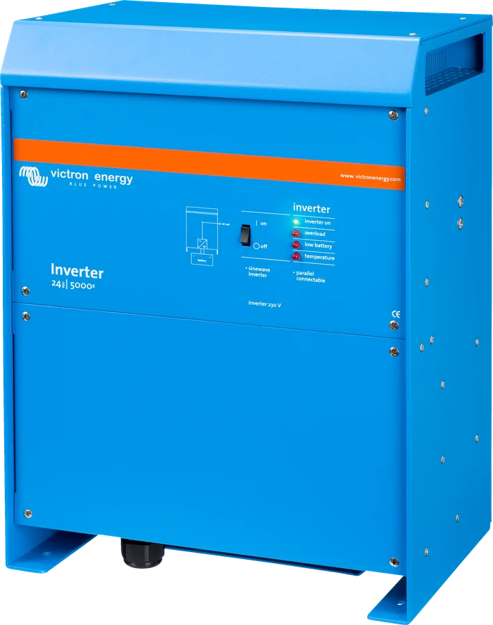
| Model | Battery | Power at 25 °C | Power at 40 °C | Power at 65 °C | Peak | Efficiency | No-load consumption | Weight |
|---|---|---|---|---|---|---|---|---|
| C12/1200, C24/1200 | 12 / 24 V | 1200 VA · 1000 W | 900 W | 600 W | 2400 W | 92 / 94% | 8 / 10 W | 10 kg |
| C12/1600, C24/1600 | 12 / 24 V | 1600 VA · 1300 W | 1200 W | 800 W | 3000 W | 92 / 94% | 8 / 10 W | 10 kg |
| C12/2000, C24/2000 | 12 / 24 V | 2000 VA · 1600 W | 1450 W | 1000 W | 4000 W | 92 / 92% | 9 / 11 W | 12 kg |
| 12/3000, 24/3000, 48/3000 | 12 / 24 / 48 V | 3000 VA · 2400 W | 2200 W | 1700 W | 6000 W | 93 / 94 / 95% | 20 / 20 / 25 W | 18 kg |
| 24/5000, 48/5000 | 24 / 48 V | 5000 VA · 4000 W | 3700 W | 3000 W | 10 000 W | 94 / 95% | 30 / 35 W | 30 kg |
- Output
- 230 V ±2%, 50 Hz ±0.1% (60 Hz and 240 V possible)
- DC range
- 9.5–17 V · 19–33 V · 38–66 V
- AES consumption
- 5–30 W depending on model
- Search mode consumption
- 2–15 W depending on model
- Enclosure
- aluminium, blue RAL 5012, IP21
- AC output
- 1200/1600: G-ST18i plug · 2000: spring clamp · 3000/5000: screw terminals
The table values come from the datasheet. The manual for the 3,000 VA models gives 92% efficiency for 12/3000 (datasheet: 93%), and for 3,000 and 5,000 VA models AC terminals of 13 mm² (6 AWG). The Compact 2000 manual gives a peak power of 3,500 W (datasheet: 4,000 W) and an AC connection of 6 mm². The 120 V versions have a separate datasheet.
Where the Phoenix Inverter sits in a system
Battery through a DC fuse, 230 V loads on the output, panel and GX device via VE.Bus. Hover over a diagram element or touch it. Schematic diagram.
- Battery → DC fuse125–400 A depending on model (3,000/5,000 VA); the Compact manuals do not give values.
- Phoenix InverterPure 230 V sine wave, earthed enclosure.
- 230 V output2.5 or 4 mm² cable (3,000/5,000 VA), 1.5 or 2.5 mm² (Compact 1200/1600) and residual current device.
- RelayAlarm or generator start.
- VE.BusInverter Control panel, GX, parallel or three-phase operation.
Phoenix VE.Bus, Inverter Smart or MultiPlus?
Phoenix Inverter (VE.Bus)
When you need parallel or three-phase operation, GX integration via VE.Bus and high starting power — also 48 V with 3,000 and 5,000 VA.
1200–5000 VA · VE.BusPhoenix Inverter Smart
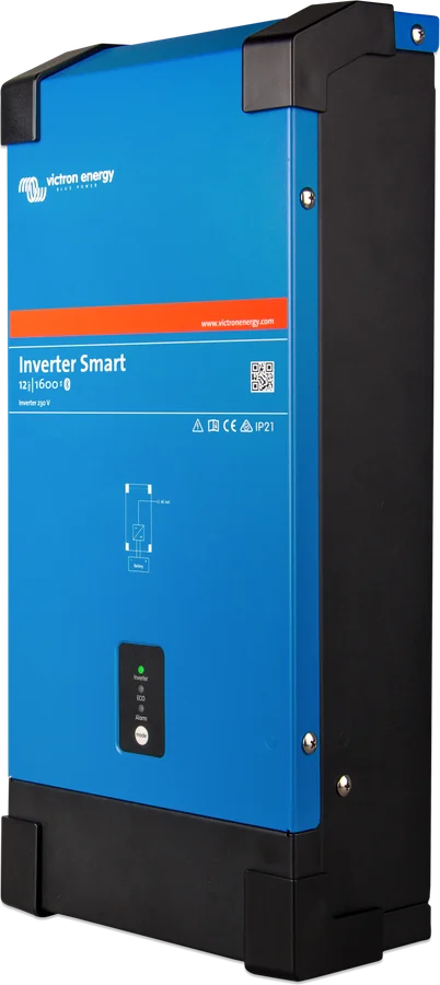
A newer series with Bluetooth and the VictronConnect app. Inverter Smart datasheet; lower powers: Phoenix VE.Direct 250–1600 VA.
Bluetooth · VE.DirectWhere and how to install
The battery is a permanent energy source — even a switched-off inverter may have dangerous voltage at the terminals. Before work, switch off AC and disconnect the battery. There are no user-serviceable parts inside; do not operate the unit without the covers fitted.
Connect the enclosure to earth, the vehicle chassis, or the grounding plate or boat hull. If you suspect an earth fault, the unit must be switched off and protected against being switched on again.
- A dry, ventilated place as close to the battery as possible, with at least 10 cm of free space around it. Never in a damp, dusty or gas- or dust-explosion-hazard area.
- Wall mounting — rear hook and two holes; vertical or horizontal, vertical cooling works better. The interior must remain accessible after installation.
- Heat-resistant surroundings: no chemicals, plastics, curtains or fabrics nearby. Never directly above batteries.
- For transport and storage, disconnect the battery cables; store between −20 and +60 °C, in a dry place.
- DC and AC cables with fuses and switches; replace protection devices only with the same type.
- On Compact units, reverse battery connection damages the unit (it may blow the internal fuse).
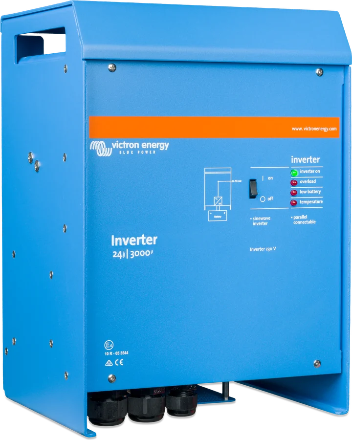
Up to six identical inverters of the same power; DC cables of the same length and cross-section, at least 10 cm clearance below, above and beside each unit. UTP cables directly from unit to unit (and to the panel), with no splitters. In the system, only one panel or one remote switch. Three-phase system — star (Y) only.
What to connect the inverter with
| Model | DC fuse | 0–5 m | 5–10 m | Battery capacity |
|---|---|---|---|---|
| 12/3000 | 400 A | 90 mm² | 120 mm² | 400–1200 Ah |
| 24/3000 | 300 A | 50 mm² | 90 mm² | 200–700 Ah |
| 48/3000 | 125 A | 35 mm² | 70 mm² | 100–400 Ah |
| 24/5000 | 400 A | 2 × 50 mm² | 2 × 90 mm² | 400–1400 Ah |
| 48/5000 | 200 A | 1 × 70 mm² | 2 × 70 mm² | 200–800 Ah |
The 3,000/5,000 VA manual: cross-section per pole, “2×” means two positive and two negative cables; battery cables must not be run in a closed conduit. Maximum torque on the battery terminals is 11 Nm, using a torque wrench with an insulated socket. AC cable: flexible three-core 2.5 or 4 mm².
| Compact | Cables included (1.5 m) | Recommended cross-section | Battery capacity |
|---|---|---|---|
| C24/1200 | 16 mm² | 1.5–5 m: 25 mm² · 5–10 m: 50 mm² | 40–400 Ah |
| C24/1600 | 25 mm² | 1.5–5 m: 35 mm² · 5–10 m: 70 mm² | 100–400 Ah |
| C12/1200 | 25 mm² | 1.5–5 m: 50 mm² · 5–10 m: 100 mm² | 150–700 Ah |
| C12/1600 | 35 mm² | 1.5–5 m: 70 mm² · 5–10 m: 140 mm² | 200–700 Ah |
| C24/2000 | — | up to 6 m: 50 mm² | 200–500 Ah |
| C12/2000 | — | up to 6 m: 70 mm² | 350–1000 Ah |
Compact series manuals do not specify the DC fuse value — select it according to the rules for choosing DC cable cross-sections and fuses. AC cable in the Compact 1200/1600: flexible three-core 1.5 or 2.5 mm².
DIP switches and computer
3000 and 5000 VA models
By default, the inverter is set for single operation: 230 V, 50 Hz, AES off, relay — alarm. The most important settings are changed with DIP switches, all settings — from a computer (VEConfigure3 via the MK3-USB interface). Parallel and three-phase operation is configured with software: up to three inverters — VE.Bus Quick Configure, from four onwards — VE.Bus System Configurator.
- ds5 — AES: off = disabled, on = enabled (single operation only).
- ds4 — voltage: off = 240 V, on = 230 V.
- ds3 — frequency: off = 60 Hz, on = 50 Hz.
- Save: with the inverter switched on (preferably with no load), hold the “Up” button for 2 s — the “overload” and “low battery” LEDs will flash. ds8, ds7, ds6, ds2 and ds1 remain in the off position.
Firmware. This manual applies to version xxxx400 or later. Older units can be updated if the 7-digit number starts with 26 or 27; if it starts with 19 or 20 — it cannot. In xxxx1xx firmware, ds1 and ds2 are used to set single, parallel or three-phase operation. For parallel operation, the easiest option is to set all inverters identically.
Compact 1200, 1600 and 2000 VA series
| Switch | Function |
|---|---|
| ds1, ds2 | control method: ds1 off / ds2 on — switch on the enclosure (factory default; also with GX or VE.Bus Smart dongle without a panel); ds1 on / ds2 off — Multi Control panel or VE.Bus BMS; ds1 off / ds2 off — remote 3-position switch |
| ds5 | frequency: off — 50 Hz, on — 60 Hz |
| ds6 | Search mode: off — disabled (factory default), on — enabled |
| ds8 | save: switch from off to on and back to off — the three LEDs flash four times |
On the Compact, output voltage and AES are set from a computer or a VE.Net panel. The factory settings were written by software, so in a new unit all switches except ds2 are in the off position and do not reflect the settings.
What the LEDs mean
3000 and 5000 VA models have four LEDs: “inverter on”, “overload”, “low battery” and “temperature”. Below are the situations from the fault table in their manual. Error codes for parallel and three-phase systems: VE.Bus errors; the Victron Toolkit app also shows the current codes by flashing.
Will not start after switching on
Battery voltage too high or too low, or no voltage at the DC terminals. Check the battery voltage and connections.
“low battery” flashes or stays on
Flashing: low battery voltage. On: the inverter has shut down due to low voltage. Charge the battery and check the connections.
“overload” flashes or stays on
Flashing: the load exceeds the rated power. On: the inverter has shut down due to overload or short circuit. Reduce the load.
“temperature” flashes or stays on
Ambient temperature too high or load too large. Move the inverter to a cooler, well-ventilated place or reduce the load.
“overload” and “low battery” flash alternately
Low battery and too much load. Charge the battery, reduce the load, use a larger battery or shorter, thicker cables.
“overload” and “low battery” together
Flashing — ripple at the DC terminals above 1.5 V rms (3000/5000 VA); on — the inverter has shut down for this reason. Check the cables and battery capacity, then switch the inverter off and on.
“inverter on” flashes in a VE.Bus system
Together with a flashing “overload” LED, this is an OK code — the unit is healthy and waiting for the others. A flashing “inverter on” LED on its own with the system switched off is a VE.Bus error, for example a damaged UTP cable. Switch off all devices, check the wiring and switch on again. You can read the details with VE.Bus System Configurator or Quick Configure.
“overload” and “low battery” flash after saving
This is how the inverter confirms that the DIP switch settings have been saved (the “Up” button for 2 s) — it is not a fault.
One alarm LED is on, the other is flashing
The LED that is on indicates the alarm that caused the inverter to shut down; the flashing LED indicates the alarm that would have caused it to shut down next.
Compact series — three LEDs: “inverter”, “eco mode” and “alarm”
“inverter” is on
The inverter is on and supplying the loads from the battery.
“eco mode” is on
The inverter is operating in energy-saving mode and supplying the loads.
The three LEDs flash four times
Confirmation that the settings were saved with the ds8 switch — this is not a fault.
“alarm” flashes
Early warning: low battery voltage, high temperature, overload or ripple at the DC input above 1.25 V rms. Charge the battery, cool the inverter or reduce the load, and check the cables.
“alarm” is on
The inverter has shut down after an early warning — check which cause occurred.
Will not start after switching on
Battery voltage too high or too low — or the processor has frozen: switch the enclosure switch off, wait 4 seconds and switch it back on.
Frequently asked questions about Phoenix Inverter
Will Phoenix Inverter switch loads to mains?
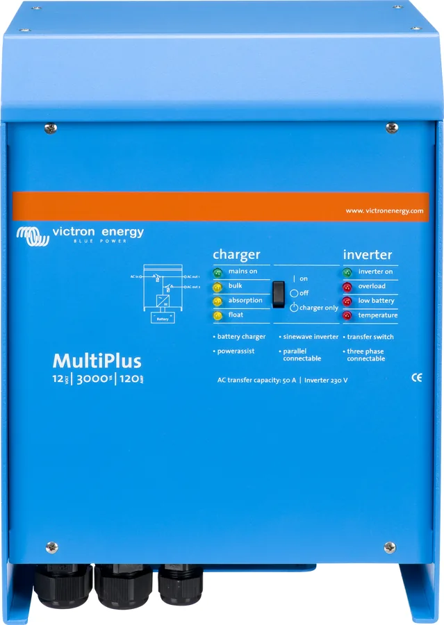
No — it has no transfer switch or charger. If you need an automatic transfer switch, the manufacturer recommends MultiPlus or Quattro: they switch in less than 20 ms, and their charger can be disabled.
How many inverters can I connect in parallel?
Up to six identical units of the same power rating. The datasheet gives an example: six 24/5000 units make 24 kW / 30 kVA. The inverters can also be connected in a three-phase system — star only — and the Compact series also in split-phase. All units should have identical settings.
Which fuse and cable for 24/3000?
300 A fuse, 50 mm² cable per pole for lengths up to 5 m and 90 mm² for 5–10 m. Recommended battery: 200–700 Ah.
What is different about the Compact series?
These are 1200, 1600 and 2000 VA models for 12 and 24 V in a smaller enclosure. The 1200 and 1600 VA models come with 1.5 m battery cables and a G-ST18i plug on the output, the 2000 VA model has M8 screws and a spring terminal. They also have VE.Bus, parallel operation and three-phase operation.
How can I reduce no-load current consumption?
AES mode reduces it by about 20%, and Search mode by about 70%: the inverter switches off with no load and checks every 2 seconds whether something has switched on. In the 3000/5000 VA models, AES is enabled with switch ds5 and Search with the computer; in the Compact, it is the other way round: Search is switch ds6, AES is the computer. Both work only in single operation.
Can I change the voltage to 240 V or 60 Hz?
Yes. In the 3000/5000 VA models, switch ds4 selects 230 or 240 V, and ds3 — 50 or 60 Hz. In the Compact, switch ds5 changes only the frequency, and the voltage is changed from the computer. From the computer, voltage is set in the range 210–245 V.
How do I connect the inverter to Cerbo GX?
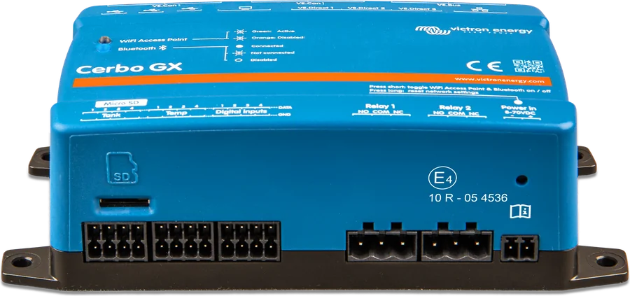
Use an RJ45 UTP cable to the VE.Bus socket. GX provides monitoring and the VRM portal. To change settings from a computer, you need the MK3-USB interface.
Do I need an RCD for Phoenix Inverter?
The output neutral conductor is connected to the enclosure specifically so that the residual current device (RCCB) fitted on the inverter output will operate. The enclosure must be earthed or connected to the vehicle chassis or hull.
Devices it works with most often
Manufacturer documentation
- Inverters 1200 VA – 5000 VA — datasheetvictronenergy.com · PDF · EN
- Manual Inverter 3k–5k 230 V (firmware xxxx4xx)victronenergy.com · PDF · EN
- Manual Inverter Compact 1200 and 1600 VAvictronenergy.com · PDF · EN
- Manual Inverter Compact 2000 VAvictronenergy.com · PDF · EN
- Inverter — product pagevictronenergy.com · EN
Content checked against Victron Energy documentation (datasheets and manuals) — as of 22 September 2026. Report a content error · Revision log