
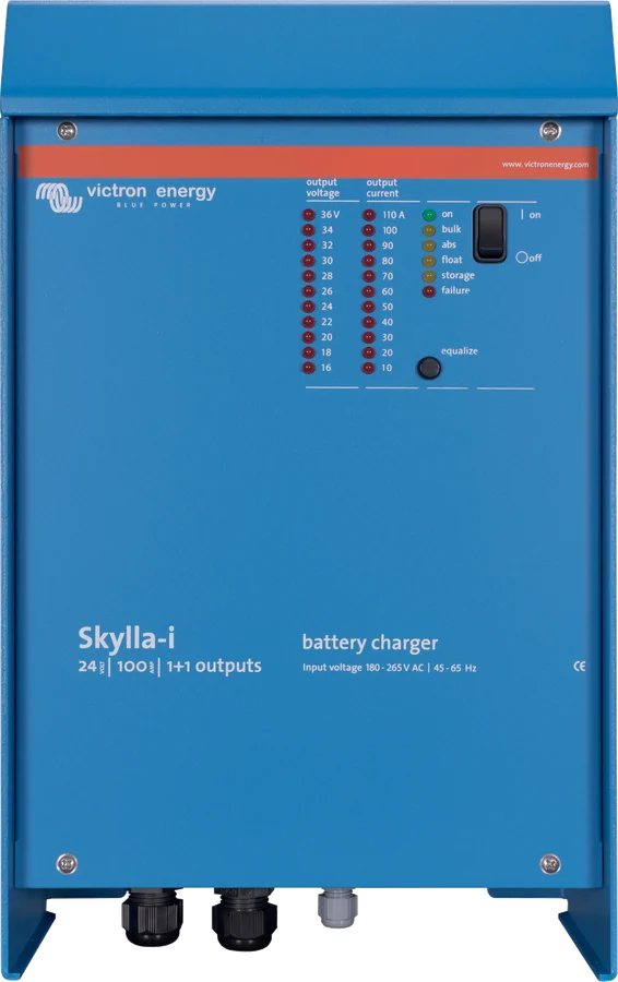
Skylla-i 24/100 (1+1) — front with status LEDs, two outputs
Skylla-i, Skylla-TG and Skylla-IP65
Victron’s large mains chargers: up to 100 A at 24 V and 50 A at 48 V, in wall-mount enclosures with forced cooling. The three series differ in algorithm, communications and enclosure. What they have in common is operation with lead-acid batteries of various types (Skylla-i and IP65 also with LiFePO4), a temperature sensor, battery terminal voltage measurement and the option to operate as a power supply.
- 12 V · 24 V · 48 V
- 25–100 A
- 90–265 V AC or DC
- IP21 · IP65
- VE.Can (i, IP65)
One charger for a large battery bank and a power supply in one
Skylla is a range of powerful, stationary chargers for permanent installation: on yachts and ships, in vehicles and trailers, in industry and wherever a 24 V or 48 V battery bank has several hundred amp-hours. According to the Skylla-TG manual, the charger may be connected to the battery permanently, including over winter.
Thanks to its stable output voltage, Skylla also works as a power supply when there is no battery or large buffer capacitors in the installation. Skylla-i and single-phase Skylla-TG accept DC supply as well as AC mains (lower limit 90–180 V DC, depending on model).
- direct voltage measurement at the battery terminals (voltage sense) compensates for cable drop,
- battery temperature sensor supplied — charge voltage decreases as the battery warms up,
- versions with a 3–4 A auxiliary output for a starter battery or with three full-current outputs.
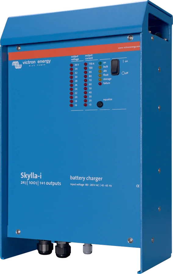

How Skylla-i, Skylla-TG and Skylla-IP65 differ
| Skylla-i | Skylla-TG | Skylla-IP65 | |
|---|---|---|---|
| Battery | 24 V | 24 i 48 V | 12 i 24 V |
| Current | 80 or 100 A | 25–100 A | 70 A (12 V), 35 A (24 V) |
| Supply voltage | 185–265 V AC, 180–350 V DC | 230 V, 3 × 400 V; 90–265 V AC versions | 90–265 V AC |
| Algorithm | 7-stage, adaptive, storage | IUoUo, three stages | 7-stage, adaptive, storage |
| Battery selection | rotary switch, DIP switches, potentiometers | factory set; DIP switches and potentiometers inside | menu on the LCD display |
| Lithium (LiFePO4) | position 7, BMS control | not in the manual | algorithm 7, BMS control |
| Communication | VE.Can (isolated) | no VE.Can; analogue panels (GMDSS: VE.Net panel) | VE.Can (non-isolated) |
| Parallel operation | yes, via VE.Can | not in the manual | up to 10 units via VE.Can |
| Enclosure | aluminium, IP21 | aluminium, IP21 | steel, IP65 |
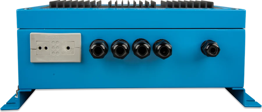
What Skylla chargers can do
Absorption depending on discharge depth
Skylla-i and IP65: after a shallow discharge, absorption is short; after a deep discharge, it is longer. In Skylla-i, absorption and float last 20 × bulk time (absorption at least 30 min, float 4–8 h).
BatterySafe
Skylla-i and IP65: when a high absorption voltage is set, above gassing voltage (14.4 / 28.8 V) the voltage rises by no more than 7 / 14 mV per minute — the battery does not gas vigorously.
Storage mode
Skylla-i and IP65: after the float stage, voltage drops to 2.2 V per cell (13.2 / 26.4 V), and once a week it returns to absorption for one hour — less gassing and corrosion, without electrolyte stratification.
Temperature compensation
Sensor supplied. In Skylla-i: −32 mV/°C for a 24 V battery; the sensor is mandatory when the battery is below 15 °C or above 30 °C, or when current exceeds 15 A per 100 Ah.
Voltage sense
Two 0.75 mm² wires from the battery terminals. Skylla-TG compensates for up to 2 V drop — above that it reports an error and you need thicker cables.
Parallel operation
Skylla-i and IP65 synchronise via an RJ45 cable through VE.Can (IP65 up to 10 units). Connect the sensors to one charger; the rest receive the data from the bus.
Shore current limit
The Skylla-i Control panel (or a GX device) limits the current drawn from the marina hook-up or a small generator — for the whole group of chargers at once. Skylla-TG has a Skylla Control analogue panel.
Power supply mode
Constant voltage without a battery: Skylla-i default 24 V (adjustable 11.5–33.5 V), IP65 12 V or 24 V; in Skylla-TG every charger can be used as a power supply thanks to the stabilised output.
Alarm relay
Potential-free NO/NC contacts. In Skylla-i, energised (COM–NO) when charging is running without an error and voltage is within 23.7–33.6 V; in IP65, nine modes to choose from.
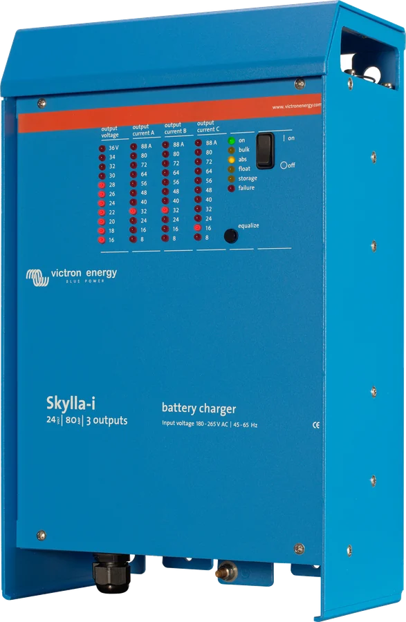
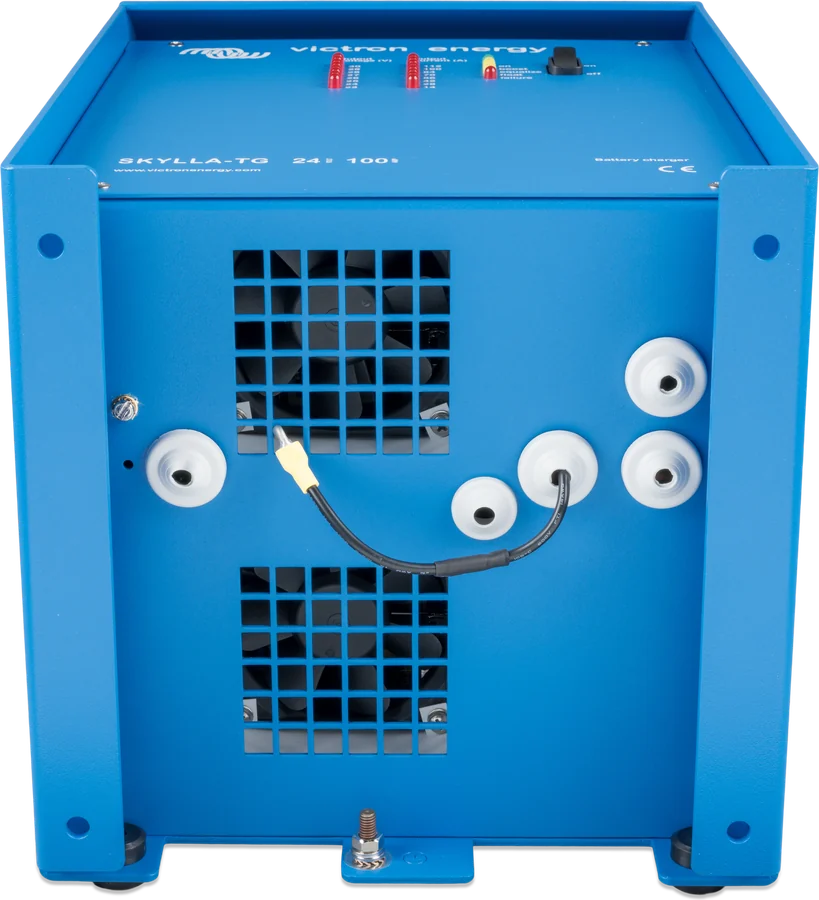
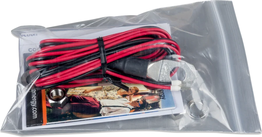
All Skylla models
The designation is the battery voltage and charging current: 24/100 = 24 V battery, 100 A. “(1+1)” — main output and auxiliary output for the starter battery; “(3)” — three isolated outputs that together deliver the rated current. Full current up to 40 °C ambient.
Skylla-i — 24 V, 230 V
| Skylla-i | 24/80 (1+1) | 24/80 (3) | 24/100 (1+1) | 24/100 (3) |
|---|---|---|---|---|
| Charge current | 80 A | 3 × 80 A (80 A total) | 100 A | 3 × 100 A (100 A total) |
| Starter output | 4 A | — | 4 A | — |
| Recommended battery | 400–800 Ah | 400–800 Ah | 500–1000 Ah | 500–1000 Ah |
| AC current at 180 V | 16 A | 16 A | 20 A | 20 A |
185–265 V AC or 180–350 V DC supply, power factor 0.98. 7-stage adaptive algorithm: absorption 28.8 V, float 27.6 V, storage 26.4 V (adjustable output 20–36 V). Aluminium IP21 enclosure, 405 × 250 × 150 mm, 7 kg, M8 screws, 10 mm² AC terminal. Operating temperature −20…+60 °C; above 40 °C current falls to 80% at 50 °C and 60% at 60 °C.
Skylla-TG — 24 and 48 V, including three-phase
| Skylla-TG | AC supply | DC input | Current | Starter | Battery | Weight |
|---|---|---|---|---|---|---|
| 24/30 | 120/230 V (95–264 V) | 120–400 V | 30 A | 4 A | 150–500 Ah¹ | 5.5 kg |
| 24/50 | 230 V (185–264 V) | 180–400 V | 50 A | 4 A | 150–500 Ah¹ | 5.5 kg |
| 24/50 3-phase | 3 × 400 V (320–450 V) | — | 50 A | 4 A | 250–500 Ah | 13 kg |
| 24/80 | 230 V (185–264 V) | 180–400 V | 80 A | 4 A | 400–800 Ah | 10 kg |
| 24/100 | 230 V (185–264 V) | 180–400 V | 100 A | 4 A | 500–1000 Ah | 10 kg |
| 24/100 3-phase | 3 × 400 V (320–450 V) | — | 100 A | 4 A | 500–1000 Ah | 23 kg |
| 48/25 | 230 V (185–264 V) | 180–400 V | 25 A | — | 125–250 Ah | 5.5 kg |
| 48/50 | 230 V (185–264 V) | 180–400 V | 50 A | — | 250–500 Ah | 10 kg |
¹ The datasheet gives one common range for 24/30 and 24/50; the version with universal input is specified as 150–300 Ah for 24/30. The manuals give lower ranges, for example 24/30 and 48/25 — 100–200 Ah, 24/80 — 300–600 Ah, 48/50 — 200–400 Ah. IUoUo characteristic (three stages): 28.5 / 26.5 V for 24 V and 57 / 53 V for 48 V. Three-phase models do not accept DC supply. Aluminium IP21 enclosure, M8 bolts, 2.5 mm² AC terminal according to the datasheet (manuals: terminal strip up to 4 mm², 24/100 3-phase up to 10 mm²). Operating temperature −40…+50 °C according to the datasheet; TG manuals state 0…+40 °C and power derating above 40 °C. Alarm relay: potential-free contacts 60 V / 1 A (NO and NC). Dimensions: 24/30, 24/50 and 48/25 — 365 × 250 × 147 mm; 24/50 3-phase, 24/80, 24/100 and 48/50 — 365 × 250 × 257 mm; 24/100 3-phase — 515 × 260 × 265 mm.
Skylla-TG with universal input and GL approval
| Universal input and GL | 24/30 | 24/50 | 24/100-G |
|---|---|---|---|
| Supply voltage | 90–265 V AC, 90–400 V DC | 90–265 V AC, 90–400 V DC | 90–265 V AC, 90–400 V DC |
| Current / starter | 30 A / 4 A | 50 A / 4 A | 100 A / 4 A |
| Recommended battery | 150–300 Ah | 250–500 Ah | 500–1000 Ah |
| Dimensions / weight | 365 × 250 × 147 mm, 5.5 kg | 365 × 250 × 147 mm, 5.5 kg | 365 × 250 × 257 mm, 10 kg |
They operate without adjustment from 90 to 265 V AC (50 or 60 Hz). Germanischer Lloyd approval category C, EMC 1 — meets emission limits for equipment mounted on a ship’s bridge (IEC 60945); the approval covers 185–265 V AC supply. Beside them are GMDSS versions 24/30 and 24/50 for supplying a marine distress and safety communications system — with a built-in battery controller and a separate VE.Net GMDSS panel, which shows battery runtime after a power failure. In the 24/30 GMDSS at 110 V AC, current drops to 22 A.
Skylla-IP65 — 12 and 24 V, sealed
| Skylla-IP65 | 12/70 (1+1) | 12/70 (3) | 24/35 (1+1) | 24/35 (3) |
|---|---|---|---|---|
| Charge current | 70 A | 3 × 70 A (70 A total) | 35 A | 3 × 35 A (35 A total) |
| Starter output | 3 A | — | 3 A | — |
| Absorption / float / storage | 14.4 / 13.8 / 13.2 V | 14.4 / 13.8 / 13.2 V | 28.8 / 27.6 / 26.4 V | 28.8 / 27.6 / 26.4 V |
| Recommended battery | 350–700 Ah | 350–700 Ah | 150–350 Ah | 150–350 Ah |
90–265 V AC supply (datasheet: up to 12 A at 100 V AC; according to the manual the factory limit is 10.5 A and never more than 1,050 W), 7-stage algorithm. Steel IP65 enclosure with internal air circulation, 401 × 265 × 151 mm, 6 kg, M6 bolts, 6 mm² AC terminal. VE.Can port without galvanic isolation. Operating temperature −20…+60 °C; above 40 °C current drops to 60% at 50 °C and 40% at 60 °C.
Where the Skylla sits in the installation
Mains or shore power at the input, house battery and starter battery at the outputs, sense wires to the battery and an optional BMS. Hover over a diagram element or touch it. Schematic illustration.
- Mains → SkyllaPE, N, L; Skylla-i: battery type before applying AC, IP65: in the menu before connecting the battery.
- Skylla → house batteryCables according to the cross-section table, maximum 6 m.
- Voltage sense and sensorSense 0.75 mm² from the battery terminals; sensor on the battery (Skylla-i: on the negative).
- Starter battery(1+1) versions and Skylla-TG 24 V: 3–4 A output.
- BMS (lit)Remote on/off input (Skylla-i, IP65).
- Panel or GXVE.Can with terminators (Skylla-i, IP65).
Skylla or another Victron charger?
Skylla-i
24 V, 80 or 100 A, adaptive algorithm with storage mode, VE.Can for parallel operation and the Skylla-i Control panel. For large banks on yachts and in vehicles.
24 V · 80/100 A · VE.CanSkylla-TG
24 and 48 V, 25–100 A, also with three-phase supply, universal input, GL approval and a GMDSS version. Simple three-stage algorithm, without VE.Can (GMDSS — with a digital VE.Net panel).
24/48 V · 25–100 A · 3 × 400 VSkylla-IP65
12 V 70 A or 24 V 35 A in an IP65 enclosure with LCD display and VE.Can. For places exposed to moisture, dust and salty air.
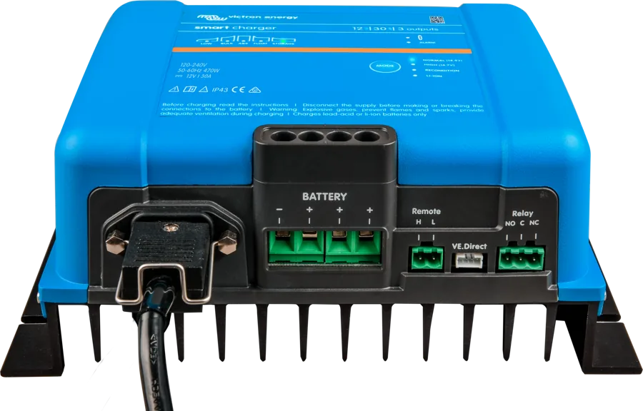
12/24 V · 35/70 A · IP65For smaller systems, chargers with Bluetooth are enough: Smart IP43 (up to 50 A, also 48 V), Blue Smart IP22 (up to 30 A) and Blue Smart IP65. If you also need a 230 V inverter, the charger is built into MultiPlus-II or Quattro.
Installation rules and cable cross-sections
None of the series is protected against reversing battery + and −; damage caused by this is not covered by the warranty. Skylla-TG 24/80, 24/100 and 48/50 have a polarity check tool: the green LED lights up when connected correctly. Universal-input versions too. In the standard 24/30, 24/50 (including 3-phase) and 48/25, remove the output fuses first — the red LED indicates reverse polarity.
Before working on the charger, disconnect the AC supply. The manufacturer requires fuses and switches in the cables, but does not specify their ratings — the installer selects them according to the cable cross-section.
- Location: dry, ventilated, with no chemicals or fabrics nearby; wall-mounted (preferably vertical — better airflow) or on the floor. Battery cables shorter than 6 m. IP65 needs free airflow at the back of the enclosure.
- Sequence (Skylla-i): mains disconnected → cables to the charger → cables to the battery → battery type → AC supply (PE, N, L). In IP65, select the algorithm in the menu with the mains on, before connecting the battery. Disconnecting: first negative, then positive, then sensors.
- Earthing: the enclosure earthing point on a vessel to the hull or earthing plate, on land to mains PE, in a vehicle to the chassis. In Skylla-i and IP65 the battery terminals are isolated from the enclosure.
- Remote on/off in Skylla-i: without a switch the terminals must be bridged with a wire, otherwise the charger will not start. In IP65 the bridge is fitted from the factory.
- A diode splitter (Argo) and voltage sense at the same time give too high a voltage — in Skylla-TG, use the ‘split’ switch for the splitter (+0.6 V).

Minimum battery cable cross-section
| Model | up to 1.5 m | 1.5–6 m |
|---|---|---|
| Skylla-i 24/80 | 25 mm² | 35 mm² |
| Skylla-i 24/100 | 35 mm² | 50 mm² |
| Skylla-TG 24/30, 48/25 | 6 mm² | 10 mm² |
| Skylla-TG 24/50, 24/50 3-phase, 48/50 | 10 mm² | 16 mm² |
| Skylla-TG 24/80 | 16 mm² | 25 mm² |
| Skylla-TG 24/100, 24/100 3-phase | 35 mm² | 50 mm² |
| Skylla-IP65 12/70 | 10 mm² | 16 mm² |
| Skylla-IP65 24/35 | 6 mm² | 10 mm² |
In Skylla-i models (3), the stated cross-section applies to the cable to each battery. Skylla-TG 24/80, 24/100 and 48/50 — terminal tightening torque 12 Nm. The IP65 cable gland accepts a lug up to 16 mm² (M6 bolt). Mains connection: Skylla-i 10 mm², Skylla-TG 2.5 mm² according to the datasheet (manuals: terminal strip up to 4 mm²), IP65 6 mm².
How to set the battery type
Skylla-i — rotary switch, DIP switches and potentiometers on the board behind the front cover. Settings are selected before applying AC supply; in model (3) they apply to all three outputs. The “reset settings” button (5 s) restores factory settings.
Skylla-IP65 has the same algorithms in the display menu: with the mains on, before connecting the battery, hold SETUP for 3 s (the charger enters standby); position 04 is the algorithm. In IP65 24 V, absorption, float and storage are as in Skylla-i 24 V; equalisation differs.
- DIP in Skylla-i: DS-6 — shut-down after 10 h of bulk phase; DS-5 and DS-4 — absorption time 2, 4, 8 (factory) or 12 h; DS-3 — adaptive mode; DS-2 — start in storage when the battery is above 26 V; DS-1 — automatic equalisation.
- Lithium: position 7, absorption time 2 h (DS-5 and DS-4 off). No float, no equalisation and no temperature compensation.
- Skylla-TG is factory set to 28.5 / 26.5 V (24 V) and 57 / 53 V (48 V). Adjustment — DIP switches and potentiometers inside, for a qualified electrician only: equalisation time 0/4/8/12 h, traction mode (+2 V at 24 V), “split” for diode splitter, fixed boost.
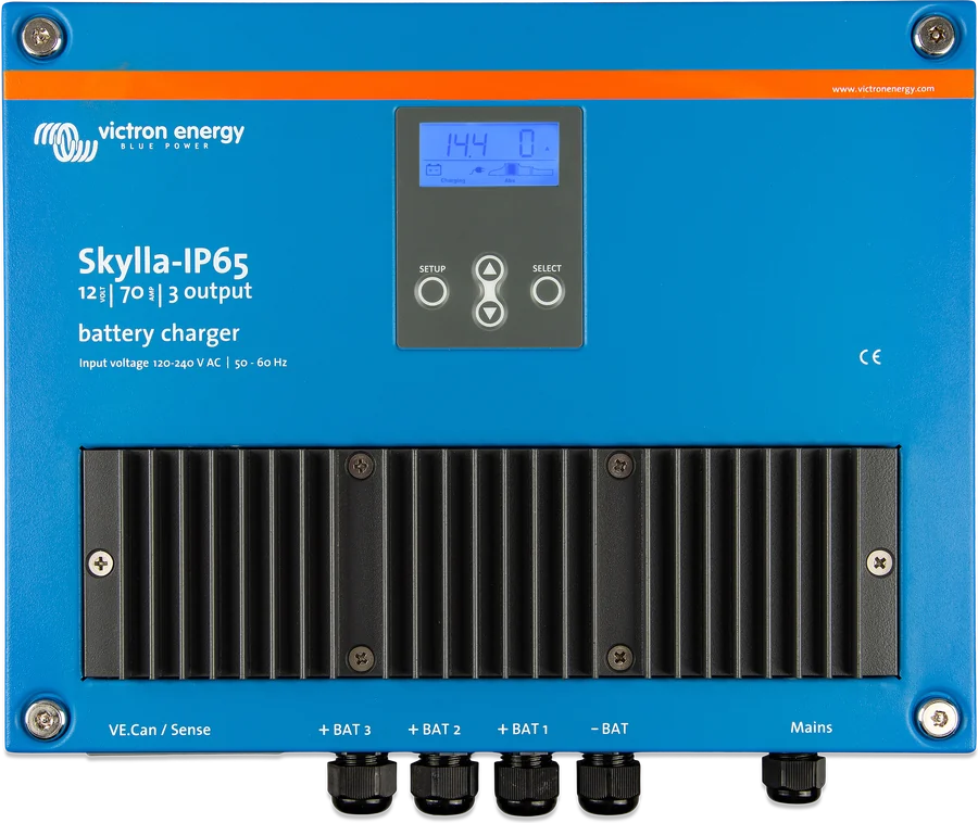
Switch positions (Skylla-i) and algorithms (IP65)
| Pos. | Battery type | Skylla-i 24 V: absorption / float / storage | IP65 12 V: absorption / float / storage |
|---|---|---|---|
| 1 | Victron long life gel (OPzV), Exide A600, MK gel | 28.2 / 27.6 / 26.4 V | 14.1 / 13.8 / 13.2 V |
| 2 | Default: Victron deep discharge gel and AGM, Exide A200, OPzS, Rolls flooded | 28.8 / 27.6 / 26.4 V | 14.4 / 13.8 / 13.2 V |
| 3 | Spiral AGM, Rolls AGM | 29.4 / 27.6 / 26.4 V | 14.7 / 13.8 / 13.2 V |
| 4–6 | PzS / OPzS tubular plate batteries in cyclic use (modes 1–3) | absorption 28.2 / 28.8 / 30.0 V | absorption 14.1 / 14.4 / 15.0 V |
| 7 | LiFePO4 | 28.4 V / — / 26.7 V | 14.2 V / — / 13.5 V |
| 8 | Custom settings | potentiometers: current, absorption, float | in the menu |
| 9 | Power supply mode | 24.0 V | 12.0 V |
The voltages are approximate — the manufacturer instructs you to check them with the battery manufacturer. Equalisation in Skylla-i: current 8% of bulk current (positions 1–3, maximum 1 h) or 25% (tubular plates, maximum 4 h); in IP65 — 6%. Do not enable equalisation if the battery manufacturer does not recommend it. In the IP65 manual, position 5 has the storage values for 12 and 24 V swapped.
What you need to watch
Limits gathered from the manuals and datasheets of the three series.
Skylla-TG without lithium mode and communication
The TG manuals do not describe LiFePO4 charging, parallel operation or VE.Can — only alarm contacts, remote on/off and analogue panels (the GMDSS version has a digital VE.Net panel).
DVCC does not control Skylla
The GX device does not limit Skylla-i chargers and does not include their current in the DVCC limit. The charger must be stopped by the BMS itself: by a wire to the remote on/off input or via VE.Can.
(1+1) and (3) separately
In a parallel Skylla-i group, you cannot mix models with two and three outputs (80 A and 100 A — you can). DIP and switch settings must be identical.
IP65 — 1,050 W from mains
The input power of one IP65 never exceeds 1,050 W; below 110 V the output current falls, and at 100 V to 50%.
Less current in the heat
Full current up to 40 °C. Skylla-i: 80% at 50 °C and 60% at 60 °C; IP65: 60% and 40%; Skylla-TG reduces current when it gets too hot.
VE.Can and 48 V devices
Skylla-i powers the 12 V bus and accepts a maximum of 30 V; in a system with 48 V devices you need an RJ45 cable without pins 2 and 6.
Most common faults
Typical situations from the manual. You can check the error code from the Skylla-i Control panel, IP65 display or GX device in the charger and MPPT error codes section — Skylla codes are listed there together with controller codes.
Charger does not start
Check the mains voltage (Skylla-i 180–265 V, TG 185–265 V (24/30 from 95 V), universal versions and IP65 from 90 V). In Skylla-i — whether the remote on/off terminals are shorted. Blown input fuses: send the unit for service.
Battery not fully charged
Wrong battery type in the settings, poor contact, cables too thin (use thicker ones or voltage sense), in TG too short an equalisation time or blown output fuses.
Battery overcharged
Wrong battery type, damaged cell, battery in a warm place without a temperature sensor; in TG — fixed boost enabled.
Error after 10 h of charging
Skylla-i and IP65: bulk phase lasted more than 10 h — damaged cell or charger too weak for the bank. In domestic solar installations the manufacturer recommends disabling this protection (DS-6). After 10 h Skylla-TG switches to float without an error.
Error LED lights or flashes (TG)
Steady on — shutdown due to overheating; flashing — current limited because of temperature. Two flashes and a one-second pause — blown output fuses. Steady on, while the “on” LED flashes — voltage drop in the cables above 2 V.
Sensor error disappeared after restart
Skylla-i: if the temperature sensor or voltage sense wire breaks, the error disappears after restart and the charger keeps charging without compensation. After the repair, check the sensor connection indication LEDs.
Error LED flashes in the group
One charger has disappeared from VE.Can — reconnect it or switch the remaining ones off and on. Check the terminators at both ends of the bus.
Charger is waiting for the BMS
After losing connection with the BMS, Skylla-i returns to standalone operation when you hold the reset button for 5 s; IP65 — after setting “BMS present” to N (menu 31).
IP65: plug icon flashes
Mains voltage is lower than normal — the charger is limiting output current.
Most common Skylla charger questions
Which Skylla should you choose for a yacht with a 24 V bank?
Skylla-i, if you want storage mode, parallel operation, a panel with shore current limit and BMS control; Skylla-TG, if a simple three-stage algorithm is enough or you need 3 × 400 V supply, wide input range or GL approval. In a damp location — IP65 (24/35). Comparison: three series.
Will Skylla charge a LiFePO4 battery?
Skylla-i and IP65 — yes: position or algorithm 7 (28.4 V absorption at 24 V), and the BMS switches the charger off via the remote on/off input or controls it via VE.Can. The Skylla-TG manuals do not provide for a lithium mode.
What current does it draw from a shore power socket?
Skylla-i at 180 V AC up to 16 A (80 A) or 20 A (100 A). IP65 factory set to a maximum of 10.5 A and no more than 1,050 W. You can set less with a Skylla-i Control panel or from GX — the limit applies to the whole charger group.
Can you connect several Skyllas in parallel?
Skylla-i and IP65 — yes, with RJ45 cables via VE.Can, with terminators at both ends; up to 10 IP65 units. Settings must be identical, and Skylla-i (1+1) and (3) models must not be mixed. The Skylla-TG manuals do not describe parallel operation.
Can Skylla run from DC power?
Skylla-i and single-phase Skylla-TG — yes (three-phase no; the IP65 datasheet does not provide for DC supply): Skylla-i 180–350 V DC, Skylla-TG 180–400 V DC (24/30: 120–400 V, universal versions 90–400 V).
What is the “starter battery” output?
In (1+1) versions, a second output for the starter battery: 4 A (IP65 — 3 A according to the datasheet), at a slightly lower voltage. The starter battery can draw current from the main battery, but not the other way round.
Will Skylla-i be visible in the GX device?
Skylla-i and IP65 connect to GX via VE.Can. However, the GX manual notes that DVCC does not control Skylla-i chargers and does not account for their current — with a lithium battery, the charger must be stopped by the BMS itself, by a wire to the remote input or via VE.Can.
What is the difference between Skylla GMDSS?
It is a Skylla-TG 24/30 or 24/50 with a built-in battery controller for powering the GMDSS system on ships. The battery and the GMDSS system are connected directly to the charger, and the separately ordered VE.Net GMDSS panel shows data, alarms and battery runtime.

Manufacturer documentation
- Skylla-i 24 V — datasheetvictronenergy.com · PDF · EN
- Skylla-i — manualvictronenergy.com · PDF · EN and others
- Skylla-i Control — panel manualvictronenergy.com · PDF · EN and others
- Skylla-TG 24/48 V — datasheetvictronenergy.com · PDF · EN
- Skylla-TG 24 V with universal input and GL approval — datasheetvictronenergy.com · PDF · EN
- Skylla-TG 24/80, 24/100, 48/50 — manualvictronenergy.com · PDF · EN
- Skylla-TG 24/30, 24/50, 24/50 3-phase, 48/25 — manualvictronenergy.com · PDF · EN
- Skylla-TG with universal input — manualvictronenergy.com · PDF · EN
- Skylla-TG GMDSS — datasheetvictronenergy.com · PDF · EN
- Skylla-IP65 — datasheetvictronenergy.com · PDF · EN
- Skylla-IP65 — manual (online version)victronenergy.com · EN
- Cerbo GX manual — DVCC (Skylla-i chargers outside control)victronenergy.com · EN
Content checked against Victron Energy documentation (datasheets and manuals) — as of 22 September 2026. Report a content error · Revision log