
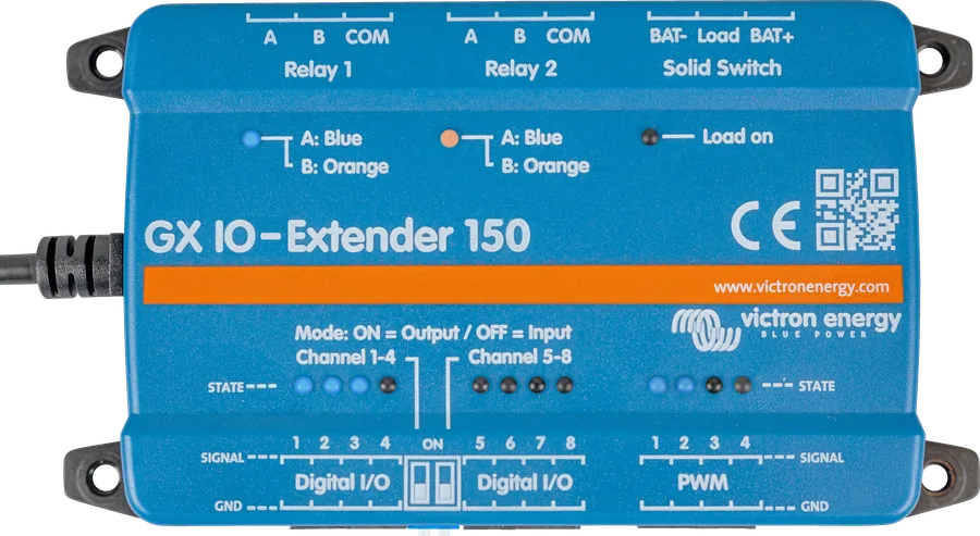
Top view of GX IO-Extender 150 — Relay 1, Relay 2, Solid Switch, Digital I/O and PWM labels on the housing
GX IO-Extender 150
A module connected to the USB port of a GX device (Cerbo GX, Ekrano GX) that adds eight digital inputs or outputs, four PWM outputs, two latching relays and an electronic DC switch. It is powered from USB. You control it from the switch panel in GX or from Node-RED. It is for signalling and control, not for switching large loads.
- 8 × digital I/O
- 4 × PWM 5 V
- 2 × latching relay
- 4 A / 70 V DC switch
- USB-powered
More inputs and outputs for your GX device
Cerbo GX has a few digital inputs and two relays. If that is not enough — because you want to read a door sensor, bilge alarm and pulse counter, switch on a warning lamp, dim LED lighting or energise a contactor coil — the GX IO-Extender 150 adds more ports. Once connected to USB, they appear immediately in the system.
It is most useful together with Node-RED on a GX device running Venus OS Large: the ports are available as Switch and Switch control nodes, so you can build your own logic, for example switch an output on when the battery state of charge drops below a threshold.
- works with all GX devices, but Node-RED is not available on every one of them,
- all ports have status LEDs (blue or orange),
- digital inputs and outputs, PWM and the DC switch are isolated from USB; the relays have volt-free contacts.
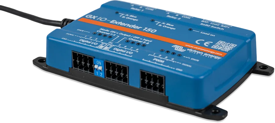
The relays and DC switch have a low current rating, depending on voltage. For switching loads in a Victron installation, Victron recommends dedicated switching systems (e.g. Energy Solutions, Garmin, Safiery) — the module itself can at most drive, for example, a contactor coil.
What the GX IO-Extender 150 has
8 digital inputs or outputs
Two groups of four ports. The DIP switch next to each group sets it as inputs (OFF) or outputs (ON) — 8 inputs, 8 outputs or 4 + 4 in total.
4 PWM outputs
5 V signal for dimming LEDs, speed control of motors and similar applications. The LED brightness at the port corresponds to the set value.
2 latching relays
A, B and COM contacts. A short pulse changes the position, and the relay holds it without power — even after the GX is switched off.
DC switch (Solid Switch)
Electronic, contactless, switches the positive side of a DC circuit up to 70 V and 4 A. Handles capacitive and inductive loads, e.g. a contactor coil.
Plug and play via USB
USB powers the module and transfers data. Consumption is below 100 mW at idle, up to 1 W (below 200 mA at 5 V).
Node-RED and switch panel
Control from the Switch panel in the GX interface or from Node-RED (Switch and Switch control nodes from the node-red-contrib-victron package).
How much each port can handle
| Port | Specifications | Notes |
|---|---|---|
| Digital inputs | 3.8–5.5 V | Voltage above 5.5 V can permanently damage the module. Isolated from USB. |
| Digital outputs | 5 V, max. 4 mA | Internal 560 Ω resistor: at 4 mA, only 2.76 V remains at the output. Relay — only through a transistor or MOSFET. |
| PWM (4 channels) | 5 V, 8 bits at 1.5625 kHz | Connection between GND and signal. Isolated from USB. |
| Relays 1 and 2 — DC | 3 A at 30 V, 1 A at 60 V, 0.3 A at 220 V | Resistive load, max. 90 W. Volt-free contacts. |
| Relays 1 and 2 — AC | 2 A at 60 V, 1 A at 125 V, 0.5 A at 250 V | Resistive load, max. 125 VA. |
| DC switch — voltage and current | up to 70 V DC, up to 4 A | Switches the positive side of the circuit. Isolated from USB. |
| DC switch — capacitance | 1000 µF up to 15 V; 400 µF at 15–30 V; 50 µF at 30–70 V | Maximum load capacitance. |
| DC switch — inductance | 1000 mH up to 1 A; 100 mH at 1–2 A; 10 mH above 2 A | Maximum load inductance. |
Other data: powered from USB; consumption < 100 mW at idle, max. 1 W; −20…+50 °C; 123 × 67 × 23 mm; 0.170 kg; wall or DIN rail mounting (adapter separate). Documentation discrepancy: the manual describes PWM as “0–5 V in 0.05 V steps”, the datasheet as 8 bits at 1.5625 kHz; in Node-RED and D-Bus the value is set as a percentage from 0 to 100.
What you can connect
Example wiring from the manual: digital input, relay as a simple NO contact, DC switch for a DC load and PWM for dimming. Schematic only — check the permitted values for each port.
- USB to GXThe module is powered from USB; the ports appear immediately in the system.
- Digital input3.8–5.5 V; set the input type in Settings → Integrations → Digital IO.
- RelayCOM + contact A as a standard NO contact; DC max 3 A at 30 V.
- DC switchSwitches the positive of a DC load up to 70 V and 4 A.
- PWM5 V signal to a dimmer or controller — not to power a load.
Different from the relay in Cerbo GX
The relay in Cerbo GX is monostable: it has a resting state (NO or NC) and returns to it after power is lost. The relays in the IO-Extender are latching — they have two stable positions, A and B, switched by a short pulse, and remain in the last position even without power. The blue LED indicates position A, orange — B.
- As a standard NO contactSource to COM, load to A, B terminal left unconnected, Toggle mode. In position A the load is powered, in B — disconnected. If the load must be off after a power loss, switch the relay to position B before switching off.
- Switching two circuitsCOM to the source, A to the “green” lamp, B to the “red” lamp, Toggle mode — one of them is always on.
- Momentary operationA to the siren, B to the “all clear” lamp. At rest (B) the lamp is on; a pulse switches briefly to A and turns on the siren, after which the relay returns to B.
In Momentary mode the DC switch powers the load only for as long as the control signal lasts.

Step-by-step connection
- Set the DIP switchesFor each group of 4 digital ports: ON = outputs, OFF = inputs.
- Connect USB to GXAn available USB port on the GX device. On some Cerbo GX units, the port nearest HDMI may not be suitable — check the GX manual.
- Check the power supplyThe module is powered from USB — the LEDs will show that it is working.
- Check the ports in Remote ConsoleAdditional relays, PWM and inputs or outputs will appear in the system.
- Set input typesSettings → Integrations → Digital IO: pulse counter, door, bilge pump, bilge alarm, intrusion alarm, smoke, fire, CO2, generator or touch control.
After changing a DIP switch, restart the GX or unplug and reconnect the USB cable — otherwise the change will not take effect.

Control from Node-RED and D-Bus paths
Node-RED starts in four steps: the Venus OS Large image and update, enabling Node-RED, opening the editor (VRM → Venus OS Large or locally https://venus.local:1881/) and using the Switch and Switch control nodes from the node-red-contrib-victron package. Details are described in the Node-RED — getting started and Victron nodes sections. Victron does not provide support for solutions built in Node-RED.
The module appears in GX as the com.victronenergy.switch.<numer seryjny> service. You first need to assign a function to the digital input; as a pulse counter it reports /Count, in other functions — /State.
| Path | Values |
|---|---|
/SwitchableOutput/output_1/State … output_8 | 0 = off, 1 = on — only ports configured as outputs |
/SwitchableOutput/pwm_1/State … pwm_4 | 0 = off, 1 = on |
/SwitchableOutput/pwm_1/Dimming … pwm_4 | 0–100 (%) |
/SwitchableOutput/relay_1/State, relay_2 | latching relay: 0 = position A, 1 = position B |
/SwitchableOutput/relay_3/State | DC switch (Solid Switch): load state |
The manual includes example flows for import: a button that turns on an output, a pulse counter from the input shown on a dashboard gauge, and a PWM ramp that increases by 25% every second, resetting to 0 after exceeding 100. You can also create your own flows in our Node-RED generator.
Frequently asked questions about the GX IO-Extender 150
Can I switch loads in a camper van or on a boat with it?
Only small ones. The relays can handle, for example, 3 A at 30 V DC (90 W max), the DC switch — 4 A at up to 70 V. The manual states that the module is intended for signalling, and dedicated switching systems are better suited to switching loads. The IO-Extender can, however, drive a contactor coil.
Can a digital output switch a relay directly?
No. The output provides at most 4 mA, and across the internal 560 Ω resistor the voltage drop is then 2.24 V — 2.76 V remains. A relay needs a transistor or MOSFET. You can also use latching relays or the DC switch on the module.
What happens to the relays after a power loss?
They stay in the last position (A or B) — these are latching relays. If the load must be off after a power loss, set the relay to the “off” position before switching off the system.
Do I need Node-RED?
No. The module works with all GX devices, and the ports are available in the switch panel and in the GX menu. Node-RED (Venus OS Large image) is needed for custom logic — and it is not available on every GX device.
I changed the DIP switch, but the ports still work as before — why?
Changing the mode requires powering the module again: restart the GX or unplug and reconnect the USB cable.
What voltage can I apply to the digital input?
3.8–5.5 V. Higher voltage can permanently damage the module — a 12 V or 24 V signal must first be adapted to this range.

Content checked against Victron Energy documentation (datasheets and manuals) — status as of 23 September 2026. Report an error in the content · Correction log