Low battery
Low battery voltage
The voltage has dropped below the threshold — if it falls further, the inverter switches off. Charge the battery or check the DC connections.
Clears automaticallyafter the battery has been charged.
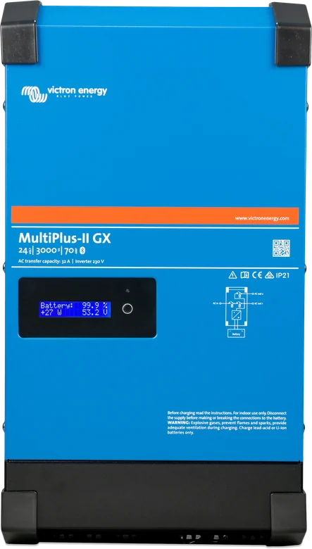
MultiPlus-II GX 24 V 3 kVA — front with GX display
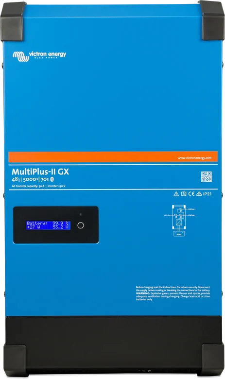
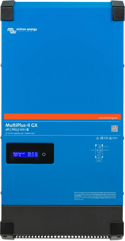
This is a MultiPlus-II with built-in GX device and a 2 × 16 character display. Without a separate Cerbo GX, it gives local system monitoring, VRM access via Ethernet or Wi-Fi, a VE.Direct port and a BMS-Can port for a compatible CAN-bus managed battery.
Inside is a standard MultiPlus-II: inverter, charger and transfer switch. The difference is the built-in GX card — backlit 2 × 16 character display, Ethernet socket and Wi-Fi. You can see the system locally and in the VRM portal, without adding a separate Cerbo GX.
The manufacturer intends it for grid-tied and off-grid energy storage and for backup power: when the grid disappears, the unit takes over the loads from the battery in a fraction of a second, and sends surplus from the panels to charging.
Shows PV power and voltage, state of charge, daily yield, battery state of charge and power, IP address, and AC input and output power — in a three-phase system separately for each phase.
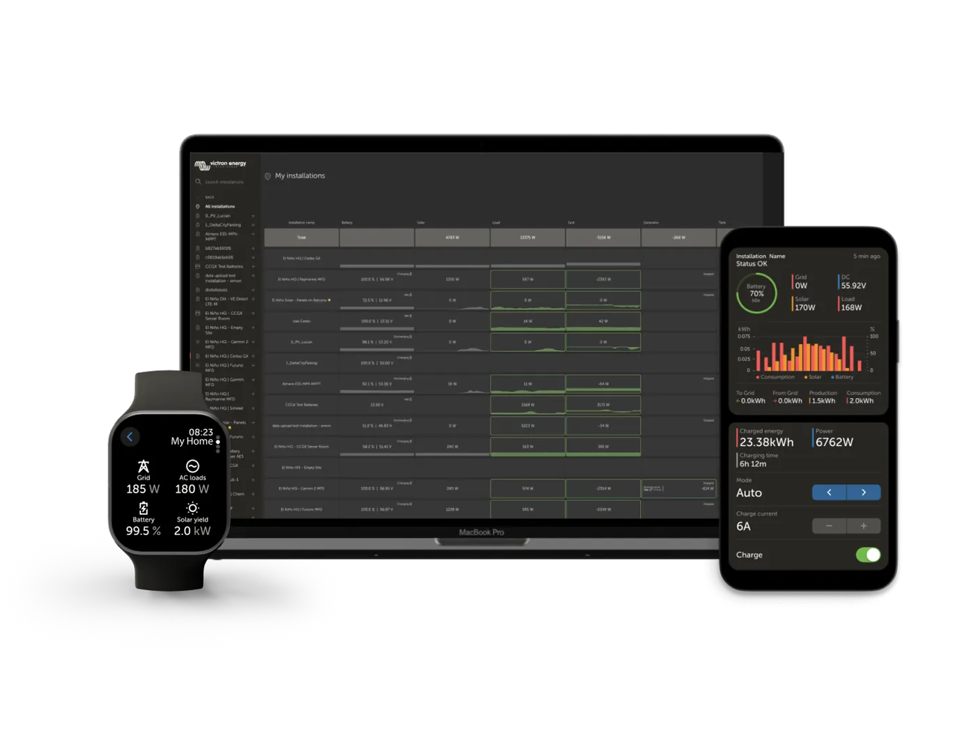
Local and remote monitoring via the VRM portal. Internet is required for the connection — the manufacturer recommends an Ethernet cable to the router; without a local network, the GX LTE modem remains.
For compatible batteries with a CAN-based BMS. This is not a VE.Can port — VE.Can MPPT solar charge controllers and VE.Can Lynx Shunt are not supported.
One VE.Direct port — for a SmartSolar solar charge controller or battery monitor; its data goes to the display and to VRM. The USB socket accepts, among other things, a memory stick with a GX card settings restore file.
Set the input current limit from shore power or a generator in the GX device, the app or on the Digital Multi Control panel. PowerAssist adds up to 3 kVA (13 A) from the battery — with a 32 A input, this gives up to 45 A at the output.
AC-out-1 works continuously. AC-out-2 disconnects the load when the unit switches to battery, and reconnects about 2 minutes after the input voltage returns — long enough for the generator to stabilise.
Programmable relay, for example for generator start, and two programmable analogue-digital ports — used, among other things, for the “allow to charge” and “allow to discharge” signals from a lithium battery BMS.
Controls the relay according to the set depth of discharge, voltage or load — with delay if you set it that way — and switches it off after the bulk phase ends.
Surplus from the grid-tie inverter on the AC output charges the battery. When there is no grid, the unit slightly raises the frequency to limit that inverter’s output (frequency shift).
Bulk – absorption – float – storage, with BatterySafe mode and shortened or extended absorption. The temperature sensor and Vsense wires compensate for voltage drop and battery heat.
Up to six identical units in parallel, in a three-phase star configuration (not delta). Only one GX device may operate in the whole system — that is why the manufacturer recommends models without built-in GX there.
To export energy to the grid, you must set the grid code in VEConfigure; changing the settings later requires a password from the distributor. When operating in parallel with the grid, current is measured by an external current transformer.
| Model | Continuous power at 25 °C | Peak | Max. charging at 25 °C | Transfer switch / AC input | Weight |
|---|---|---|---|---|---|
| 24/3000/70-32 GX | 3000 VA / 2400 W | 5500 W | 70 A | 32 A | 20 kg |
| 48/3000/35-32 GX | 3000 VA / 2400 W | 5500 W | 35 A | 32 A | 20 kg |
| 48/4k5/55-32 GX | 4 kW | 7 kW / 1 min | 55 A | 32 A | 21.4 kg |
| 48/5000/70-50 GX | 5000 VA / 4000 W | 9000 W | 70 A | 50 A | 31 kg |
| 48/6k5/100-50 GX | 6 kW | 11 kW / 1 min | 100 A | 50 A | 29 kg |
DC input: 19–33 V (24 V), 38–66 V (48/3000 and 48/5000), 38–60 V (4k5 and 6k5). Output 230 V ± 2%, 50 Hz. Charger input 187–265 V, 45–65 Hz. Auxiliary AC output AC-out-2 up to 32 A. For 48/4k5/55-32 GX at 40 °C the maximum charging current is 50 A, and for 48/6k5/100-50 GX — 95 A. Power decreases with temperature (for example, 48/5000: 3700 W at 40 °C, 3000 W at 65 °C). Ingress protection: IP22 for 24/3000, 48/3000 and 48/5000; IP21 for 48/4k5 and 48/6k5. Operating range: from −40 to +65 °C with fan cooling. Selected MultiPlus-II GX models are included in the Polish PTPiREE list of certificates — see home with energy storage.
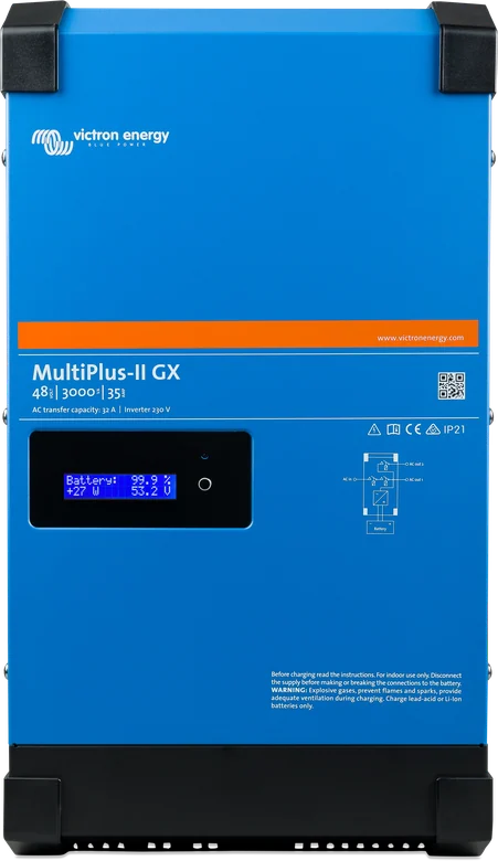
This is a MultiPlus-II with a built-in GX device: without a separate Cerbo GX it gives system monitoring and the VRM portal. In a parallel or three-phase system only one GX device can operate. Illustrative diagram.
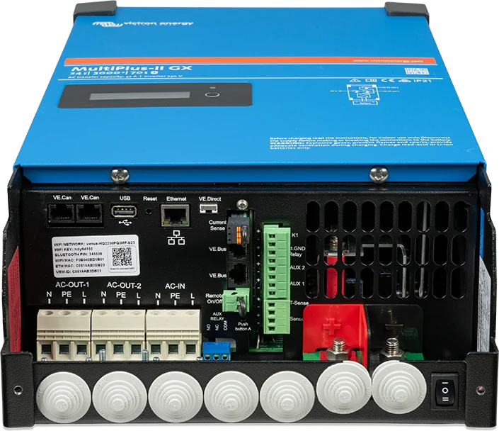
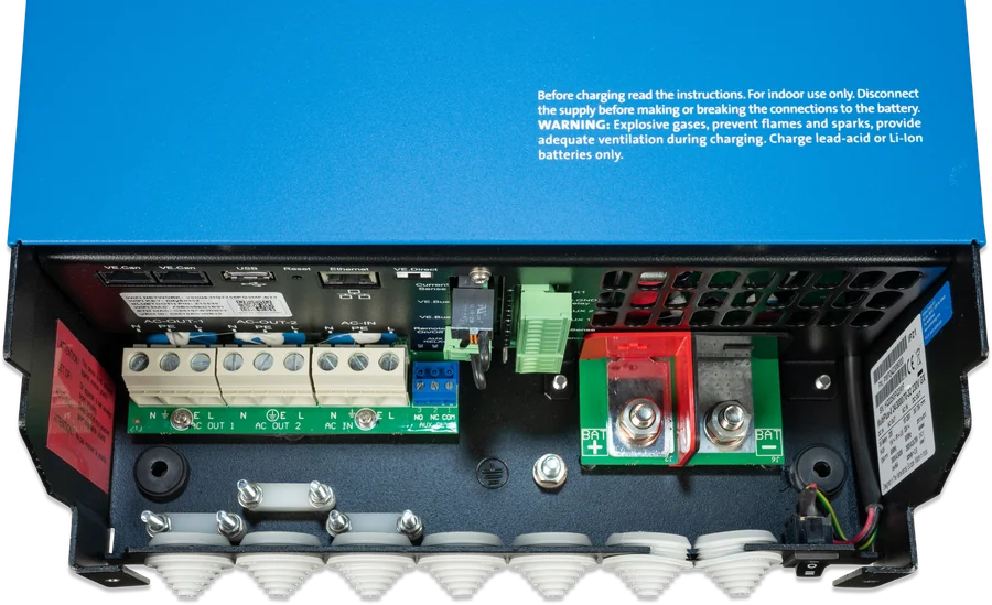
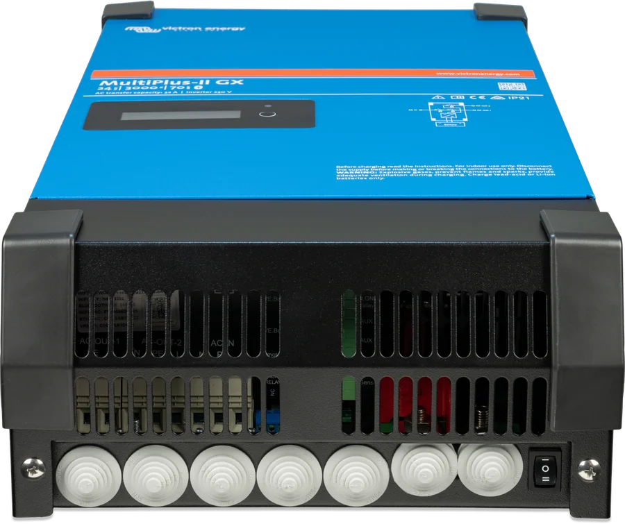
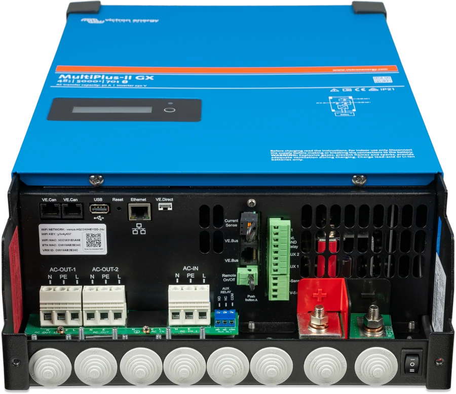
Inverter/charger with the GX card inside. Choose it when the system has one VE.Direct device and a battery communicating over BMS-Can, and you want one enclosure and a shorter cable list.
GX inside, 2 × 16 displayA separate GX centre provides VE.Can and BMS-Can ports, several VE.Direct inputs and a GX Touch touchscreen. It is also the only option for parallel and three-phase operation. Cerbo GX datasheet.
VE.Can + several VE.DirectMultiPlus-II, SmartSolar charge controller and GX device factory-connected in one enclosure — for when the panels are part of the project from the start. EasySolar-II GX datasheet.
MultiPlus-II + MPPT + GX| MultiPlus-II GX | MultiPlus-II + Cerbo GX | |
|---|---|---|
| Display | text display 2 × 16 characters | optional GX Touch 50/70 touchscreen |
| CAN ports | BMS-Can only (no VE.Can) | VE.Can and BMS-Can (both configurable in Cerbo GX MK2) |
| VE.Direct | 1 port | several ports (in Cerbo GX) |
| Installation | one device, fewer cables | separate GX module anywhere |
MultiPlus-II GX is suitable where one VE.Direct controller and a battery with BMS over BMS-Can are enough. For VE.Can devices (Lynx Smart BMS, VE.Can charge controllers) or several VE.Direct devices, a standard MultiPlus-II with Cerbo GX is a better choice.
The device operates at dangerous voltage and should be installed under the supervision of a suitably qualified person, in accordance with local regulations. Disconnect AC power and the battery before work.
The manual specifies for these models: 24/3000/70 — battery 200–700 Ah, 300 A fuse, 50 mm² at 0–5 m; 48/3000/35 — 100–400 Ah, 125 A, 35 mm²; 48/5000/70 — 200–800 Ah, 200 A, 70 mm². Copper cables with 90 °C insulation, at 5–10 m 95, 70 and 120 mm² respectively. For 48/4k5 and 48/6k5, check the data in the manual for those models.
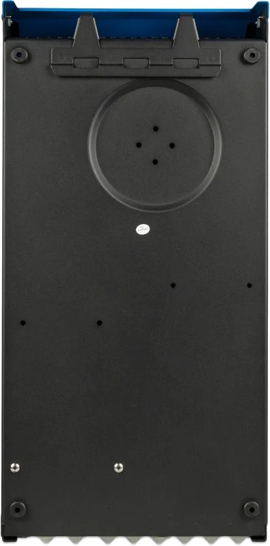
Dry, well ventilated and as close to the battery as possible — but never directly above it. Leave at least 10 cm of free space around the enclosure; too high an ambient temperature shortens the service life of the device, reduces charging current and peak power. Wall mounting: hook and two holes at the back, horizontal or vertical — vertical is better for cooling.
This is a Class I product — it must have a continuous earth connection. The internal earth relay connects the output N to the enclosure when there is no external supply, and opens before the input relay closes. The mains transformer inside eliminates DC components, so an RCD type A is sufficient. In a mobile installation the enclosure is connected to the chassis or hull, and on a boat an isolation transformer is used instead of direct shore earthing.
Inverter and charger settings are changed via the MK3-USB interface (VictronConnect or VEConfigure), and remotely via the GX card and VRM portal. With a Victron LiFePO4 battery with Lynx Smart BMS, set the remote mode to “Remote on/off”, and with smallBMS — “2-wire BMS”.
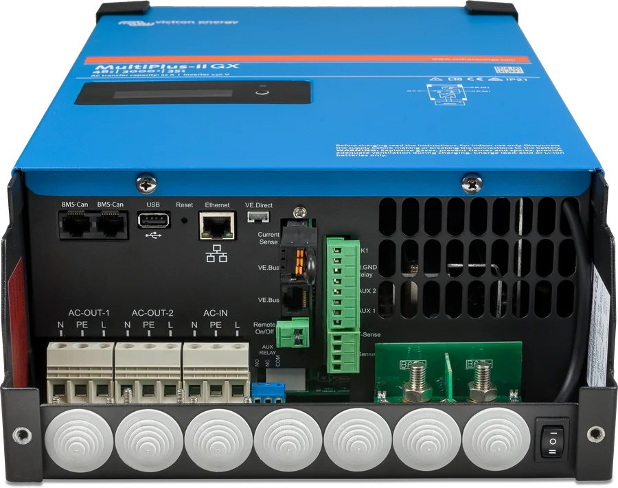
The GX card display shows inverter and charger messages, VE.Bus codes, and codes from the connected MPPT solar charge controller. The message stays on the screen until the cause disappears. We have collected the full list of VE.Bus codes in the VE.Bus error codes section.
The voltage has dropped below the threshold — if it falls further, the inverter switches off. Charge the battery or check the DC connections.
Clears automaticallyafter the battery has been charged.
The load exceeds the rated power; if the overload is large, the inverter stops working. Reduce the load.
Clears automaticallyafter the load is reduced.
The surroundings are too warm or the load is too high. Provide a cool, ventilated location and 10 cm clearance around the enclosure.
Clears itselfafter cooling down.
The battery is weak and the load is too high at the same time. Charge the battery, disconnect some loads, and consider a larger battery bank and shorter or thicker DC cables.
Ripple at the terminals exceeds 1.5 V RMS — usually because the battery cables are too thin or too long, connections are loose, or the battery bank capacity is too small.
The inverter has shut down due to ripple. Improve the DC wiring, increase battery capacity, and restart the unit with the switch.
Does not clear automaticallyrequires a restart.
Charging in bulk phase lasted for more than 10 hours, which may indicate a damaged cell. Check the battery; the error clears when the unit is switched off and on.
Does not clear automaticallyrequires a restart.
The unit is running from the battery — this output works only when AC is present on the input and returns with about a 2-minute delay. Also check the AC input fuse.
Clears automaticallywhen mains power returns.
Input voltage outside the 185–265 V range or frequency outside the set range (factory default 45–65 Hz), the AC input protection has tripped, or the battery fuse has blown. If the generator output voltage is distorted, enable WeakAC and the dynamic current limiter.
One of the other phases in the system has switched off. Check what happened on that phase.
The system has found fewer or more units than the configuration expects. Reconfigure the system, check the communication cables, switch everything off and on.
No other device was detected in the system — check the UTP cables between the units.
Excessively high voltage appeared at the output. Check the AC wiring.
This should not occur with a correct installation — check the communication cables.
Usually a short circuit in the communication cable — check the UTP cables.
Another device has taken over as “master” because the original one stopped responding. Check that unit and the cables.
This should not occur with a correct installation. Switch all devices off and on; if it returns, check the installation and consider raising the lower input voltage threshold to 210 V (factory default 180 V).
One of the devices has firmware that is too old. Switch the units on one by one until the error returns — update the last one you switched on.
This should not occur. Switch all devices off and on; if it repeats, contact the distributor.
Only by the built-in GX card with a 2 × 16 character display: you get system monitoring, the VRM portal via Ethernet or Wi-Fi, a VE.Direct port, USB, and a BMS-Can port. The inverter, charger, PowerControl and PowerAssist, two AC outputs and the ground relay work as in MultiPlus-II.
Up to six identical units can work in parallel, but there can be only one GX device in the system. To combine several GX models, you have to disconnect the internal connection of the GX card — that is why the manufacturer recommends models without built-in GX and a separate Cerbo GX in such setups.
No. BMS-Can (500 kbit/s) supports compatible batteries with a BMS communicating over CAN. According to the manual, VE.Can MPPT solar charge controllers and Lynx Shunt VE.Can are not supported. Connect the solar charge controller with a VE.Direct cable.
Only when AC is present on the input. When mains power fails, this output disconnects immediately, and when it returns, it comes back after about 2 minutes — so the generator has time to stabilise. AC-out-1 always works.
With a VE.Direct cable to the port in the connection compartment — the controller data then appears on the display and in the VRM portal. How to size the controller for the panels is described in the guide, and the MPPT calculator will calculate the string size.
It depends how you switch it off. The switch on the enclosure or the remote on/off terminals also turn off the GX card. Switching off from the Digital Multi Control panel, from the GX menu, or automatic shutdown after an alarm (low voltage, overheating) leaves the GX card on — data still goes to VRM.
The button next to the screen first increases the backlight (it turns off automatically after 5 minutes), and further presses scroll through the screens: panel power and voltage, daily yield, charge state, state of charge and battery power, IP address with connection type, and AC input and output power. In a three-phase system, readings for each phase are added.
Not in 48 V models — order it separately under part number ASS000001000. Fit the sensor to the negative battery terminal; it reduces the charge voltage as the battery warms up.
With the file venus-data-90-reset-all.tgz written to an empty USB flash drive formatted in FAT32 (do not unpack it or change its name). Turn the device off, insert the drive, turn it on, wait for the GX device to start, then remove the drive. The procedure requires Venus 2.12 firmware or later and deletes, among other things, a forgotten Remote Console password.
Yes, in an ESS system — but you must set the grid code in VEConfigure and meet the local grid-connection requirements. Any later change to parameters related to the grid code requires a password from the distributor. Selected MultiPlus-II GX models are listed in the Polish PTPiREE certificate register — see the house with energy storage wiring diagram for details.
Content checked against Victron Energy documentation (datasheets and manuals) — as of 19 September 2026. Report a content error · Revision log