
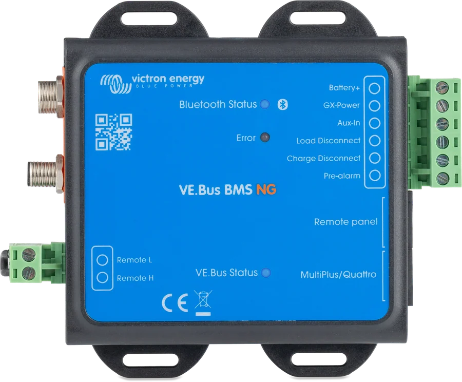
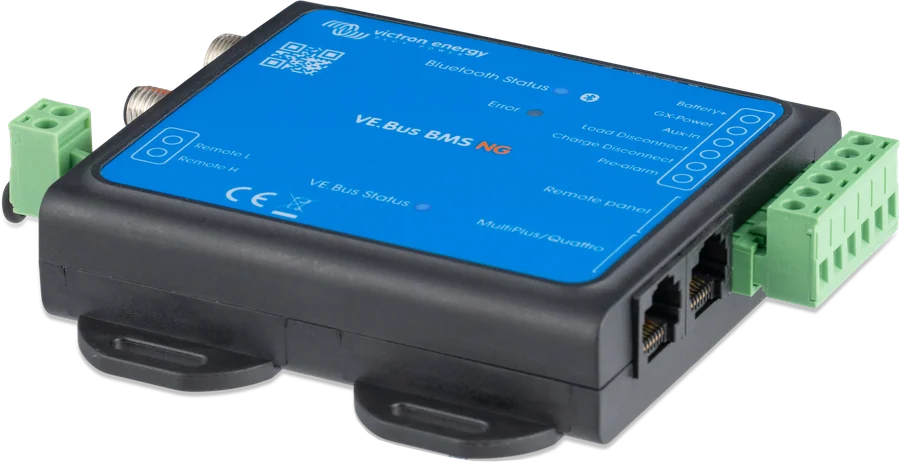
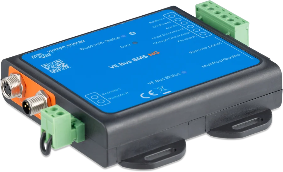
VE.Bus BMS NG — Bluetooth, Status, GX Power, Aux in, Load Disconnect, Charge Disconnect, Pre-alarm, Error LEDs and Remote L and H outputs
VE.Bus BMS NG
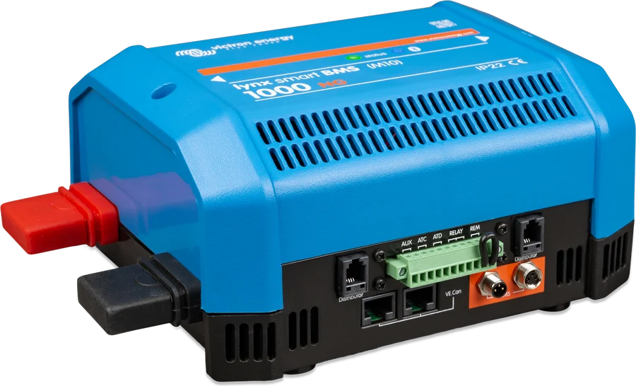
Battery management system Lithium NG in systems with a VE.Bus inverter or inverter/charger (MultiPlus, Quattro). It switches off inverter operation when cell voltage is too low and charging when voltage is too high or the temperature is wrong, and controls other chargers and loads via its outputs. It has Bluetooth and automatically detects connected batteries.
- 12 / 24 / 48 V
- up to 50 batteries (48 V: 25)
- VE.Bus
- Bluetooth
- Load / Charge disconnect, pre-alarm
BMS controlling MultiPlus via VE.Bus
- At too low cell voltage, it switches off the MultiPlus/Quattro inverter function (via VE.Bus) and the loads (Load disconnect output). At least 30 s earlier it activates the pre-alarm output.
- At cell overvoltage or incorrect temperature, it switches off charging for the MultiPlus/Quattro and other chargers (Charge disconnect output).
- Discharge floor — minimum SoC (10% factory setting) at which the BMS disconnects the loads controlled by the ATD output, leaving energy for self-discharge. Setting 0 disables this function — the manufacturer does not recommend it. The low SoC warning (and pre-alarm) appears at 12% by default.
- SoC on GX: unlike the VE.Bus BMS V2, it sends state of charge via VE.Bus — when “Battery monitor” is enabled in the MultiPlus/Quattro, GX shows SoC (other BMS parameters are not passed through).
- Capacity, voltage and number of batteries (series and parallel) are detected automatically — you cannot edit them, but you must check them. The VE.Bus BMS Assistant is no longer configured in VEConfigure.
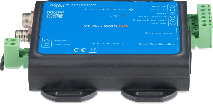
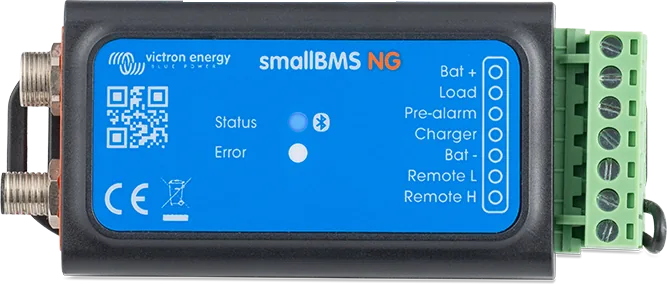
- The BMS has no negative terminal — it takes it from VE.Bus, so it needs a VE.Bus inverter or inverter/charger to operate (to start and read data without a connected Multi, it can be powered separately — the manual explains how). For systems without these, use the smallBMS NG.
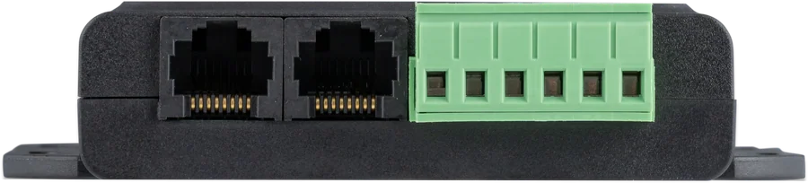
Outputs and inputs
| Terminal | Operation | What it is for |
|---|---|---|
| Load disconnect | normally high (approx. supply voltage − 1 V), floating when disconnected; up to 1 A | remote input for BatteryProtect, inverters, DC-DC converters; also sufficient for a high-power relay or contactor |
| Charge disconnect | normally high, floating when charging is disconnected; datasheet: 10 mA (500 mA in one section of the manual) | remote input for chargers (for example, Smart IP43), Cyrix-Li-Charge, Cyrix-Li-ct, BatteryProtect. Not for a relay coil or any other inductive load. |
| Pre-alarm | up to 1 A, no short-circuit protection | buzzer, lamp |
| GX-Pow (output), Aux-In (input) | 1 A each; GX-Pow from the battery or from Aux-In (higher voltage) | power supply for the GX device; an AC-DC power supply (min. 1 A at 12 V) on Aux-In will keep GX and VRM running after the system is switched off |
| Remote L / H | on: L–H shorted; L to negative (< 3.5 V); H between 2.9 V and battery voltage | system switch — a switch or factory loop required |
| 2 × RJ45 VE.Bus | “MultiPlus/Quattro” and “Remote panel” ports | inverter; GX device, DMC panel, VE.Bus Smart dongle |
AC chargers and smaller inverters are not yet controlled by GX — they need the Charge disconnect signal (ATC). VE.Bus inverters and Inverter Compact models from 1200 VA require the “inverting remote on-off” cable (ASS030550100 or -120), and SmartSolar up to 150/35 plus BlueSolar MPPT (except BlueSolar 150/70 and 150/80 CAN-bus) require the VE.Direct “non-inverting remote on-off” cable (ASS030550320). VE.Direct and VE.Can controllers on a GX device are controlled by DVCC, so they do not need BatteryProtect or Cyrix.
How to connect VE.Bus BMS NG
The BMS controls the MultiPlus or Quattro via VE.Bus, and the other devices via the Charge and Load disconnect outputs. It has no dedicated negative terminal — it takes it from VE.Bus. Schematic only.
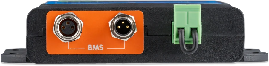
- BMS battery cablesChain; first and last cable to the BMS.
- Battery+ via 1 A fuseCable at least 0.75 mm², not included.
- RJ45 to inverter“MultiPlus/Quattro” port; VE.Bus software xxxx489 or later.
- GX deviceTo the “Remote panel” port, GX power from the GX-Pow output.
- Control outputsCharge and Load disconnect and pre-alarm for other devices.
Order and requirements
- BMS battery cables to the BMS (multiple batteries: chain, first and last cable to the BMS).
- Inverter DC cables to the battery.
- Battery positive via 1 A fuse to the “Battery+” terminal — cable not included: single-core, at least 0.75 mm².
- Inverter VE.Bus port to the “MultiPlus/Quattro” port with the supplied RJ45 cable.
- GX device: GX VE.Bus port to the “Remote panel” port, GX positive to GX-Pow, GX negative to the battery negative. Venus OS 2.80 or later required; enable DVCC.
- VE.Bus software of all inverters: xxxx489 or later. With versions from xxxx415, but lower than xxxx489, you must upload the VE.Bus BMS or ESS Assistant. Below xxxx415, VE.Bus error 15 appears — without an update, BMS NG will not work. Processors 19xxxxx and 20xxxxx are not supported.
- Grid detector (included) starts the inverter/charger when AC appears, if the BMS switched it off because of low cell voltage. It is not needed in the newer MultiPlus 12/1600/70 and 12/2000/80, MultiPlus-II, Quattro-II and inverters. In the other devices, one pair of AC wires is connected in the MultiPlus, both in the Quattro; in parallel and three-phase systems — only in the master device.
- The BMS must be connected to the battery positive — only then will it keep the MultiPlus in low-consumption mode even when AC is supplied.
- Chargers and loads not controlled by the BMS can permanently damage the battery. Installation must be carried out by qualified installers, in accordance with national safety regulations; before changing any connections, switch the system off and check for dangerous voltages. The manual also reminds you: do not open a lithium battery, do not mount it upside down, do not install it in a living area, provide ventilation, and do not discharge a new battery before its first full charge.
Currents and reserve after cut-off
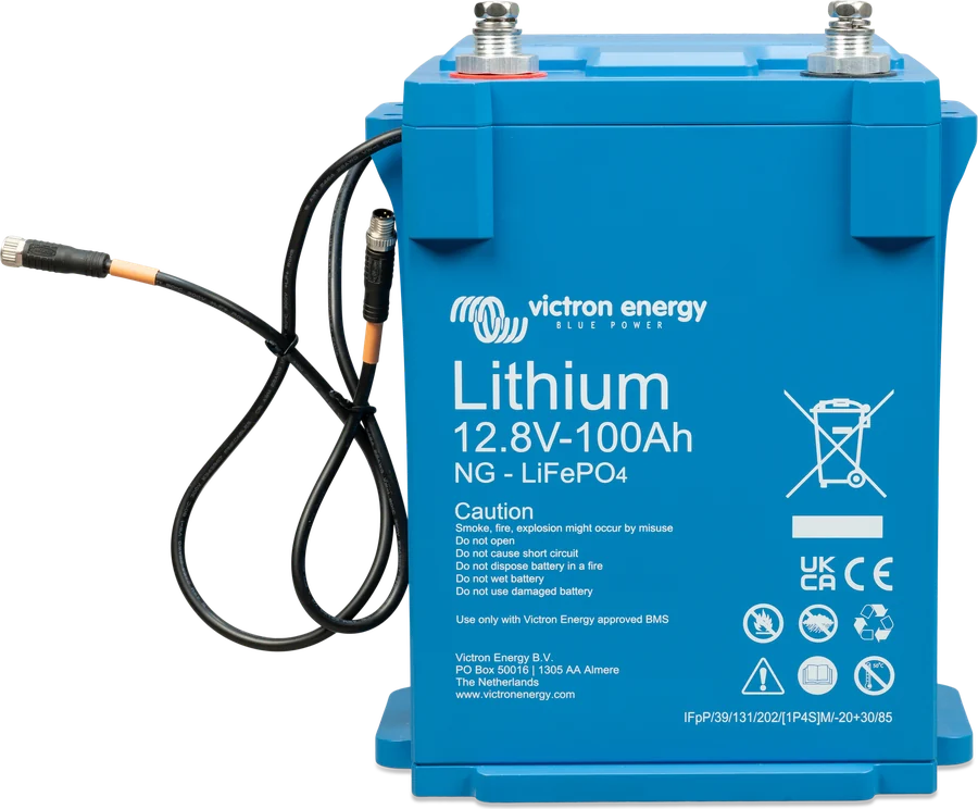
- Lithium NG batteries: max. continuous charge and discharge current 1C, recommended 0.3C when charging (according to the BMS manual; the Lithium NG battery manual itself recommends 0.5C) and 0.5C when discharging; discharge pulse 2C for up to 10 s.
- “Allowed to charge: No” appears, among other cases, when the battery temperature is below 5 °C or too high, when the cell has reached the high voltage threshold, or when remote is off.
- After cut-off due to low cell voltage, around 1 Ah remains for each 100 Ah of capacity. All remaining loads use this reserve — according to the manual, as little as 10 mA of residual current can damage a 200 Ah battery if the system remains discharged for more than 8 days. The battery must be charged immediately. The VE.Bus Smart dongle is not switched off by the BMS and can draw up to 9 mA.
- Tail current 4% and charge detection time 3 min (adjustable). If the system includes a Digital Multi Control panel and GX or dongle, the on/off/charger only switching works only with the DMC.
- The BMS does not set the charge voltages of solar charge controllers, Inverter RS, Multi RS or Multi — you must set these in the devices themselves (in ESS, the Multi does this according to the configuration).
Three LEDs
| Blue (Bluetooth) | on — connection; flashing — Bluetooth active without a connection; off — no power or Bluetooth off |
| Red | flashing — warning; on — alarm or error; off — no problem |
| VE.Bus | flash every 10 s — Multi on, BMS sending data; off — low power mode (Multi switched off by low cell voltage, remote or switch); fast flashing — bootloader (e.g. after an interrupted update) |
Codes in VictronConnect: W-/A-B01 low cell voltage, W-/A-B05 loss of communication with the battery (check the BMS cables), W-/A-B07 low SoC, A-B09 temperature too high for charging, A-B13 low temperature protection, E-B01/E-B05 incorrect battery configuration, E-B09 voltage out of range (below 9 V or above 60 V), E-B36 ATC/ATD fault, E-B11 hardware fault, E-B116 calibration lost, E-B119 settings lost. A warning announces shutdown, an alarm gives its cause. Full list of codes with descriptions and recommendations: smallBMS NG and VE.Bus BMS NG error codes — some numbers here mean something different from Lynx Smart BMS.
When the system will not start
- Inverter cannot find the BMS — it enters emergency mode: charges at up to 5 A to 12/24/48 V, with only the “mains on” LED lit. Without BMS confirmation of battery status, it will not start inverter operation after AC disconnect.
- Discharged or disconnected batteries — the Quattro must be powered via AC-in-1 (AC-in-2 will not start it). If charging does not start, connect a small battery charger (e.g. 5 A) and wait until the voltage returns to 12/24/48 V.
- Low cell voltage — the inverter goes into “charger only” mode, and without AC it is off. High cell voltage usually means imbalance — the inverter goes into bulk with reduced current so the cells can balance.
- Bluetooth off — switch the BMS off and on again; Bluetooth is active for about 30 s and can be enabled in VictronConnect.
- During a firmware update, the Charge disconnect output opens; after a failed update, Load disconnect also opens after 120 s.
General diagnostics: BMS has disconnected charging.
Most common questions about the VE.Bus BMS NG
Will the BMS work without a VE.Bus inverter?
Not in normal operation — the BMS has no separate negative terminal and takes it from VE.Bus, so it needs a VE.Bus inverter or inverter/charger. For start-up and reading data without a connected Multi, it can be powered separately; the manual describes how.
What software does the MultiPlus need?
VE.Bus xxxx489 or later. For versions from xxxx415, but below xxxx489, you need to load the VE.Bus BMS or ESS Assistant. Below xxxx415, VE.Bus error 15 will appear, and 19xxxxx and 20xxxxx processors are not supported.
Will GX show the state of charge?
Yes — unlike the VE.Bus BMS V2, the BMS NG sends the state of charge via VE.Bus. It is enough to enable the “Battery monitor” option in the MultiPlus or Quattro; other BMS parameters are not passed through.
What is discharge floor for?
It is the minimum state of charge (factory set at 10%) at which the BMS disconnects loads controlled by the ATD output, leaving energy for self-discharge. Setting it to 0 disables this function — the manufacturer does not recommend it.
Is a mains detector needed?
It is included and starts the inverter/charger when AC appears, if the BMS has switched it off because of low cell voltage. It is not needed in the newer MultiPlus 12/1600/70 and 12/2000/80, MultiPlus-II, Quattro-II and inverters.
Manufacturer documentation
Content checked against Victron Energy documentation (datasheets and manuals) — as of 19 September 2026. Report a content error · Revision log