Error 2
Battery voltage too high
The DC terminal voltage has exceeded the permitted level — the inverter stops operating until it drops.
Clears automaticallyonce the voltage drops.
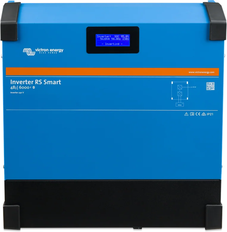
Inverter RS Smart 48|6000 — front with LCD display, version without solar input
Inverter for a 48 V battery bank. It produces a pure 230 V sine wave. You configure it via Bluetooth in VictronConnect. Use the VE.Can port for the GX device. On the AC output you can connect an external grid-synchronised PV inverter and charge the battery; the PV inverter must respond to a rise in frequency by reducing power. For AC coupling, follow the 1:1 rule, the minimum battery requirements and the Victron AC Coupling manual. The manual applies to model PIN482600000.
Inverter RS Smart works with a 48 V battery bank and provides a pure 230 V sine wave: 25 A continuous output current, and at 25 °C from 4600 to 5200 W continuous power according to the manual (the datasheet states 4800–5300 W — design to the lower value).
This is the inverter only: it has no mains charger and no panel input. You charge the battery from an external PV inverter connected to the AC output circuit — AC coupling. The maximum charge power from this source is 5000 W, and the algorithm is the same as in BlueSolar MPPT controllers: bulk, absorption, float.

25 A continuously, 9 kW for 3 seconds and 7 kW for 4 minutes according to the datasheet. Output voltage adjustable from 210–245 V, frequency 50 or 60 Hz.
An external PV inverter on the AC output circuit charges the battery at up to 5000 W. At absorption voltage, current is limited by increasing frequency; the PV inverter stop frequency is 53.2 Hz and cannot be changed.
Backlit LCD with four lines: battery levels, solar yield and system icons — no phone and no GX device.
Configuration and monitoring via Bluetooth; the default PIN code is on the product label. On Windows you need a VE.Direct to USB interface.
Monitoring, energy meter, data logging and remote updates. The VE.Direct port is not for GX — you can connect only a GlobalLink 520 to it.
Up to 12 units, three-phase system from three units, maximum 4 per phase and the same number on each phase. The whole system must work on one battery bank; mixing with Multi RS is not supported.
Normal, High and LiFePO4 2-wire BMS. Absorption is 57.6 V by default, float 55.2 V, charger range 36–60 V — all adjustable.
Enabled by default: connects N to PE when the inverter is running. The enclosure requires earthing (protective class I), and type A residual current protection can be used on the output.
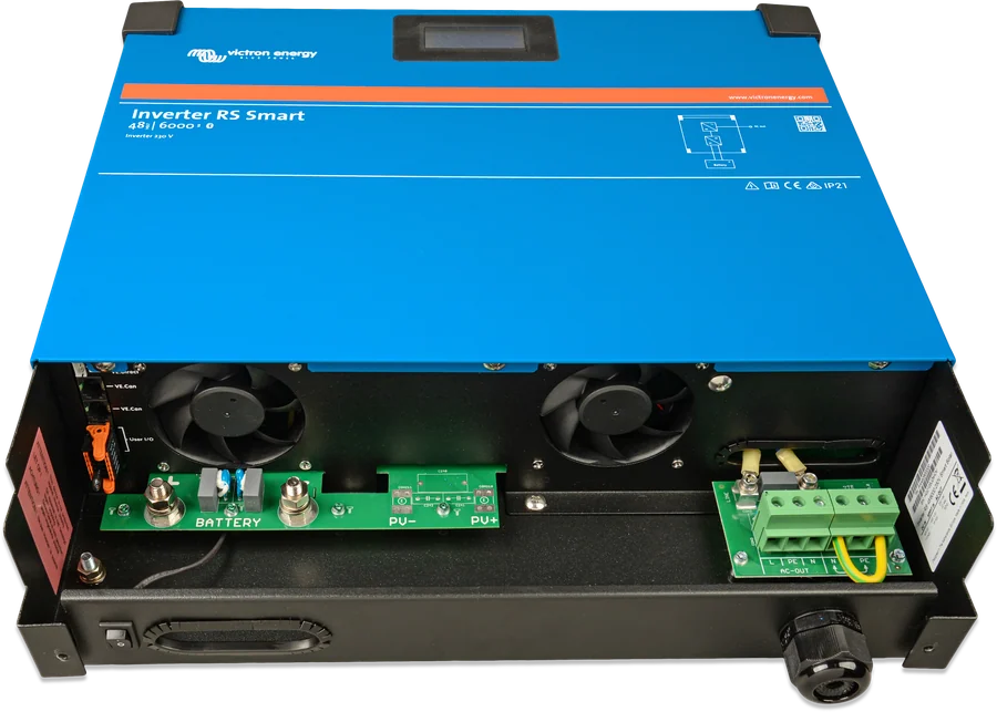
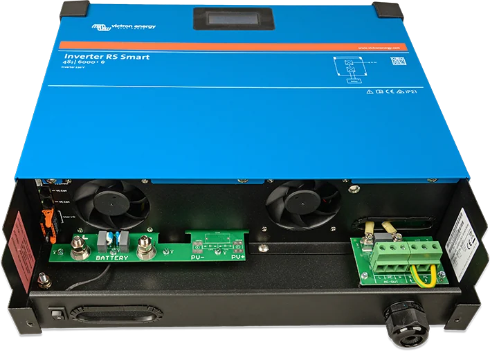
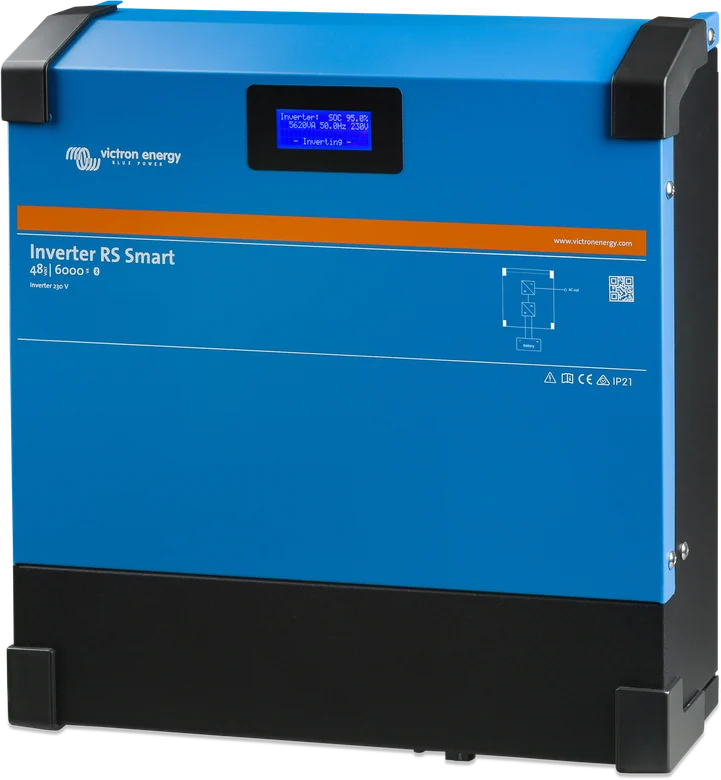
The values below are taken from the datasheet and Rev. 07 manual. Where the sources differ, both figures are given.
| Parameter | Value |
|---|---|
| DC input voltage range | 38–62 V |
| Minimum start-up voltage | 41 V |
| Disconnect at overvoltage | 65.5 V |
| Low battery voltage cut-off | 37.2 V by default (adjustable) |
| Reconnect after low voltage | 43.6 V by default (adjustable) |
| Output voltage | 230 V AC ± 2%; setting 210–245 V |
| Output frequency | 50 Hz ± 0.1%; 50 Hz or 60 Hz selection |
| Maximum continuous inverter current | 25 A AC |
| Continuous power at 25 °C | Datasheet: rises linearly from 4800 W at 46 V DC to 5300 W at 52 V DC. Rev. 07 manual: from 4600 W to 5200 W. Use the lower value. |
| Continuous power at 40 °C | 4500 W |
| Continuous power at 65 °C | 3000 W |
| Peak power | Data sheet: 9 kW for 3 s and 7 kW for 4 min. Manual: maximum 9,000 W or 50 A AC for 3 s. |
| Short-circuit output current | Data sheet: 50 A. Manual: 45 A. Use 45 A. |
| Max. AC output overcurrent protection | 30 A |
| Efficiency | 96.5% at 1 kW; 94% at 5 kW |
| No-load consumption | 20 W |
| Absorption voltage | default 57.6 V (adjustable) |
| Float voltage | default 55.2 V (adjustable) |
| Charger voltage range | 36–60 V |
| Max. charging power from AC-coupled PV | 5000 W |
| Maximum charging current | In tables: 88 A at 57.6 V. In the manual description: 100 A limit, reduced when battery voltage exceeds 60 V. |
| Parallel and 3-phase operation | 12 units in parallel; 4 units per phase |
| Communication | VE.Direct, VE.Can, Bluetooth (2402–2480 MHz, 4 dBm) |
| Enclosure | steel, blue RAL 5012; IP21; 11 kg; 425 × 440 × 125 mm |
| Operating temperature | Specification: −40 to +65 °C (fan cooling). Installation environment: −40 to 60 °C. |
| Altitude and humidity | max. 2,000 m; max. 95% non-condensing |
| Overvoltage category | battery OVC I, AC output OVC II |
Overview diagram: 48 V battery, inverter and 230 V output. Hover over or tap an element to see the description.
A 48 V inverter only. Panels connect to a separate PV inverter on the 230 V side (AC coupling), and charging from this source reaches 5,000 W and about 98% SoC.
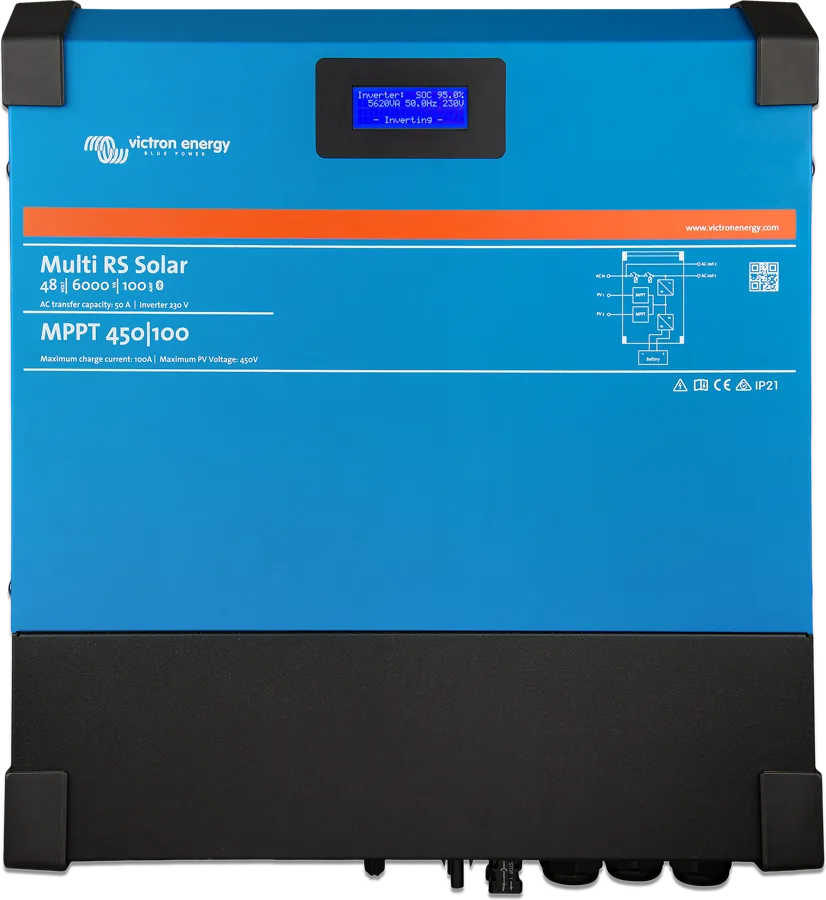
without MPPT · without AC chargerThe same inverter with a built-in 450 V MPPT charge controller — panels connect directly via MC4 connectors. The current data sheet shows two 3 kW inputs; the manufacturer also describes a version with a single 4 kW tracker. Inverter RS Smart Solar data sheet.
450 V MPPT insideAlso has AC input from the grid or a generator and a charger — the unit switches sources and charges the battery even without sun. Multi RS Solar data sheet.
2 × 450 V MPPT + charger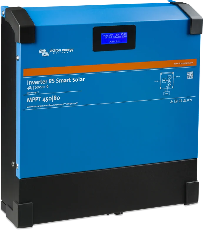
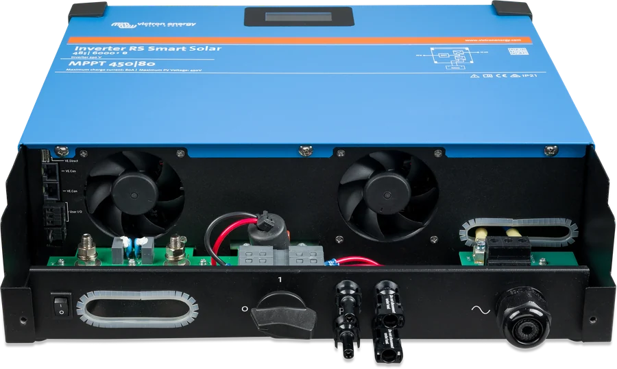
The inside can contain 400–500 V DC even when the unit is switched off. Before working, disconnect all power sources and wait at least 5 minutes. Use insulated tools only. Do not touch uninsulated cable ends.
| Length | Min. cross-section per + and − terminal | Recommended DC fuse |
|---|---|---|
| 0–2 m | 35 mm² | 125 A |
| 2–5 m | 70 mm² | 200 A |
In a parallel system, the AC wiring from the inverters to the common output point must be symmetrical. Connect all units daisy-chained with a VE.Can cable (RJ45 cat5 / cat5e / cat6) with terminators at both ends. In parallel and 3-phase systems, each unit must have individual AC and DC protection; use the same fuse type for each unit.
The display shows inverter status, power, frequency and AC voltage. The Bluetooth icon changes colour when connected, and flashing means an error or warning. The battery icon fill corresponds to voltage; the icon flashes when the battery is empty.
Short circuit on the output, overload, too high or too low battery voltage, too high temperature, 230 V AC on the inverter output, and solar leakage current. In the manual, the table may be marked a–f; the key and the datasheet also include item g.
The DC terminal voltage has exceeded the permitted level — the inverter stops operating until it drops.
Clears automaticallyonce the voltage drops.
The battery temperature sensor is not responding or is faulty. Check the cable and its mounting on the battery negative terminal.
Ripple at the battery terminals is too high. This usually means loose connections or DC cables that are too thin.
Charging of the LiFePO4 battery is stopped until the temperature returns to the permitted range.
Clears automaticallyafter the battery warms up.
The terminals are heating above the permitted temperature. Check the wiring: cable cross-section, tightness and condition of the lugs.
The inverter shuts down when the voltage difference between neutral and protective earth (N–PE) is too large.
Continuous power or peak current on the AC output has been exceeded. Reduce the load and restart the inverter.
The electronics have exceeded the permitted temperature. Provide a cool, ventilated location and clearance around the enclosure.
Clears itselfafter cooling down.
There is already AC voltage from another source on the AC output when the inverter is switched on. Check the installation and restart the unit with the power switch.
Does not clear automaticallyrequires a restart.
In a parallel system, one of the units has stopped responding. Check the VE.Can wiring and terminators.
The charger is controlled by the BMS, but it is not receiving messages, so it stops charging. Check the connection to the battery BMS.
The system configuration (parallel or 3-phase) does not match the actual arrangement of units.
The units have different firmware versions. All of them report error 71 until you update them to the same version.
The controller processor has exceeded the permitted temperature.
Clears automaticallyafter cooling down.
The device cannot read its own configuration and stops operating — reconfiguration is required.
Does not clear itself
If the current limit is exceeded continuously, the inverter shuts down for 30 s and restarts automatically. After three such restarts within 30 s of start-up, it remains off — disconnect the load, switch it off and on again.
After switching off, the inverter waits at least 30 s and starts when the voltage exceeds the restart threshold. After three cycles within 30 s of start-up, it stops making further attempts — switch it off and on again.
The unit waits 30 s and resumes operation when the voltage drops to the permitted level.
The inverter restarts after 30 s and does not stop trying — unlike overload and low voltage, it does not remain off after several attempts.
This error does not clear automatically. Check the installation and restart the unit with the power switch.
Usually loose connections or DC cables that are too thin — check the terminal tightness and cable cross-section.
Efficiency drops, alarms and shutdowns occur, and in extreme cases permanent damage may result.
This shortens the service life of the device, reduces charging current and peak power, and if the temperature keeps rising, the inverter shuts down.
If the problem persists, contact the dealer or installer from whom you bought the unit. The product has a 5-year limited warranty.
No. You cannot use the VE.Direct port for a GX device. VE.Can is used for GX devices, for example Cerbo GX. VE.Direct is used to connect to the GlobalLink 520.
No. Charging from AC PV reaches about 98% SoC. The unit does not allow a full 100% charge from the AC PV inverter.
No. Smart Battery Sense and other VE.Smart Network features are not currently supported.
You can use a type A residual current device. You must earth the enclosure (protection class I).
Mixing Inverter RS with Multi RS is not currently supported.
Lead-acid: 200 Ah. Lithium: 50 Ah.
The default PIN code is on the product information sticker. If VictronConnect does not connect over Bluetooth, see Bluetooth diagnostics.
Content checked against Victron Energy documentation (datasheets and manuals) — as of 19 September 2026. Report a content error · Revision log