
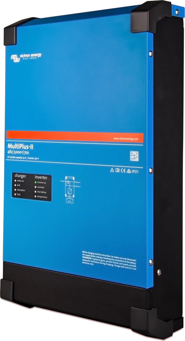
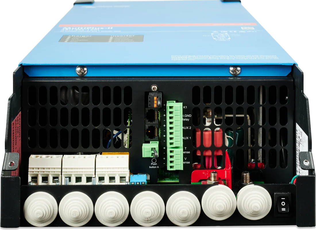
MultiPlus-II 48 V 5 kVA — side view
MultiPlus-II
A pure sine wave inverter, battery charger and automatic transfer switch in one enclosure. The heart of most Victron systems — from a campervan to a home energy storage system.
- 12 / 24 / 48 V DC
- 3–15 kVA
- 230 V · 50 Hz
- switch-over < 20 ms
- IP22
Three devices in one housing
The inverter converts DC from the battery into 230 V pure sine wave AC — as “clean” as from a socket, so you can power electronics, a fridge, a coffee machine or tools with it.
The charger charges the battery as soon as external power is available: campsite hook-up, shore power, generator or mains at home. The standard algorithm is a four-stage adaptive charge with BatterySafe, recommended for lead-acid batteries; for other types, including lithium-ion, charge parameters must be configured according to the battery documentation.
The transfer switch automatically switches loads from mains to battery and back again. It does this in less than 20 ms, so computers and controllers do not notice the power failure — MultiPlus-II works like a UPS.
- Campervans and vans — the 12 V 3 kVA model is enough for a kettle or coffee machine.
- Yachts — shore power with PowerAssist when the shore connection is weak.
- Home energy storage (ESS) — most often 48 V versions; ESS also works at 24 V, with only the 12/3000/120-32 model as an exception.
- Off-grid installations — with a generator as a backup source.
- Special vehicles — quiet operation of appliances without starting the engine.
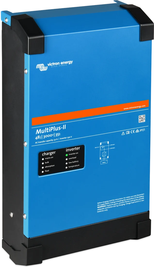

What MultiPlus-II can do
UPS function
After a mains failure or disconnection of the hook-up, it takes over the loads in less than 20 ms. Computers and electronics keep running without interruption.
PowerControl
You set the maximum current drawn from the mains or generator. When loads approach the limit, MultiPlus-II automatically reduces the battery charge current.
PowerAssist
When the shore power is not enough — for example weak campsite hook-up — it adds the missing power from the battery. When the load drops, it uses the surplus for charging.
Two AC outputs
AC-out-1 always works. AC-out-2 is active only when external power is available — connect loads here that should not discharge the battery, for example a water heater. When AC-in power returns, it switches the load on after about 2 minutes.
ESS — energy storage system
Together with a GX device, it works as a home battery storage system: it increases self-consumption from solar PV and powers selected circuits during a grid failure. It has built-in anti-islanding protection.
Expansion
You can connect up to 6 identical units in parallel and build 3-phase systems from three identical models. In grid-connected installations, you cannot connect units in a system above 30 kW at one connection point. The 8, 10 and 15 kVA models can be connected in parallel only with an external AC switch.
Adaptive charger
Bulk – absorption – float – storage with BatterySafe mode: after shallow discharge, absorption is shorter; after deep discharge, longer (up to 8 hours). In storage mode the voltage drops to 2.2 V per cell, and once a week it returns to absorption level.
Relay, Vsense and temperature sensor
Programmable relay (alarm by default, can be set, for example, for generator start), two 0.75 mm² Vsense wires measuring voltage directly at the battery (compensation up to 1 V) and a temperature sensor — included except with 48 V models.
External current transformer
In parallel operation with the grid, the internal current transformer will not measure grid current — an external sensor is needed. It also extends PowerControl and PowerAssist to 50 A (3 kVA) and 100 A (5 kVA).
Thirteen 230 V models
| Model | Battery | Continuous power at 25 °C | Peak power | Charge current | AC switch | Weight |
|---|---|---|---|---|---|---|
| 3 kVA | ||||||
| 12/3000/120-32 | 12 V | 3000 VA · 2400 W | 5500 W | 120 A | 32 A | 19 kg |
| 24/3000/70-32 | 24 V | 3000 VA · 2400 W | 5500 W | 70 A | 32 A | 19 kg |
| 48/3000/35-32 | 48 V | 3000 VA · 2400 W | 5500 W | 35 A | 32 A | 19 kg |
| 5 kVA | ||||||
| 12/5000/220-50 | 12 V | 5000 VA · 4000 W | 9000 W | 220 A | 50 A | 33 kg |
| 24/5000/120-50 | 24 V | 5000 VA · 4000 W | 9000 W | 120 A | 50 A | 30 kg |
| 48/5000/70-50 | 48 V | 5000 VA · 4000 W | 9000 W | 70 A | 50 A | 30 kg |
| 8–15 kVA (48 V only) | ||||||
| 48/8000/110-100 | 48 V | 8000 VA · 6400 W | 15 000 W | 110 A | 100 A | 42 kg |
| 48/10000/140-100 | 48 V | 10,000 VA · 8000 W | 18 000 W | 140 A | 100 A | 49 kg |
| 48/15000/200-100 | 48 V | 15,000 VA · 12,000 W | 27 000 W | 200 A | 100 A | 80 kg |
| New series: 4k, 4k5, 6k5 and 10k (separate datasheet) | ||||||
| 12/4k/160-32 | 12 V | 3400 W | 6000 W (2 s) | 160 A | 32 A | 22 kg |
| 48/4k5/55-32 | 48 V | 4000 W | 7000 W (1 min) | 55 A | 32 A | 22 kg |
| 48/6k5/100-50 | 48 V | 6000 W | 11,000 W (1 min) | 100 A | 50 A | 29 kg |
| 48/10k/150-100 | 48 V | 10 000 W | 15,000 W (2 min) | 150 A | 100 A | 48 kg |
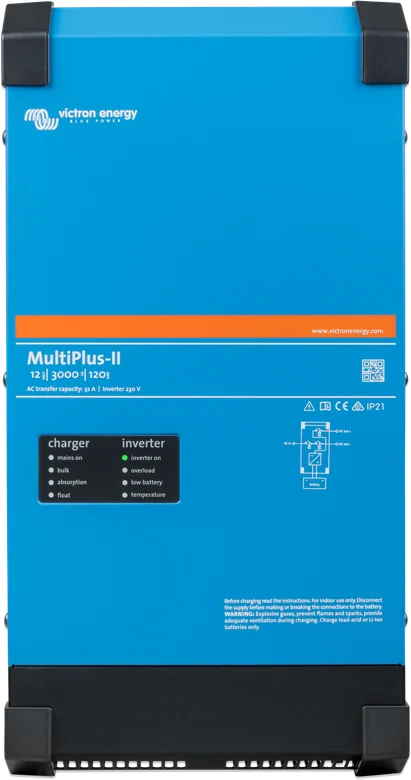
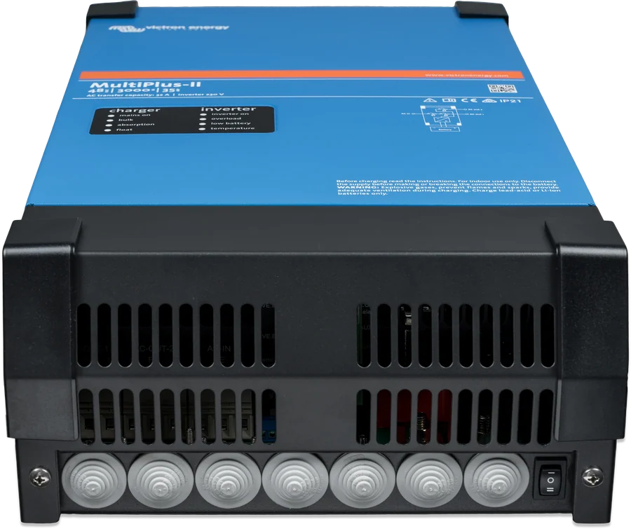
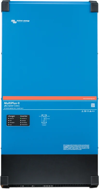
How to read the name: 24/3000/70-32 = 24 V battery / 3000 VA output / 70 A charge current / 32 A AC switch. Continuous power drops with ambient temperature — for example, the 3 kVA model delivers 2400 W at 25 °C, 2200 W at 40 °C and 1700 W at 65 °C. In the new series, the datasheet gives continuous power in kW and peak power together with its duration. There are also 120 V versions for the American market.
- Output voltage
- 230 V ±2%, 50 Hz (60 Hz possible)
- Charger AC input
- 187–265 V, 45–65 Hz
- DC voltage range
- 9.5–17 / 19–33 / 38–66 V
- Absorption / float (default)
- 14.4 / 13.8 V (for 12 V)
- Maximum efficiency
- 93–96%
- Search mode consumption
- 2–6 W (new series 4–8 W)
- Operating temperature
- −40 … +65 °C
- Enclosure
- steel, IP22 (new series IP21)
- Programmable relay
- yes (alarm, generator start)
- Battery temperature sensor
- included, except with 48 V models
MultiPlus-II 4k5 and 6k5 — more power per kilogram
The manufacturer describes the new models with the phrase “more power per kilogram and per litre, better performance at high temperature”. The 48/4k5/55-32 model weighs 22 kg (590 × 275 × 149 mm), and the 48/6k5/100-50 model weighs 29 kg (644 × 320 × 150 mm). For comparison, the 48/5000/70-50 from the older series weighs 30 kg.
In the 4k5 and 6k5 models, the number in the name refers to short-term power at cold start, not continuous power: 4k5 provides 4.5 kW for 2 hours, 6k5 — 6.5 kW for 4 hours. Continuous output at 25 °C is 4 kW and 6 kW respectively.
- Short-term power 2: 4k5 — 6 kW for 25 min, 6k5 — 8 kW for 1 h; peak 7 kW and 11 kW for 1 min.
- Charging 55 A and 100 A at 25 °C, 50 A and 95 A at 40 °C; absorption 57.6 V, float 55.2 V.
- AC input 32 A (4k5) and 50 A (6k5) — this is also the factory limit for PowerControl and PowerAssist. In a parallel system with the grid, with an external 100 A current transformer, the range increases to 50 A (4k5) and 100 A (6k5).
- Enclosure steel IP21, operating from −40 to +65 °C, up to 4000 m above sea level with a 1% power reduction for every 100 m above 2000 m.
- Battery temperature sensor is optional in 48 V models (ASS000001000); included in 12/4k.


| New series | DC fuse | Cable 0–5 m | Cable 5–10 m | Battery capacity | AC-out-2 |
|---|---|---|---|---|---|
| 12/4k/160-32 | 600 A | 2 × 70 mm² | 2 × 95 mm² | 400–1200 Ah | 32 A |
| 48/4k5/55-32 | 180 A | 50 mm² | 70 mm² | 200–800 Ah | 32 A |
| 48/6k5/100-50 | 250 A | 70 mm² | 95 mm² | 250–1200 Ah | 32 A |
| 48/10k/150-100 | 400 A | 2 × 50 mm² | 2 × 70 mm² | 250–1200 Ah | 50 A |
Cross-section per pole, “2×” means two positive and two negative cables. Copper cables with 90 °C insulation, not in a closed conduit. Data from the “MultiPlus-II 4k, 4k5, 6k5, 10k 230V” manual; electrical data from the datasheet for this series. The datasheet and the manual differ in a few places: 12/4k — peak power 6 kW for 2 s (datasheet) or 30 s (manual) and short-term power 4.5 kW for 30 min (datasheet) or 2 s (manual); 10k — efficiency 95% (datasheet) or 93% and AC input 187–265 V (datasheet) or 187–250 V (manual). In the tables we give the datasheet values.
Where the MultiPlus-II sits in the system
Simplified layout of a campervan, yacht or cabin. Hover over or tap a diagram element to see the description.
- Mains / generator → AC-inExternal power supply. You set the input current limit in the MultiPlus-II.
- MultiPlus-IITransfers mains power to the loads and charges the battery, or produces 230 V from the battery.
- AC-out-1 → 230 V loadsAlways active — from the mains or from the battery.
- AC-out-2 → water heaterOnly when external power is available, so as not to discharge the battery.
- Battery + MPPTShared energy storage charged from the mains and from panels.
- Cerbo GX (VE.Bus)Monitoring, control and remote access via VRM.
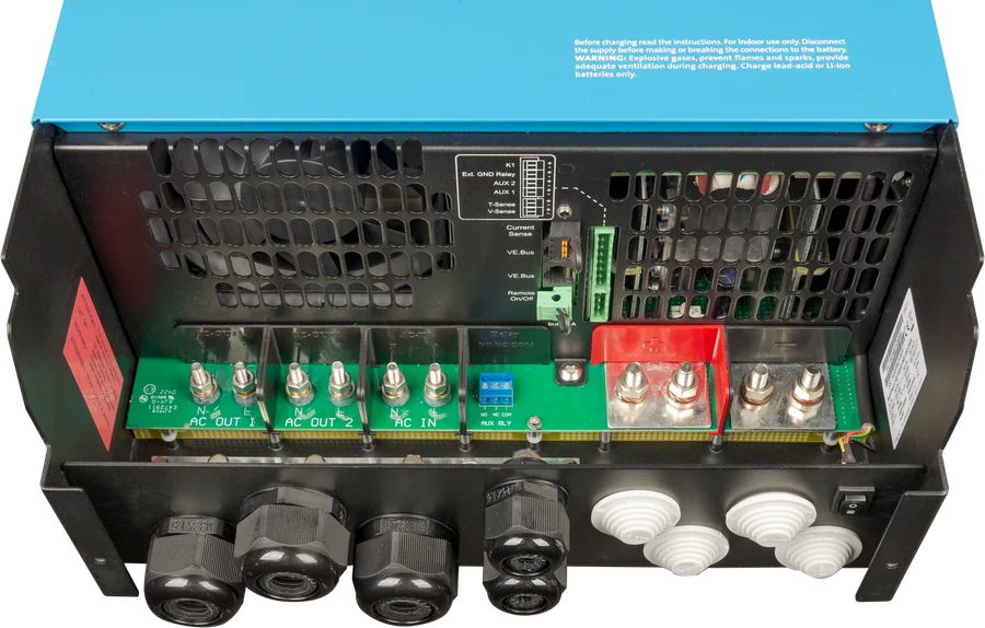
What is under the service cover
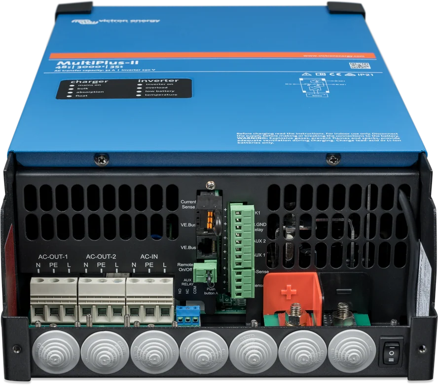
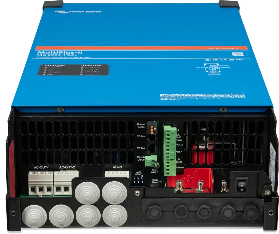
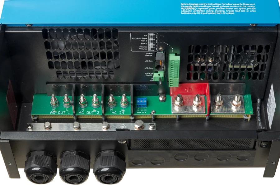
- AC terminal strips — terminal order from the left: N (neutral), PE (protective earth), L (line). Do not swap N and L. Torque on the AC-out-2 terminals: max. 2 Nm.
- AC input protection — circuit breaker no greater than 32 A (3 kVA models), 50 A (5 kVA) or 100 A (8, 10 and 15 kVA); in the new series the maximum input current is 32 A (4k, 4k5), 50 A (6k5) and 100 A (10k). If the source has a lower rating, choose a smaller one.
- AC-out-1 output — PowerAssist adds up to 3 kVA, i.e. 13 A, so with a 32 A input you can draw up to 45 A from the output. Overcurrent protection and RCD are selected for this value.
- Battery terminals — M8 bolts, 12 Nm torque, torque wrench with insulated socket. AC screws: M4 — 1 Nm, M5 — 3 Nm, M6 — 5.5 Nm; in the new 4k–6k5 series, 13 mm² screw terminals, 2 Nm torque.
- Vsense — two 0.75 mm² wires measure the voltage directly at the battery; the charger will compensate for a voltage drop of up to 1 V per terminal, and with a larger drop it will reduce the charging current.
- Remote control — a simple switch on the “remote on/off” terminals or a Digital Multi Control panel in the RJ45 socket; it works only when the switch on the unit is in the “on” position.
Choosing the model in practice
12 V · 3 kVA or 4k
Kettle, coffee machine or microwave (2.4 kW continuously, and in the new 12/4k — 3.4 kW). At 2 kW, around 170–190 A flows from a 12 V battery — the cables and battery must be able to handle it.
12/3000/120-32 · 12/4k/160-3224 V · 3 or 5 kVA
Higher voltage means half the current compared with 12 V: thinner cables and lower losses. The 5 kVA model is suitable for air conditioning or induction cooking.
24/3000/70-32 · 24/5000/120-5048 V · 4k5–15 kVA
Standard in energy storage systems. The lighter 4k5 and 6k5 models in the new series provide 4 and 6 kW of continuous power. For higher power, units are connected in parallel or in a three-phase system.
48/4k5/55-32 · 48/6k5/100-50 · 48/10000/140-100When another device will be better
| MultiPlus-II | Quattro-II | MultiPlus-II GX | Phoenix Inverter Smart | |
|---|---|---|---|---|
| 230 V inverter | yes | yes | yes | yes |
| Mains / generator charger | yes | yes | yes | no |
| AC inputs | 1 | 2 (mains + generator) | 1 | — |
| UPS function | yes | yes | yes | no |
| Built-in GX centre | no | no | yes | no |
| When to choose | most systems | two AC sources without a changeover switch | fewer devices and cables | only 230 V from the battery |
What to watch out for
Residual current protection, earthing and connection to the home mains should be carried out by a qualified person. Before working on the MultiPlus-II, disconnect the AC supply and the battery; dangerous voltage may still be present at the terminals even after the unit has been switched off. The MultiPlus-II has an internal earthing relay which connects N to PE in inverter mode — this must be taken into account when selecting protection devices.
There must be a fuse and disconnect switch between the battery and the MultiPlus-II. Take the cable cross-sections and fuse ratings from the manual for the specific model — at 12 V, currents reach several hundred amperes.
Settings are changed via the MK3-USB interface and the VictronConnect app or VEConfigure software. Via Bluetooth: the VE.Bus Smart dongle (Bluetooth) lets you monitor the unit, switch it on and off, and change the AC input current limit — to change settings you need the MK3-USB interface. Remotely — via the GX centre and the VRM portal.
Set the absorption and float voltages according to the battery type. Lithium batteries require a BMS compatible with the system. For Victron Lithium Smart, use VE.Bus BMS V2 or Lynx Smart BMS. Install and configure other lithium batteries in accordance with the list of compatible Victron battery types and the installation and configuration manual.
The enclosure is not waterproof. Install in a dry, well-ventilated place, with clear space for fan cooling.
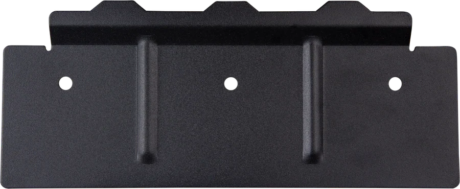
- Location: dry and well ventilated, as close to the battery as possible, but never directly above it. The mounting surface must support the unit’s mass (19–80 kg) — there is a hook and two holes on the rear of the enclosure, and larger models have a separate mounting plate. The interior must remain accessible after installation.
- DC cables: copper, 90 °C insulation, short and thick — the manual gives, for each model, battery capacity, fuse and cross-section (e.g. 24/3000/70: 200–700 Ah, 300 A, 50 mm²; 48/5000/70: 200–800 Ah, 200 A, 70 mm²; 12/5000/220: 600–2400 Ah, 600 A, 2 × 95 mm²). For runs of 5–10 m, cross-sections increase.
- Parallel operation: up to six identical units on a common battery, identical lengths and cross-sections of the DC cables, at least 10 cm of free space around each unit, UTP cables straight from unit to unit (no splitters), battery negative cables connected before the UTP and only one remote panel. 8, 10 and 15 kVA models may be connected in parallel only with an external AC switch.
- Three-phase: three identical units in a star (Y) configuration — delta is not supported. Up to six such sets can be connected (45 kW), but this does not apply to the 8, 10 and 15 kVA models. In a grid-connected installation, you must not exceed 30 kW at a single connection point.
- Generator in one enclosure (hybrid generator) requires vibration mounts matched to the unit’s mass and the generator’s vibration frequency.
What the unit comes with from the factory
The factory settings are intended for operation of a single unit with a Victron gel battery. With a different battery type — especially lithium — the voltages and charging current must be changed before the first charge.
| Output voltage and frequency | 230 V, 50 Hz |
| AC input range | 180–270 V, 45–65 Hz |
| Operation | standalone (not parallel or three-phase) |
| Battery type | Victron Gel Deep Discharge (AGM Deep Discharge also fits) |
| Charge curve | four-stage adaptive with BatterySafe, 100% of maximum current |
| Absorption / float / storage | 14.4 / 13.8 / 13.2 V — respectively ×2 at 24 V and ×4 at 48 V (storage not adjustable) |
| Absorption time | up to 8 hours, depending on the bulk phase; repeat 1 h every 7 days |
| AC input current limit | 32 A (3 kVA), 50 A (8 and 10 kVA) — this is also the PowerControl and PowerAssist threshold |
| Functions enabled | PowerAssist, UPS, bulk phase protection, earthing relay, programmable relay as alarm |
| Functions disabled | AES (economy mode), automatic equalisation, dynamic current limiter, WeakAC |
The minimum input current limit with PowerAssist enabled is 4 A for 3 kVA models, 6 A for 5 kVA and 11 A for 8–15 kVA. Settings are changed via MK3-USB (VictronConnect or VEConfigure), and in a complete system — via the GX centre and the VRM portal.
Symptom and what to do about it
The MultiPlus-II has no display — status is shown by the LED panel on the front, and in a system with a GX centre the same information is visible on the screen and in the VRM portal. Below are the symptoms from the manual; we have collected the full description of the signals in the LED decoder.
“low battery” LED flashes
The battery voltage is low. Charge the battery or check the DC connections. When the LED lights continuously, the inverter has already shut down.
“overload” LED flashes
The load exceeds the rated power — reduce it. A continuously lit LED means the inverter has shut down due to overload.
“temperature” lights or flashes
The ambient temperature is too high or the load is too heavy. Move the unit to a cooler, better-ventilated place or reduce the load.
“low battery” and “overload” LEDs flash alternately
Battery voltage is low and the load is too high at the same time. Charge the battery, disconnect some loads, or increase the battery bank; shorter, thicker cables will also help.
Both LEDs flash at the same time
Ripple at the DC terminals exceeds 1.5 Vrms. Check the battery cables and connections, and whether the battery bank capacity is sufficient.
Both LEDs are continuously lit
The inverter has shut down due to excessive ripple. Use a battery with a larger capacity, shorter and thicker cables, then restart the unit with the switch.
No voltage on AC-out-2
The unit is operating from the battery. When AC input becomes available, this output returns after a delay of about 2 minutes.
Does not switch to mains or generator
The AC input protection has tripped due to overload. Remove the overload or short circuit on AC-out-1 and AC-out-2, then reset the breaker.
The inverter does not start after switching on
Battery voltage is too high or too low, or there is no voltage at the DC terminals. Check the voltage range and connections.
Charger not working
Input voltage outside the 185–265 V range, or frequency outside the set range; the AC input protection has tripped or the battery fuse has blown. With ‘dirty’ generator voltage, enable WeakAC and the dynamic current limiter.
“bulk protection” message
Charging in bulk phase lasted more than 10 hours — this may indicate a damaged cell. Check the battery; the error clears when you switch the unit off and on.
The battery does not fully charge
Most often the absorption or float voltage is too low, the charge time is too short, or the connection at the terminals is poor. Check the settings for your battery type and tighten the terminals.
In a parallel or three-phase system, the units also show VE.Bus codes — you can find the list in the VE.Bus error codes section.
Frequently asked questions about MultiPlus-II
Will the MultiPlus-II 12/3000 run an electric kettle?
Yes — the model delivers 2,400 W of continuous power at 25 °C and up to 5,500 W peak, so a 2 kW kettle will work. Just remember that at 12 V battery voltage it will draw about 170–190 A, so the battery, cables and fuse must be ready for that.
How does PowerAssist work at a campsite with a 6 A breaker?
You set the input current limit to match the shore power breaker — remember the minimum: 4 A for 3 kVA models, 6 A for 5 kVA, and 11 A for 8–15 kVA. As long as the loads stay within the limit, they are powered by shore power and the surplus charges the battery. When you switch on something larger, the MultiPlus-II adds the missing power from the battery and the pedestal breaker does not trip.
Can I connect solar panels directly to the MultiPlus-II?
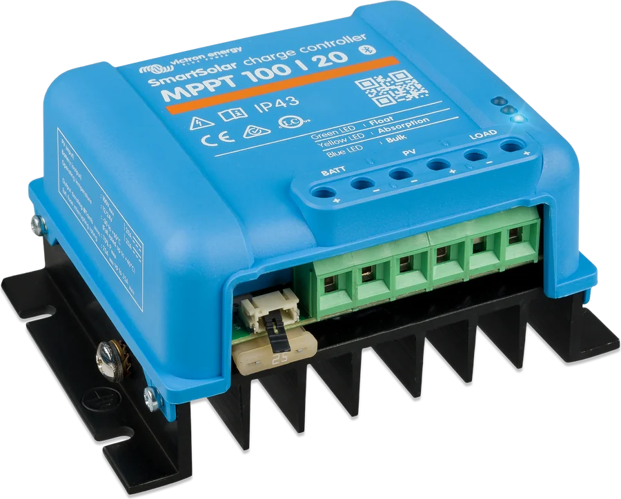
No — the MultiPlus-II has no PV input. Panels are connected through an MPPT solar charge controller to the battery (the most common solution in vehicles and off-grid systems) or through a grid-tie inverter on the AC output. In the latter case, the “Factor 1.0” rule described in Victron documentation applies.
How does the MultiPlus-II differ from the older MultiPlus?
It has all the functions of the predecessor, plus the option of an external current sensor (PowerControl and PowerAssist with current transformer: 3 kVA models up to 50 A, 5 kVA up to 100 A), built-in anti-islanding protection and grid-parallel certificates for many countries, which are required in ESS systems.
How many units can I connect together?
Up to 6 identical models in parallel. Three identical models form a three-phase system, and up to six such sets can be connected. The 8, 10 and 15 kVA models can only be paralleled with an external AC switch.
Does the MultiPlus-II have grid-parallel certificates for Poland?
The manufacturer’s website includes PTPiREE certificates and compliance with EU Regulation 2016/631 for Poland. They cover selected models and configurations, so before notifying the installation to the grid operator, check the current certificate for your model.
When does AC-out-2 work?
Only when AC input power is present. After mains failure, the loads on this output are disconnected immediately, and when power returns they come back after a delay of about 2 minutes — the time needed for the generator to stabilise. AC-out-1 always operates.
Is a battery temperature sensor included?
Yes, except on 48 V models — there it is ordered separately. The sensor is mounted on the negative battery terminal and reduces the charge voltage when the battery warms up. The Vsense wires work separately; they measure the voltage directly at the battery and compensate for up to 1 V drop per pole.
What does the ground relay do?
In inverter mode it connects the output neutral conductor to the enclosure, and when external power appears it opens before the input relay closes — this ensures the residual-current device on the output works correctly. The internal mains transformer eliminates the DC component, so a type A RCD is sufficient. By default, the relay is enabled.
Do I need to change any settings after purchase?
With a gel or AGM battery, usually not — those are the factory settings. With any other battery, especially lithium, set the battery type, absorption and float voltages, and charge current before the first charge. You do this via the MK3-USB interface (VictronConnect or VEConfigure) or remotely through the GX device.
Devices it works with most often

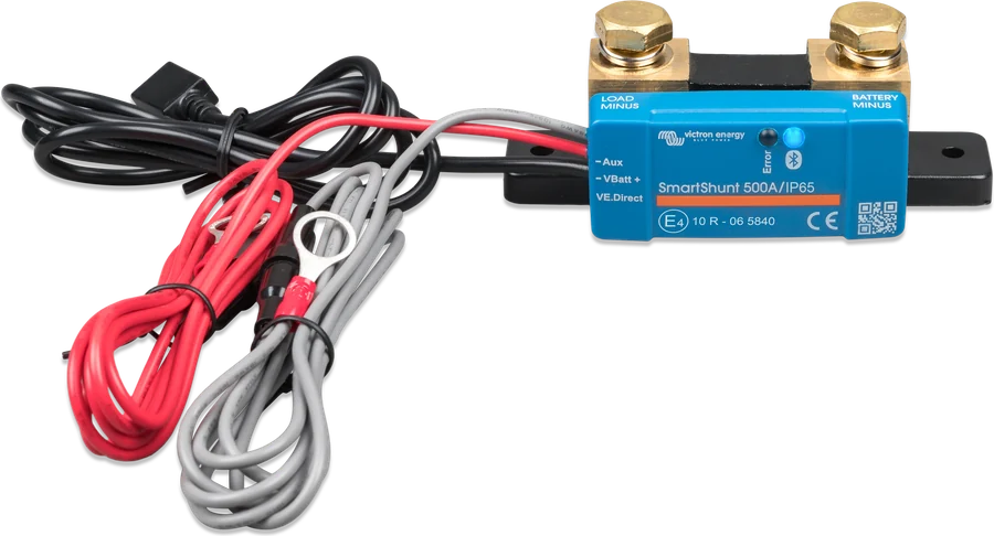
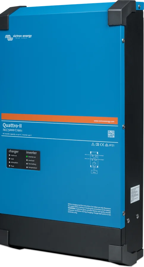
Manufacturer documentation
- MultiPlus-II 230 V datasheetPDF · EN
- MultiPlus-II manualPDF · EN
- MultiPlus-II 4k, 4k5, 6k5, 10k datasheet (new series)PDF · EN
- MultiPlus-II 4k, 4k5, 6k5, 10k 230 V manualPDF · EN
- ESS — design and installationPDF · EN
- Manufacturer’s product page (certificates, drawings)victronenergy.com
We prepared this description independently based on the manufacturer’s documentation. If there are any discrepancies, the current Victron Energy documentation is binding. You can report an error here.
Content checked against Victron Energy documentation (datasheets and manuals) — as of 22 September 2026. Report a content error · Revision log