
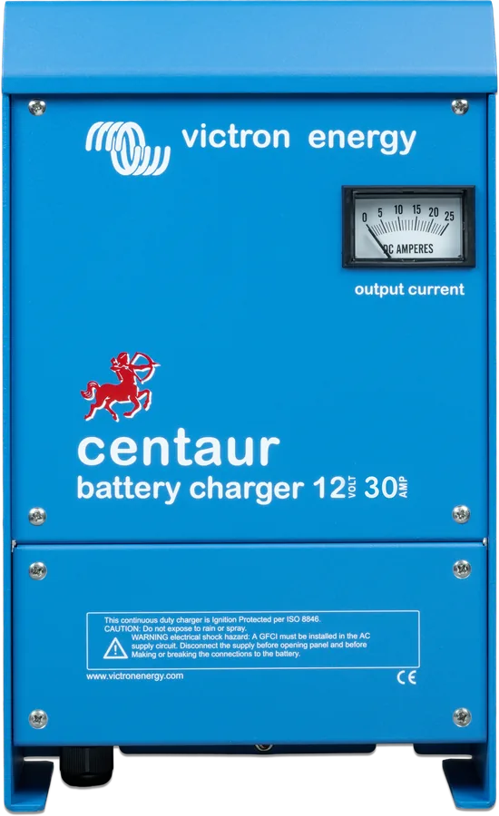
Centaur 12/30 front view — blue housing with output current ammeter and Centaur logo
Centaur Charger
Charger for 12 or 24 V lead-acid batteries with three isolated outputs — charges three banks at the same time, and each output can deliver full current. It works without adjustment from any 90–265 V, 50 or 60 Hz mains, and also from 90–400 V DC. The powder-coated aluminium housing and coated electronics are resistant to heat, moisture and salty air. No Bluetooth — the battery type is selected with a DIP switch.
- 12 V: 20–100 A
- 24 V: 16–60 A
- 3 outputs
- 90–265 V AC / 90–400 V DC
- IP20
Three battery banks from one charger
On a yacht or boat, there are usually separate batteries: starter, house, and for example for the bow thruster. The Centaur charges them all at once from three isolated outputs (common negative). The current is shared between the connected batteries, and when only one battery is connected, it gets the full charger current.
The wide input range (90–265 V AC, 45–65 Hz) lets you use the same charger in marinas with 120 and 230 V mains, from a generator or from an inverter; the charger also accepts 90–400 V DC. The input stage has electronic power factor correction (power factor 1).
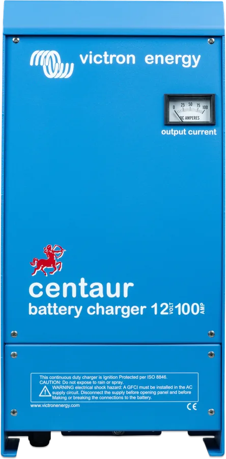
- total output current ammeter on the front panel,
- temperature- and current-controlled fan, output short-circuit and overheating protection,
- ignition protected, galvanically isolated outputs,
- can remain permanently connected to the battery.
The manual describes the Centaur as a charger for lead-acid batteries: open, sealed and gel. There is no LiFePO4 mode or communication with a BMS. For lithium batteries, Skylla, Smart IP43 or the charger in an inverter/charger is a better choice.
Three stages and a DIP switch
The Centaur charges in three stages (IUoU): at full current (bulk), until the current drops to 70% of the rated value — then a 4-hour absorption timer starts — after which it switches to float voltage. An internal sensor compensates the voltage by −2 mV/°C per cell.
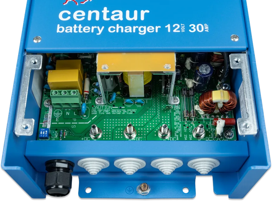
The battery type is selected with the DIP switch in the lower left corner of the PCB (under the lower cover). GEL is selected by default — when changing type, GEL must be switched off.
| Battery type (DIP) | Absorption 12 / 24 V | Float 12 / 24 V |
|---|---|---|
| GEL (factory set) | 14.2 / 28.4 V | 13.5 / 27.0 V |
| AGM | 14.35 / 28.7 V | 13.3 / 26.6 V |
| LA (flooded) | 14.5 / 29.0 V | 13.5 / 27.0 V |
| Other | 14.85 / 29.7 V | 13.7 / 27.4 V |
Voltages according to the manual, at about 10% of rated current; these are indicative values — check the battery manufacturer’s recommendations. The datasheet gives 14.3 / 28.5 V (absorption) and 13.5 / 27.0 V (float) as the standard setting.
Eleven models in three enclosures
| Model | Current | Recommended battery | Current from 120 / 240 V mains | Battery cable (up to 6 m) | Terminals | Enclosure |
|---|---|---|---|---|---|---|
| 12/20 | 20 A | 80–200 Ah | 3.35 / 1.75 A | 10 mm² | M6 | 351 × 214 × 110 mm, 3.8 kg |
| 12/30 | 30 A | 120–300 Ah | 4.35 / 2.30 A | 16 mm² | M6 | 351 × 214 × 110 mm, 3.8 kg |
| 12/40 | 40 A | 160–400 Ah | 6.40 / 3.20 A | 16 mm² | M8 | 437 × 239 × 110 mm, 5 kg |
| 12/50 | 50 A | 200–500 Ah | 8.00 / 4.00 A | 25 mm² | M8 | 437 × 239 × 110 mm, 5 kg |
| 12/60 | 60 A | 240–600 Ah | 9.55 / 4.75 A | 25 mm² | M8 | 437 × 239 × 110 mm, 5 kg |
| 12/80 | 80 A | 320–800 Ah | 12.0 / 6.00 A | 35 mm² | M8 | 514 × 252 × 123 mm, 12 kg |
| 12/100 | 100 A | 400–1000 Ah | 15.0 / 8.00 A | 35 mm² | M8 | 514 × 252 × 123 mm, 12 kg |
| 24/16 | 16 A | 45–150 Ah | 5.55 / 2.50 A | 10 mm² | M6 | 351 × 214 × 110 mm, 3.8 kg |
| 24/30 | 30 A | 120–300 Ah | 9.00 / 4.55 A | 16 mm² | M8 | 437 × 239 × 110 mm, 5 kg |
| 24/40 | 40 A | 160–400 Ah | 10.0 / 6.00 A | 16 mm² | M8 | 514 × 252 × 123 mm, 12 kg |
| 24/60 | 60 A | 240–600 Ah | 15.0 / 9.00 A | 25 mm² | M8 | 514 × 252 × 123 mm, 12 kg |
Full current up to 40 °C ambient; at 50 °C about 80%, at 60 °C about 60%. Input current at a different voltage: current at 120 V × (120 / U) — for example, 12/20 at 110 V: 3.35 × 120/110 ≈ 3.65 A. Common: 90–265 V AC (45–65 Hz) or 90–400 V DC, power factor 1, AC terminal 4 mm², IP20, −20…+60 °C, humidity up to 95% non-condensing. The housings and terminals of the 24 V models are assigned according to the table layout in the datasheet. Cables longer than 6 m are not recommended.
Three battery banks on a yacht
Mains supply in port, from a generator or inverter; three +DC outputs to three batteries, common negative. Simplified diagram.
- Supply voltage90–265 V AC or 90–400 V DC; double-pole switch and PE.
- OutputsThree +DC outputs with fuses, one common −DC.
- Fewer batteriesAny output — each delivers full current.
- DIPBattery type before first switch-on.
Step-by-step installation
Class I device — requires a PE protective conductor. In a fixed installation: a double-pole switch (contact gap at least 3 mm) and an RCD in the supply circuit. Disconnect mains and batteries before working.
- BracketScrew the upper wall bracket in horizontally with three screws.
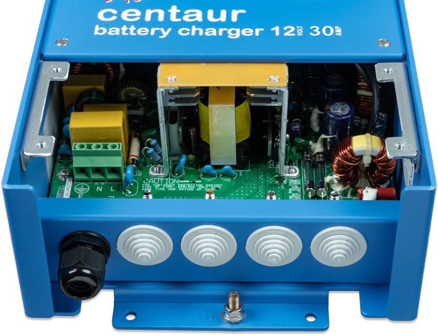
- CoverRemove the lower cover (four screws), hang the charger on the bracket, mark the lower holes and fasten it with M6 screws.
- AC3-core 2.5–4 mm² cable (stranded) to the E, N, L terminal block — cross-section to suit the input current on the nameplate.
- DCCut the cable gland blanks to the cable diameter, connect the battery leads to +DC and common −DC (M6 or M8 lugs), with a fuse sized for the charger.
- Battery typeSet the DIP switch (GEL is factory set).
- Start-upFit the cover, switch on the supply and check that the green “ON” LED lights up (visible through the lower left ventilation openings).
Install vertically if possible (wall-mounted; floor mounting is also possible), in a dry, well-ventilated place, with free space around the ventilation openings. Too high an ambient temperature reduces current, shortens life or switches the charger off. Supply cables must be rated for at least 75 °C.
Troubleshooting
The charger does not work
Measure the mains voltage. If the mains supply is correct, the input or output fuses may be blown — return the unit to the dealer (there are no user-serviceable parts inside).
The battery does not charge fully
Check the battery connections and the DIP setting. The battery may be too large for the charger — compare it with the recommended capacity.
The battery is overcharged
Wrong battery type on the DIP switch, a damaged cell (replace the battery), or a battery that is too small — consult the battery supplier.
Centaur FAQ
Can one output deliver the full current?
Yes. The current is shared between the connected batteries, but each output can deliver the full rated current if only one battery is connected.
Will the Centaur charge a LiFePO4 battery?
The manual covers only lead-acid batteries (open, sealed, gel) and there is no lithium mode or BMS control. For LiFePO4, choose a charger with a lithium mode, such as Skylla or Smart IP43.
Can I power it in port from 120 V mains?
Yes — it accepts 90–265 V AC at 45–65 Hz with no settings. At 120 V it draws more current from the mains (for example, 12/100: 15 A instead of 8 A at 240 V).
Does it have Bluetooth or a Cerbo GX port?
No. The documentation does not provide any communication — there is an ammeter on the front and an LED on the circuit board. Chargers with Bluetooth include Blue Smart IP67, Smart IP43 and Skylla.
What cable for the battery?
Up to 6 m: 10 mm² (12/20, 24/16), 16 mm² (12/30, 12/40, 24/30, 24/40), 25 mm² (12/50, 12/60, 24/60), 35 mm² (12/80, 12/100). Longer cables are not recommended.
Manufacturer documentation
Content checked against Victron Energy documentation (datasheets and manuals) — status as of 23 September 2026. Report an error in the content · Correction log