
01Which program
| Software | When |
|---|---|
| VE.Bus Quick Configure | up to 3 units — in parallel or one per phase |
| VE.Bus System Configurator | 4 units and more, and non-standard systems (e.g. 1 phase in, 3 phases out) |
| VictronConnect | creates systems of up to 3 units and changes the settings of existing systems of 12–15 units; when creating a system, it removes assistants; requires a password |
| VEConfigure 3 | settings for each unit (charging, inverter, assistants) — launched from Quick Configure or System Configurator by right-clicking the unit |
Quick Configure and System Configurator are included in the VE Configuration tools package together with VEConfigure and work only on Windows, with the MK3-USB interface. Victron’s recommended training sequence is: firmware update (VictronConnect) → system setup (Quick Configure or System Configurator) → final settings (VEConfigure). Victron does not support untrained installers working on such systems and advises starting with simpler setups.
02Which units can be connected
- The same type and the same firmware — the same power rating, battery voltage and feature set. The type is defined by the first 4 digits of the firmware number. Update all units to the latest version before setting up the system.
- Compatibility ID from the sticker, for example
2623_B: the digits must be identical throughout the system, and units on one phase must have the same letter. If there is no sticker, use the first 4 digits of the firmware and letter “A”. A mismatch ends with VE.Bus error 25. - The same number of units on each phase (3+3+3 yes, 2+3+3 no). An asymmetrical system works only without monitoring or with a Digital Multi Control panel — it is not supported with GX, a VE.Bus Smart dongle or VRM.
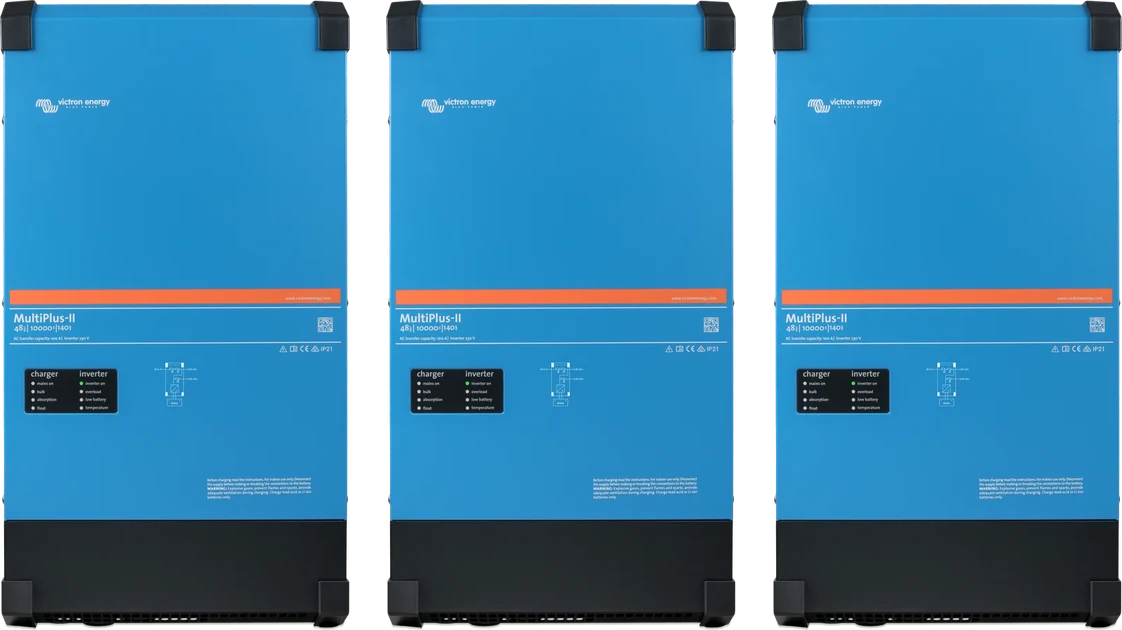
- MultiPlus-II 8k, 10k and 15k in parallel — only with an external AC switch. First-generation EasySolar cannot be connected in systems; EasySolar-II can. Multi RS and Inverter RS have VE.Can, not VE.Bus — separate rules apply to them.
- In one system there is only one Digital Multi Control panel and one GX device.
| Maximum size | Quattro 15 kVA | Models up to 10 kVA |
|---|---|---|
| 3-phase system | 4 per phase, 12 in total — 180 kVA | 5 per phase, 15 in total (for example Quattro 10 kVA — 150 kVA) |
| 1-phase system | 5 units — 75 kVA | 6 Quattro 10 kVA units — 60 kVA |
The figures for the 1-phase system are given verbatim from the Victron manual. The same manual says one sentence earlier that the limit is “the same as per phase” — for a large system, confirm it with your distributor.
03Wiring
- One common DC busbar for all units and all batteries. Splitting the batteries onto separate busbars for some units does not work.
- Phase symmetry: DC and AC cables to each unit must be the same length, type and cross-section, preferably via busbars. Unequal DC cables cause different currents — the unit with the lower voltage will report overload first. You can check this with clamp meters at full load.
- Fuses: each unit separately, the same fuse type — on the DC and AC side. It is worth considering mechanically linked AC fuses.
- Do not oversize the AC cables. Their resistance helps distribute current evenly; cables that are too thick or too short disturb current sharing, PowerAssist operation and charging.
- Star (Y) only with a common neutral conductor — delta is not supported. If the phase order is wrong, the system will not accept the mains and will stay in inverter mode; GX will report a phase sequence alarm.
- VE.Bus cables: factory RJ45 cat. 5 or better, units connected in series (any order), no terminators. Connect the GX at the beginning or end of the chain; do not loop back free sockets. Do not route communication cables alongside power cables (a safe separation is usually about 20 cm).
- Connect the voltage sense wire to the L1 master. The temperature sensor can be in any unit (with several, the highest temperature counts).
- Before connecting the communication cables, connect the negative terminals of the batteries of all units. When removing a unit from the system, disconnect the communication cables first.
04Step-by-step programming (Quick Configure)
- Preparation: up-to-date firmware in all units, VE.Bus cables connected, MK3-USB connected, GX device disconnected (in a MultiPlus-II GX the built-in GX is disconnected internally). If the system is to have a Digital Multi Control panel, it must be connected. In a 3-phase system, connect the AC output neutral conductors. All units must be connected to the battery.
- Start Quick Configure and choose a task: Setup a VE.Bus system (new system), Change settings of an existing VE.Bus system or Reset a Multi to Stand-alone mode (restore the unit to stand-alone operation).
- Choose the configuration from the list. If it is not there, you need System Configurator. Show picture displays the wiring diagram.
- Select the interface COM port.
- Switch off all units (including the panel), then switch them on one by one, following the on-screen instructions. A recognised and programmed unit changes from grey to blue.
- Right-click the unit: Flash LEDs (LED flashing — you can check which unit is which and whether the AC wiring is correct) or launch VEConfigure.
- Done finishes programming. Then set the parameters in VEConfigure.
VE.Bus System Configurator works in the same way, but allows more units and non-standard setups. Victron does not publish a separate online manual — the screen descriptions are in the built-in help in the program and in Victron Professional training. There you also disable the Switch as group function when the generator is connected to only one of the units (not available in ESS).
05Where to enter which settings
| Unit | Settings |
|---|---|
| L1 master | absorption and float voltages, maximum charge current (multiplied by the number of units: 9 units × 50 A = 450 A), system frequency, ignore AC input in Virtual Switch |
| Master of each phase | inverter output voltage, input current limit, UPS, PowerAssist, wide input frequency range, Weak AC |
| Each unit | grid code and AC voltage thresholds, low battery voltage shutdown thresholds; ESS, PV Inverter Support and BMS assistants — in every unit |
- After a change in the first unit, VEConfigure offers to send it to all of them.
- Input current limit: in VEConfigure, the value on the master is multiplied by the number of units in the phase (10 A with 2 units = 20 A). In GX and on the DMC panel you enter one value — that is the total limit per phase.
- AES does not work in parallel or multi-phase systems. With DVCC and a battery on CAN, the battery overrides the charging settings.
06Unit replacement and settings backup
- Backup on GX (Venus OS v3.60+): Settings → Devices → [Multi/Quattro] → Advanced → Backup & Restore. Save the firmware version in the backup name — only a backup matching the unit’s firmware can be restored. Restoring with assistants restarts the system, and password-protected settings (for example the grid code) require the password.
- Via VRM: after commissioning, always archive the
.rvscfile from Remote VEConfigure. After replacing a faulty unit, load the same firmware as the other units onto the new one and send the archived file — VRM will accept one changed serial number (Venus OS v2.62+). - Firmware updates erase settings — afterwards, you must reprogramme the whole system (VE.Bus update).
- System restart: switch off all units one by one, then switch them all back on. An alarm in one unit of a three-phase system (low voltage, overload, temperature, ripple) shuts all of them down.
07Typical errors
| VE.Bus error | Meaning |
|---|---|
| 1 | unit switched off because another phase switched off — look for the cause in the phase that does not show error 1 |
| 3 | not all units were found, or there are too many — cables, blown DC fuse, two systems connected together |
| 17 | missing phase master — only on slave units, in systems with several units per phase |
| 19 | slave unit without AC input |
| 25 | incompatible configuration — different firmware or incompatible compatibility ID |
All codes: VE.Bus error codes. You can see the communication error counter in VRM by adding /diagnostics to the installation address — after start-up and restart it should be 0, and more than 10 in a new system means there is a wiring problem.
Devices this applies to
 MultiPlus-IIInverter/charger with UPS function: pure 230 V sine wave, PowerAssist supports a weak shore connection.
 QuattroInverter/charger 3–15 kVA with two AC inputs — mains and generator without an external changeover switch.
 Quattro-IIInverter/charger with two AC inputs — mains and generator without an external changeover switch.
 MK3-USB interfaceCable between the VE.Bus port and a computer — without it you cannot change settings or update the MultiPlus.
Related
- VEConfigure — settings for each unit.
- VE.Bus Assistants — which ones to load into all units.
- Quattro and MultiPlus-II — device datasheets.
Sources
- Parallel, split- and three-phase VE.Bus systems (status 03/2026)victronenergy.com · EN
- VE.Bus Quick Configure — procedurevictronenergy.com · PDF · EN
- VE.Bus Error Codesvictronenergy.com · EN
- Troubleshooting VE.Bus network interferencevictronenergy.com · EN
- Cerbo GX manual — chapter 11 (phase current limit, Backup & Restore)victronenergy.com · EN
- Victron training “Multi and Quattro — parallel and 3 phase” (2020)victronenergy.com · PDF · EN