
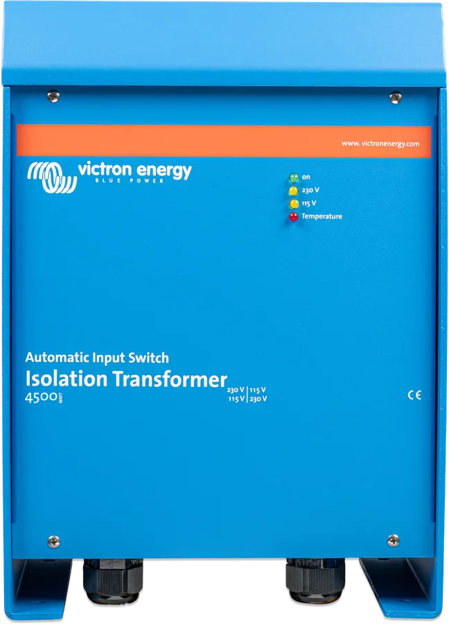
Isolation Transformer 4500 W Auto 115/230 V front view — blue enclosure with on, 115 V, 230 V and temperature LEDs
Isolation Transformer 2500, 4500 and 8000 W
An isolation transformer breaks the electrical connection between the shore supply and the boat. Shore earth does not reach the boat’s metal parts, so no galvanic current flows to destroy anodes, the shaft and the propeller. At the same time, the RCD and overcurrent protection on the boat side still work. Toroidal, with soft start, it operates on 115 and 230 V systems.
- 2500 / 4500 / 8000 W
- 115 or 230 V, 50/60 Hz
- soft start
- 1:1.05 ratio
- IP21
Safe shore connection without corrosion
Shore power is mains supply: the circuit breaker and RCD work thanks to the protective conductor connected to earth. However, connecting this conductor to the boat’s metal parts causes galvanic corrosion. Disconnecting it is dangerous in turn — in the event of a short circuit to a metal part of the boat, neither the RCD nor the fuse will operate.
An isolation transformer solves both problems: the shore supply feeds its primary winding, and the boat is connected to the secondary. On the boat side, the output neutral is connected to the protective conductor and all metal parts of the boat — this means the RCD on the transformer output will trip in the event of a short circuit.
- according to Victron, replaces a galvanic isolator and polarity alarm,
- soft start — does not trip the shore protection with inrush current,
- toroidal transformer (quiet, lighter), fan-cooled with temperature control, with overtemperature shutdown,
- also converts 230 V to 120 V and 115 V to 240 V — but does not change the 50/60 Hz frequency.
Where corrosion from shore power comes from
Galvanic corrosion occurs when two different metals that are electrically connected are both immersed in a conductive liquid — seawater, and to a lesser extent freshwater. The more active metal corrodes, while the nobler one is protected. The rate depends, among other things, on the surface area ratio, water conductivity, temperature and type of metals.
Victron stresses that this is not only a problem for steel or aluminium hulls: it affects any boat whose metal part — for example the shaft and propeller — has contact with water. Once connected to shore power, the protective conductor connects these metals to the port earth and to other boats; anodes wear out very quickly, and then corrosion of the shaft, propeller and other parts begins.
Shore PE connected to the boat
The RCD works, but galvanic current flows — corrosion of the anodes, shaft and propeller.
corrosionWithout PE conductor
No corrosion from shore power, but in the event of a short circuit to metal on the boat, neither the RCD nor the fuse will operate.
risk of electric shockIsolation transformer
No connection to shore power, and the RCD on the transformer output works thanks to the N–PE bridge on the boat side.
safe and corrosion-free2500 W, 4500 W, 4500 W Auto, 8000 W
| 2500 W | 4500 W | 4500 W Auto | 8000 W | |
|---|---|---|---|---|
| Number | ITR040252042 | ITR040452042 | ITR050452042 | ITR000802002 |
| Input | 115 or 230 V (jumpers) | 115 or 230 V (jumpers) | 115 or 230 V — automatic selection | 230 V |
| Output | 120 or 240 V | 120 or 240 V | 120 or 240 V | 240 V |
| Output current | 22 A (115 V) / 11 A (230 V) | 38 / 19 A | 38 / 19 A | 35 A |
| Min. cable | 4 mm² (115 V) / 2.5 mm² (230 V) | 6 / 4 mm² | 6 / 4 mm² | 6 mm² |
| Dimensions (H × W × D) | 445.6 × 214.5 × 135 mm | 362 × 258 × 221 mm | 362 × 258 × 221 mm | 362 × 258 × 243 mm |
| Weight | 12.1 kg | 22.2 kg | 21.8 kg | 28.17 kg |
Common: 50/60 Hz, soft start, toroidal 1:1.05, aluminium IP21 enclosure (indoor use only, no water, mist or dust; no explosion protection), −20…+40 °C, humidity up to 95% non-condensing, EN 60076. The datasheet gives output “115 or 230 V” and an input switch; the manuals give 120/240 V output (a 1:1.05 ratio effect) and require protective devices in the connection cables. Victron also publishes datasheets for the older 2000, 3600, 3600 Auto and 7000 W series (e.g. 3600 W: 32/16 A; 7000 W: 32 A) — with different weights in the two versions of the datasheets.
88–130 V: 115 V mode (yellow “115V” LED); 185–250 V: 230 V mode (yellow “230V” LED); below 88 V and between 130 and 185 V the input and output are switched off. Green “on” LED — operating; red “Temperature” LED — lights when the fan is running.
Quayside → transformer → RCD → boat installation
According to the example in the manual: shore supply through a switch and cable, transformer, RCD on the output and the boat’s AC loads. Schematic only — the connection is to be made by an electrician in accordance with local regulations.
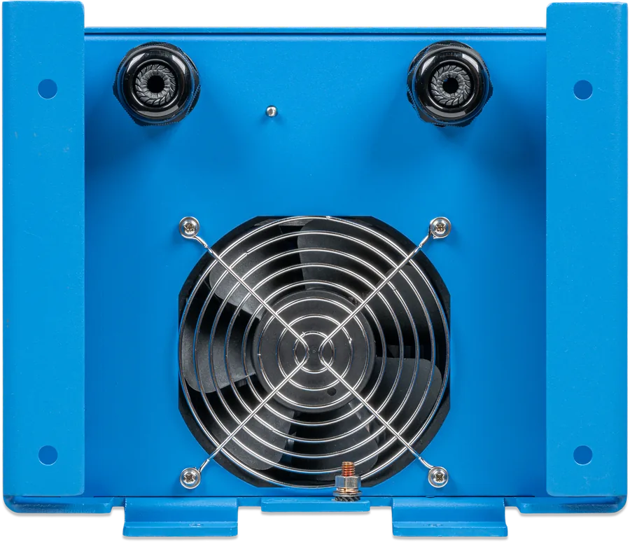
- InputShore cable through the left cable gland: PE, N, L to the INPUT terminal block.
- OutputBoat installation through the right cable gland: PE, N, L to the OUTPUT terminal block.
- EnclosureM6 screw under the housing for earthing the boat (all metal parts).
- N–PE bridgeGreen-yellow J33–J21 jumper — without it, the RCD on the output will not operate.
- RCDRequired on the transformer output.
Voltage jumpers and N–PE bridge
Input and output voltage are set with the black jumpers (included) on the 6.35 mm connectors above the terminal blocks. Check the configuration before first switch-on.
| Setting | 115 V | 230 V |
|---|---|---|
| Input | J17–J20 i J4–J7 | J4–J20 |
| Output | J29–J32 i J31–J25 | J31–J32 |
- Output N–PE bridge: short green-yellow J33–J21 jumper — necessary for the output RCD to work.
- Connection order: shore cable through the left cable gland, cable to the boat through the right; on both terminal blocks first PE, then N, L last; M6 screw under the housing to the boat ground.
- Installation: at least 10 cm of free space all around, good ventilation, non-flammable surroundings (no fabrics or plastics nearby). Mounting bracket and 7 screws included.
Jumper numbers according to the 2500 W and 4500 W manual. The 8000 W model has only 230 V and different numbers: output N–PE bridge J5–J7, boat on shore power J9–J12; its earthing jumpers are 6 mm², which according to the manual — depending on local regulations — may be too little for fault current. 4500 W Auto does not require input voltage setting.
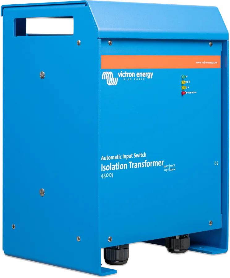
Winter storage and service work
When the boat is ashore (in winter or during work), its protective conductor should be connected directly to the protective conductor of the shore supply. The transformer has a long green-yellow jumper for this (included) between connectors J34A and J34 (on the 8000 W: J9 and J12). After launching, remove it — otherwise the connection to shore earth will return and with it galvanic corrosion.
Class I device. Connection, cable sizes and protection according to local regulations; protective devices must be fitted in the connection cables. Do not open the housing while energised. We describe shock protection details in the guide earthing and RCD.
Frequently asked questions about the isolation transformer
Isolation transformer or galvanic isolator?
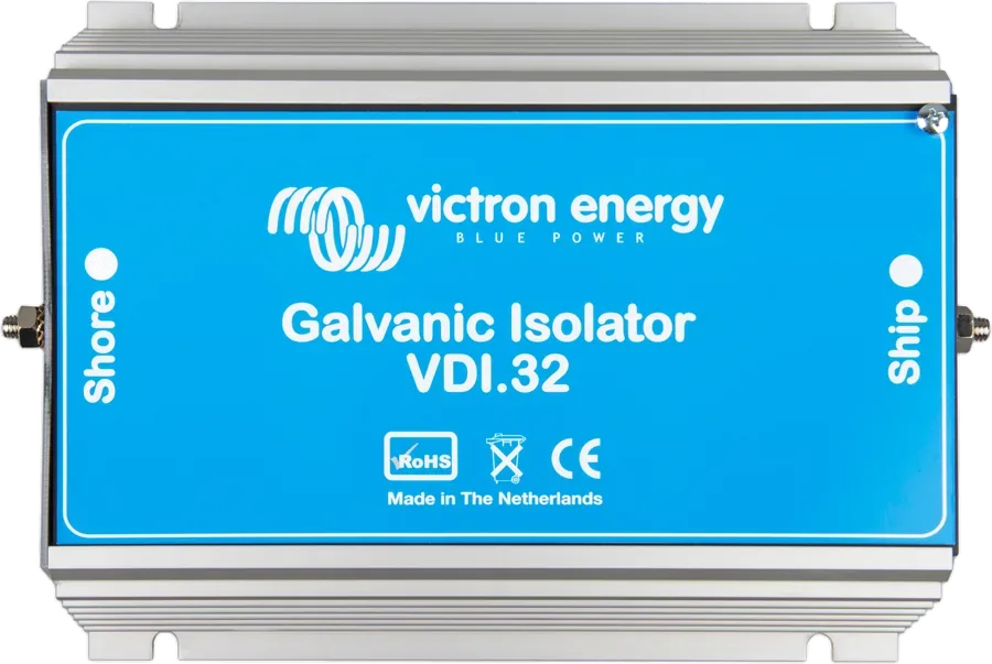
A galvanic isolator (VDI) blocks only the low DC voltages in the protective conductor — it is smaller and lighter. The transformer completely separates the boat from shore power and, according to Victron, replaces the galvanic isolator and polarity alarm. It also has the advantage of raising the voltage by 5% and converting 115/230 V.
Why is the output 240 V, not 230 V?
A 1:1.05 ratio raises the voltage by 5% to compensate for the voltage drop typical in marinas. 230 V becomes 240 V, and 115 V becomes 120 V.
Will it convert 60 Hz to 50 Hz?
No. The transformer works at 50 and 60 Hz, but it does not change frequency — it only changes voltage (for example, 115 V from the marina to 240 V on the boat).
Why does the shore-side protection not trip when it is switched on?
The transformer has a soft start (inrush current limiter). Without it, the large magnetising current at switch-on could trip the shore-side breaker.
Can I install it outdoors?
No. The enclosure is IP21 — indoor use only, with no water, mist, snow, spray or dust; the unit is not explosion-proof.
Manufacturer documentation
- Datasheet Isolation Transformers 2500, 4500, 8000 Wvictronenergy.com · PDF · EN
- Manual Isolation Transformer 2500 W (rev 12, 03/2025)victronenergy.com · EN
- Manual Isolation Transformer 4500 W (rev 00, 01/2026)victronenergy.com · EN
- Manual Isolation Transformer 4500 W Auto (rev 00, 01/2026)victronenergy.com · EN
- Manual Isolation Transformer 8000 W (rev 00, 01/2026)victronenergy.com · EN
Content checked against Victron Energy documentation (datasheets and manuals) — status as of 23 September 2026. Report an error in the content · Correction log