
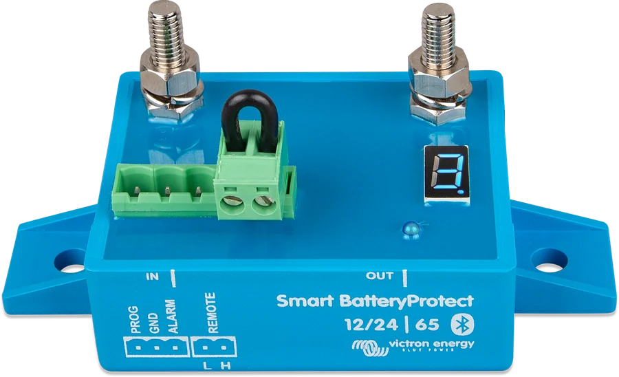
Smart BatteryProtect 12/24 V 65 A — IN and OUT terminals, PROG/GND/ALARM/REMOTE strip and code display
Smart BatteryProtect
An electronic switch in the positive lead of DC loads. It disconnects them before the battery is discharged too deeply or there is not enough energy to start the engine. It protects loads against overvoltage and can be used as the master switch for the whole system. With a lithium battery, it follows BMS commands.
- 65 / 100 / 220 A
- 12/24 V (automatic)
- Bluetooth
- Li-ion mode
- Spark-free (MOSFET)
Delays that do not interfere with starting
- When battery voltage falls below the disconnect threshold, the alarm output switches on after 12 seconds (buzzer, LED, relay), and after 90 seconds the loads are disconnected. If voltage recovers in that time (for example after starting the engine), nothing is disconnected — starting alone will not trigger an alarm.
- The loads are reconnected 30 seconds after voltage rises above the reconnect threshold.
- Above 16.3 V (32.6 V in a 24 V system) the loads are disconnected immediately — overvoltage protection.
- The remote (H/L) input can be used as a master switch for the whole system; when opened, it disconnects immediately.
- Switched by MOSFETs, without a relay — no sparking.
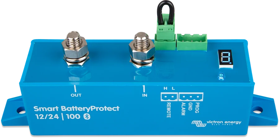
A, B or C
| Mode | When | Behaviour |
|---|---|---|
| A | buzzer or LED (factory default) | Low voltage: continuous alarm after 12 s, disconnect after 90 s. Overvoltage: immediate disconnect and intermittent alarm until the cause is removed. |
| B | relay | Low voltage: relay after 12 s, disconnect after 90 s. Overvoltage (16 V / 32 V): immediate disconnect, alarm output inactive. |
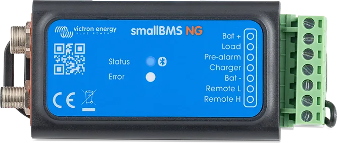
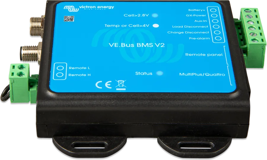
| C | Li-ion with a BMS that has an output to disconnect loads or charging (VE.Bus BMS, smallBMS, Lynx Smart BMS — ATD/ATC contact) | Disconnects immediately when the BMS signal disappears; remains disconnected for at least 30 s. The Smart BatteryProtect undervoltage thresholds and alarm output are then inactive. |
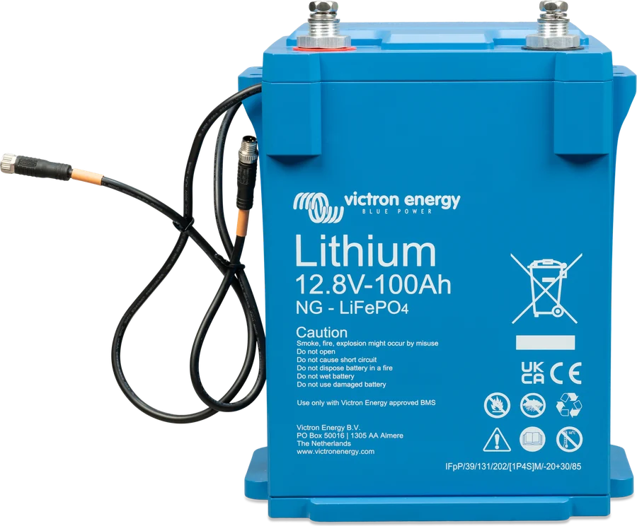
“Drop-in” batteries with built-in BMS, which do not have an output for controlling loads, require mode A or B — mode C is not suitable for them. In Victron’s official diagram for a yacht with Lynx Smart BMS NG, the Smart BatteryProtect 220 operates in Li-ion “C” mode, controlled by the ATD signal.
After disconnection due to low cell voltage in mode C, after three reconnect attempts the Smart BatteryProtect waits until battery voltage exceeds 13.0 V (26.0 V) for at least 30 s — a sign that the battery is being charged.
Two devices can control the loads and the charger separately: when controlling a charger, route the charger positive to IN and OUT to the battery, always following the IN → OUT current direction. Do not use the Smart BatteryProtect for charging from battery to battery.
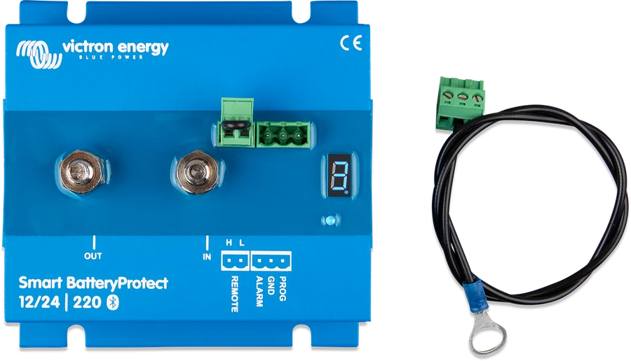
Preset disconnect and reconnect thresholds
| Display | Disconnect 12 / 24 V | Reconnect 12 / 24 V |
|---|---|---|
| 0 (factory default) | 10.5 / 21.0 V | 12.0 / 24.0 V |
| 1 | 10.0 / 20.0 V | 11.5 / 23.0 V |
| 2 | 9.5 / 19.0 V | 11.5 / 23.0 V |
| 3 | 11.25 / 22.5 V | 13.25 / 26.5 V |
| 4 | 11.5 / 23.0 V | 13.8 / 27.6 V |
| 5 | 10.5 / 21.0 V | 12.8 / 25.6 V |
| 6 | 11.5 / 23.0 V | 12.8 / 25.6 V |
| 7 | 11.8 / 23.6 V | 12.8 / 25.6 V |
| 8 | 12.0 / 24.0 V | 13.0 / 26.0 V |
| 9 | 10.0 / 20.0 V | 13.2 / 26.4 V |
In VictronConnect you can also set custom thresholds. Without a phone, it is programmed with a jumper or button between the PROG and GND pins; before this procedure you must remove the loop from the remote on/off terminal. The display scrolls through values 0–9, then the modes (A, b, C), system voltage detection (d), Bluetooth on and off (F, h) and PIN reset (P). System voltage (12 or 24 V) is detected only once, at first start-up.
How to connect the Smart BatteryProtect
The device is wired into the positive lead of the loads: current flows only from IN to OUT. You must not power an inverter through the BatteryProtect — control it via the remote input. Simplified diagram.
- Direction IN → OUTBattery on IN, loads on OUT. Reverse current damages the device.
- Fuse and GNDFuse before the IN input; 1.5 mm² GND lead straight to the negative terminal.
- Program firstSet the mode and thresholds, then connect the OUT terminal.
- Inverter separatelyPowered directly from the battery, controlled by the remote input.
- With a lithium batteryMode C and the ATD signal from the BMS — immediate disconnect.
What to watch out for
Do not connect an inverter or inverter/charger on the DC side through the Smart BatteryProtect — reverse current will damage it, and the input capacitors will trip the short-circuit protection. The inverter is controlled via its remote input, and the Smart BatteryProtect can control that input.
- Direction: current flows only from IN (battery) to OUT (loads). Reverse current from OUT to IN damages the device.
- Close to the battery (max. 50 cm), in a ventilated place — but not above the battery.
- Fuse sized according to local regulations in the lead between the battery and the IN input; cable sized for the load — excessive voltage drop can trigger a short-circuit alarm when a load starts.
- GND lead (1.5 mm², included) directly to the battery negative or vehicle chassis ground, with no other devices in between; 300 mA protection is sufficient.
- Program first, then connect the OUT terminal.
- Alarm output: buzzer, LED or relay matched to the system voltage, connected between the alarm output and the battery positive; load up to 50 mA.
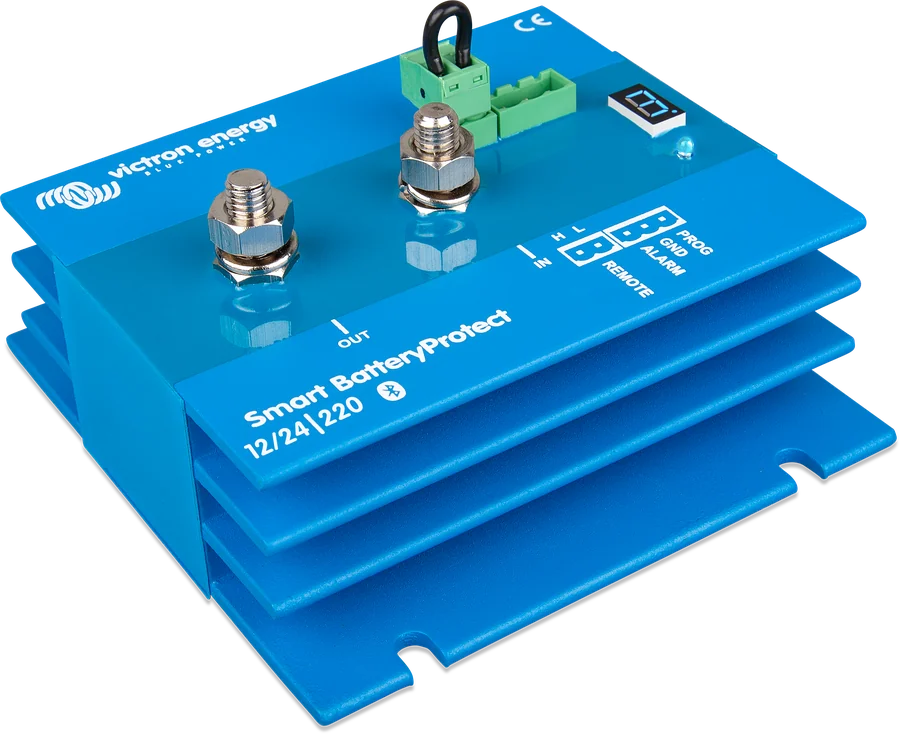
Errors and warnings
| E0 | calibration error |
| E1 | short circuit — after detection it tries to switch on every 5 s, after two attempts it shows E1 |
| E2 / P2 | overtemperature / temperature warning |
| E3 / P3 | undervoltage / low-voltage warning |
| E4 | overvoltage |
| E5 | configuration error |
| E6 | reference voltage error |
| E7 | BMS lockout |
| E8 | reverse current |
After 5 minutes the code disappears from the display (power saving); it remains visible in VictronConnect, also without pairing (Instant Readout). Decimal point: lit — switching-on attempt; flashes every 5 s — output active; every 2 s in Li-ion mode — switching on in progress. Description of each code and what to do: Smart BatteryProtect error codes.
Specifications
| SBP-65 | SBP-100 | SBP-220 | |
|---|---|---|---|
| Continuous current | 65 A | 100 A | 220 A |
| Peak current (30 s) | 250 A | 600 A | 600 A |
| Terminals / torque | M6 / 5 Nm | M8 / 9 Nm | M8 / 9 Nm |
| Weight | 0.2 kg | 0.5 kg | 0.8 kg |
| Dimensions (h × w × d) | 48 × 55 × 106 mm | 61 × 41 × 164 mm | 60 × 123 × 121 mm |
Common: operating voltage 6–35 V; consumption 1.4 mA (Bluetooth on) or 1.2 mA (off), after disconnect 0.9 / 0.7 mA; full load from −40 to +40 °C (60% at 50 °C); electronics IP67 (potted), terminals IP00. For 48 V systems there is a separate Smart BatteryProtect 48 V-100 A (24–70 V, factory disconnect 42 V, reconnect 48 V).
Frequently asked questions about the Smart BatteryProtect
Can I power an inverter through it?
No. Reverse current from the inverter will damage the device, and its input capacitors will trip the short-circuit protection. The inverter is powered directly from the battery, and the Smart BatteryProtect can control its remote input.
Why do the loads not disconnect immediately?
This is intentional: after voltage falls below the threshold, the alarm output switches on after 12 seconds, and the loads are disconnected only after 90 seconds. If voltage recovers sooner (for example after starting the engine), nothing is disconnected. Reconnection happens 30 seconds after voltage rises above the threshold.
Which mode should I choose for a lithium battery?
Mode C — then the device follows the BMS commands (ATD signal) and disconnects the loads immediately when it disappears. “Drop-in” batteries with built-in BMS, which do not have an output for controlling loads, require mode A or B.
Does it also protect against overvoltage?
Yes. Above 16.3 V (32.6 V in a 24 V system) the loads are disconnected immediately.
How do I connect the GND lead?
Using the supplied 1.5 mm² cable directly to the battery negative or vehicle ground, with no other devices in between; 300 mA protection is sufficient. Current direction is always IN → OUT.
Manufacturer documentation
Content checked against Victron Energy documentation (datasheets and manuals) — as of 19 September 2026. Report a content error · Revision log