
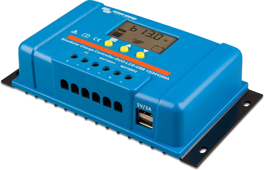
BlueSolar PWM-LCD-USB 12/24 V 20 A at an angle — display, buttons and 5 V / 2 A USB socket
BlueSolar PWM-Light 12/24 V
PWM charge controller for 12 V and 24 V batteries with automatic voltage detection. Three-stage charging (bulk, absorption, float) is not programmable. The load output has low-voltage disconnect, manual control and a lighting timer (one timer).
- 12/24 V auto
- 5 / 10 / 20 / 30 A
- max PV 28 V / 55 V
- IP20
The simplest way to let a panel charge a battery
The PWM controller sits between the panel and the battery and ensures charging takes place in three stages — bulk, absorption and float — so the battery is not overcharged. It detects the system voltage itself: after connecting the battery, it shows “12” or “24” on the display.
It also has a load output: you can connect lighting or another DC load to it, and the controller will disconnect it before the battery is discharged. The built-in timer can switch the light on after sunset and off after a set time.
- four models: 5, 10, 20 and 30 A — for 12 V and 24 V batteries,
- load output with low-voltage disconnect and lighting control,
- self-consumption below 10 mA — the controller draws almost nothing from the battery.
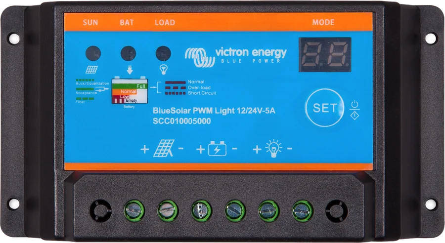

What BlueSolar PWM-Light can do
Three-stage charging
Bulk, absorption and float. The voltages are fixed: 14.2 / 28.4 V in absorption and 13.8 / 27.6 V in float — they cannot be changed.
Automatic 12/24 V detection
The controller recognises the system voltage when the battery is connected — that is why the battery is always connected first. The display then shows “12” or “24”.
Load output
DC load disconnected at 11.2 / 22.4 V. Automatic reconnection at 13.1 / 26.2 V, and manual reconnection with the button — when the voltage exceeds 12.6 / 25.2 V.
Lighting timer
Six output modes: off, timer 1–13 hours after sunset, manual, voltage-controlled only, dusk to dawn and debug mode. Dusk is detected when PV array voltage drops below 4 V.
Protections
Reverse battery polarity (fuse) and PV array, output short circuit, overcurrent and overtemperature. At 130% load the output switches off after 60 s, at 160% after 5 s, and immediately in the event of a short circuit.
Low self-consumption
Below 10 mA, so the controller can remain permanently connected even in a seasonal installation.
LEDs and display
Three LEDs — charging, battery and load — show the charging stage, state of charge and whether the output is on, overloaded or short-circuited.
Indoor installation
IP20 enclosure, convection cooling, terminals up to 5 mm² (AWG10), dimensions 70 × 133 × 33.5 mm. Operation from −20 to +50 °C at full load, common positive earthing.
Four currents, the same 12/24 V voltage
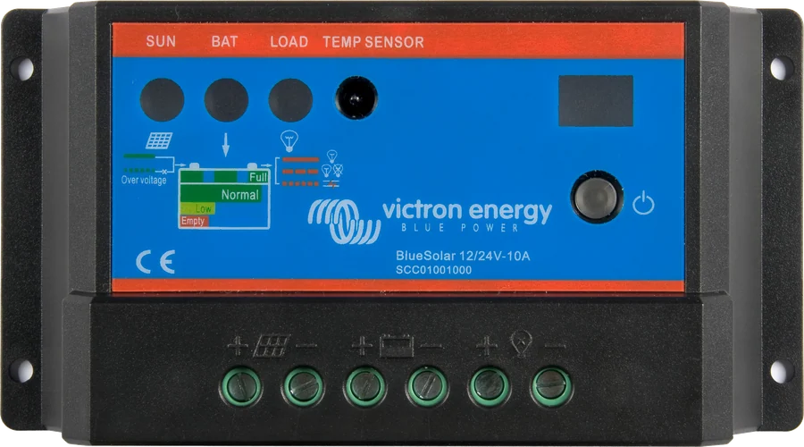
The BlueSolar PWM-Light 12/24 V family has four models. Battery voltage is common: 12/24 V with automatic detection. They differ in rated charge current.
| Model | Battery voltage | Rated charge current |
|---|---|---|
| BlueSolar PWM-Light 12/24-5 | 12/24 V auto | 5 A |
| BlueSolar PWM-Light 12/24-10 | 12/24 V auto | 10 A |
| BlueSolar PWM-Light 12/24-20 | 12/24 V auto | 20 A |
| BlueSolar PWM-Light 12/24-30 | 12/24 V auto | 30 A |
This PWM controller is intended for 36-cell panels with a 12 V battery and 72-cell panels (or 2 × 36 cells in series) with 24 V. Maximum PV voltage is 28 V in a 12 V system and 55 V in a 24 V system. Charging is three-stage and not programmable. If the panels have a different cell layout or a higher voltage, choose SmartSolar MPPT and check the selection guide MPPT selection for panels.
Where BlueSolar PWM sits in the system
Simplified diagram of panels, PWM controller, battery and DC loads. Reference diagram — hover over or tap an element to see its description.
- Battery → controllerAlways connect the battery first. The controller will detect 12 V or 24 V and show it on the display.
- PV panels → PWM36 cells at 12 V, 72 cells or 2 × 36 in series at 24 V. Max. 28 V / 55 V on PV.
- BlueSolar PWMCharges the battery in three stages: bulk, absorption, float. You cannot change the absorption and float voltages.
- FuseOn the battery circuit. Battery reverse-polarity protection (fuse).
- LOAD → DC loadsLoad output with LVD, manual control and one lighting timer.
Voltages, protection, enclosure
| Parameter | 12 V | 24 V |
|---|---|---|
| Absorption voltage | 14.2 V | 28.4 V |
| Float voltage | 13.8 V | 27.6 V |
| Load disconnect (LVD) | 11.2 V | 22.4 V |
| Reconnect — manual | 12.6 V | 25.2 V |
| Reconnect — automatic | 13.1 V | 26.2 V |
| Maximum PV voltage | 28 V | 55 V |
- Self-consumption: < 10 mA.
- Load output: manual control and low-voltage disconnect; protected against overload and short circuit.
- At 130% load — switch-off after 60 s. At 160% load — switch-off after 5 s. In a short circuit — immediate switch-off.
- Earthing: common positive.
- Operating temperature: from −20 to +50 °C at full load. Humidity (non-condensing): max 95%.
- IP20 enclosure. Terminal cross-section: 5 mm² / AWG10. Dimensions (h × w × d): 70 × 133 × 33.5 mm.
- Cooling: natural convection.
- Safety standard: IEC 62109-1. EMC: EN 61000-6-1, EN 61000-6-3, ISO 7637-2.
PWM or MPPT
BlueSolar PWM-Light
36-cell panel for a 12 V battery or 72-cell panel (or two 36-cell panels in series) for 24 V, array voltage up to 28 or 55 V. Simple, low cost and with load output.
5–30 A · 12/24 VSmartSolar MPPT 75–100 V
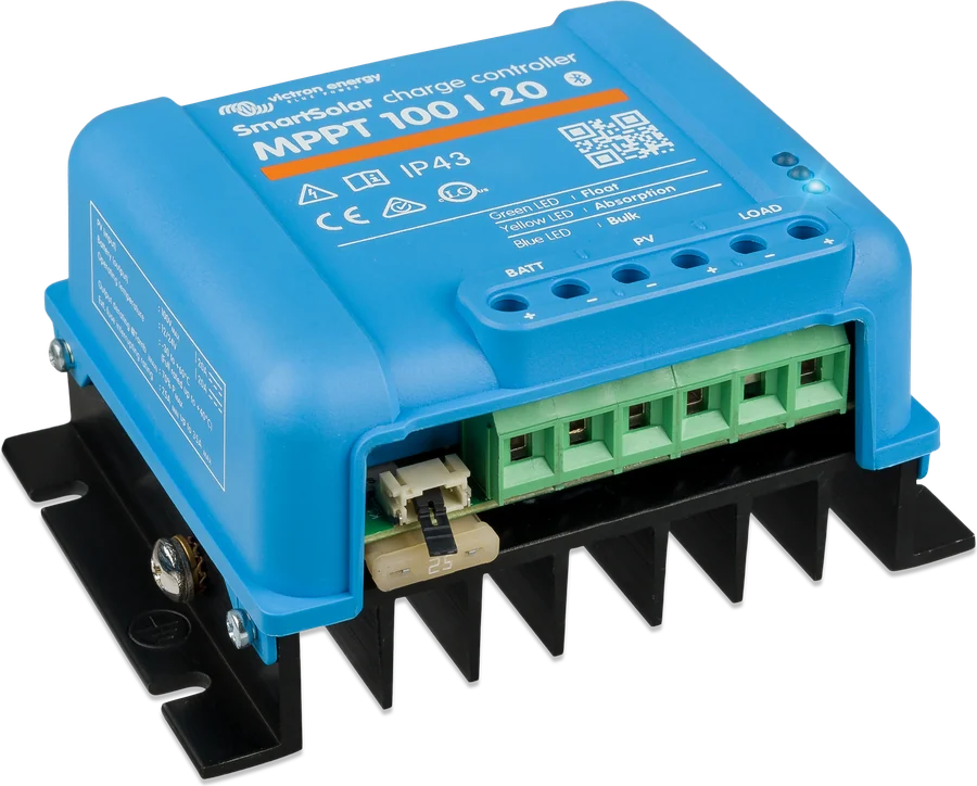
If the panel has a different cell layout or a higher voltage, you need an MPPT controller — it also extracts more energy in cloud and low temperature. SmartSolar MPPT datasheet.
MPPT up to 100 VSmartSolar 100/30 and 100/50
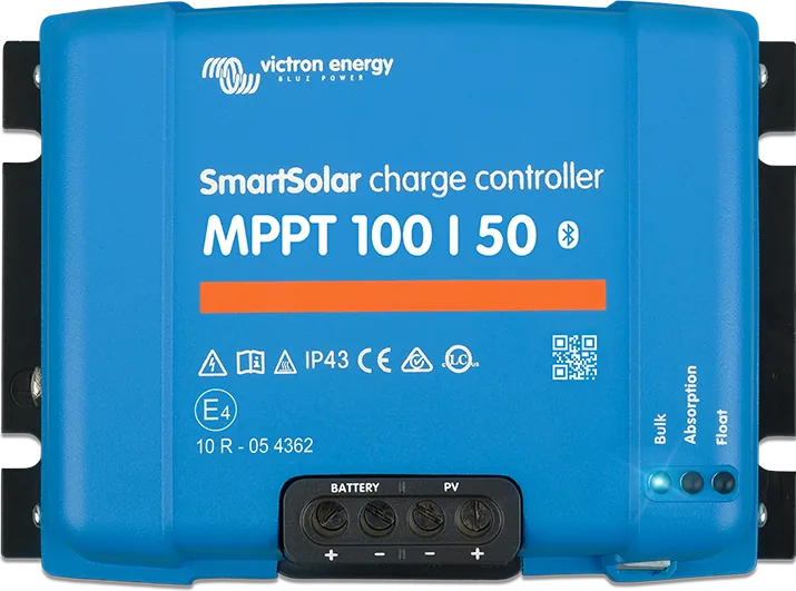
For larger panel arrays and charge currents of 30 or 50 A, with Bluetooth and full charge-voltage configuration. SmartSolar 100/30 and 100/50 datasheet.
30–50 APanel selection for the controller is explained in the guide MPPT selection for panels, and the string size can be calculated with the MPPT calculator.
Connection and location
Always connect the batteries first so the controller can recognise the system voltage. Install indoors only, vertically on a wall. Do not exceed the rated PV and load values.
- After connecting the battery, the display shows “12” (12 V detected) or “24” (24 V detected).
- For a 12 V battery, use a 12 V PV array (36 cells). For a 24 V battery, use a 24 V PV array (72 cells) or 2 × 36 cells in series.
- Protection: battery reverse polarity (fuse), PV array reverse polarity, output short circuit, overcurrent, overtemperature.
- Common positive earthing. Terminals 5 mm² / AWG10. Enclosure rating IP20.
What you can see on the controller
The two-digit display is used to set the load output and shows the detected system voltage, and the three LEDs indicate the charge stage, battery status and output status. Thresholds shown for a 12 V system; in a 24 V system they are twice as high.
Charge LED off
No sun or too little light — the charger is off.
Charge LED flashes rapidly
Bulk stage: the controller charges at the full available current.
Charge LED on continuously
Absorption stage — voltage maintained at 14.2 V (12 V) or 28.4 V (24 V).
Charge LED flashes slowly
Float stage: 13.8 V or 27.6 V. The controller switches to it 2 hours after the absorption voltage is reached.
Battery LED green
Battery fully charged — above 12.7 V in a 12 V system.
Battery LED amber
Normal state of charge: 12.4–12.7 V.
Battery LED red
Low state of charge: 11.2–12.4 V. It is worth reducing the load before the disconnect operates.
Battery LED flashes red
Battery completely discharged — below 11.2 V. At this voltage the load output is disconnected.
Load LED on or off
Shows whether the load output is on or off.
Load LED flashes slowly
Output overload. At 130% of rated current the output switches off after 60 seconds, at 160% after 5 seconds.
Load LED flashes rapidly
Output short circuit — cut-off is immediate.
Output came back on after 30 seconds
This is how the protection works: after an overload or short circuit, the controller tries to switch the output back on after 30 seconds.
Load output and charging
The load output is programmable and has a lighting control mode. The lighting function has only one timer. Day/night options:
| Setting | What it does |
|---|---|
| 0 | charger only. Load output permanently off. |
| 1–13 | delayed light control (timer). The output switches on after sunset (PV array voltage < 4 V) and starts the built-in timer. It switches off after the set time has elapsed or when the low-voltage limit is reached. Setting 1 switches the output on for 1 hour after sunset. |
| H | manual on/off with the button; low-voltage disconnect remains active. |
| C | output controlled only by battery voltage (disconnect and reconnect only by voltage). |
| L | from dusk to dawn, no timer. 10 s switch-on delay when PV array voltage < 4 V. 1 min switch-off delay when PV array voltage > 4 V. |
| d | debug mode: like L, but without the 10 s / 1 min delays. |
After excessive discharge, the output switches on automatically when the battery has charged to 13.1 V / 26.2 V. You can switch the output on manually with the button if the voltage is above 12.6 V / 25.2 V.
Charging is three-stage: bulk – absorption – float; not programmable. The controller switches to the lower float voltage 2 hours after reaching absorption voltage. A new charging cycle starts when battery voltage falls below 13 V.
BlueSolar PWM FAQ
Which panels can I connect?
For a 12 V battery, use 36-cell panels (12 V PV array). For 24 V, use 72-cell panels or 2 × 36 cells in series. Maximum PV voltage is 28 V (12 V system) and 55 V (24 V system). Do not exceed the rated current of the chosen model (5, 10, 20 or 30 A).
In what order should I connect them?
Always connect the batteries first so the controller can detect the system voltage. The display will show “12” or “24”. Install only indoors, vertically on a wall.
Can I change the absorption and float voltages?
No. Charging is three-stage (bulk, absorption, float) and not programmable. Absorption: 14.2 V / 28.4 V. Float: 13.8 V / 27.6 V. Switching to float occurs 2 hours after absorption voltage is reached.
When does the load output return after discharge?
Disconnect occurs at 11.2 V / 22.4 V. Automatic reconnection: 13.1 V / 26.2 V. Manual switch-on with the button: when the voltage exceeds 12.6 V / 25.2 V. In case of overload or short circuit, the output disconnects and tries to restart after 30 s.
When is PWM enough, and when should I choose MPPT?
The PWM in this series is suitable when you have 36-cell panels for 12 V or 72-cell panels (or 2 × 36 cells in series) for 24 V, and you do not exceed 28 V / 55 V on the PV input. With a different cell arrangement or higher panel voltage, you need an MPPT controller — the SmartSolar MPPT datasheet and the guide to choosing an MPPT for panels.
What are the LCD-USB and DUO versions?
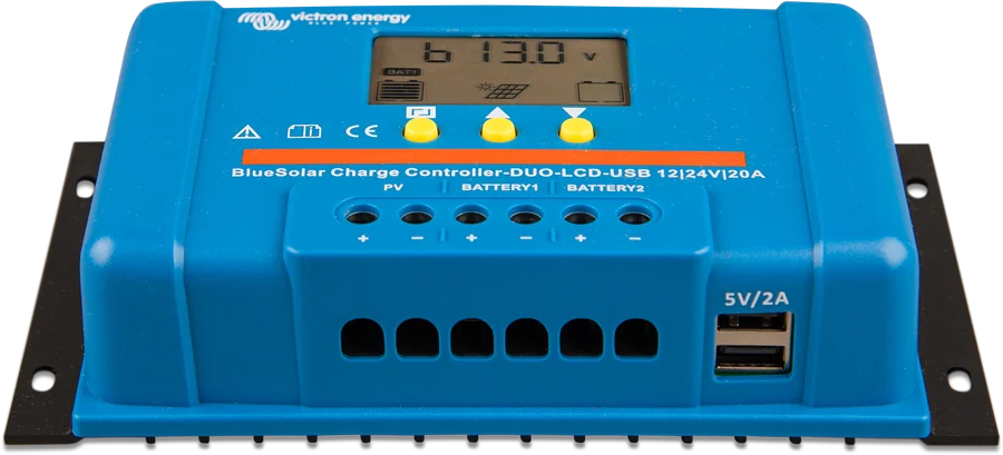
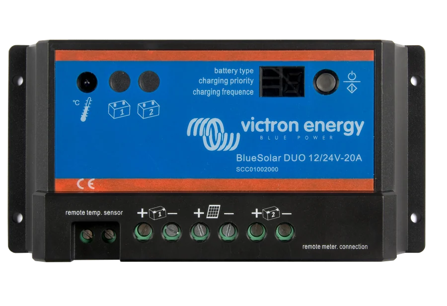
These are other variants of the BlueSolar PWM family. The LCD-USB version has a larger display with battery voltage and a 5 V / 2 A USB socket, while the DUO charges two batteries (BATTERY 1 and BATTERY 2 terminals). The data on this page comes from the datasheet and manual for the PWM-Light version — for other variants, check their own documentation.
What happens if I exceed the load output current?
At 130% of rated current, the output switches off after 60 seconds; at 160%, after 5 seconds; and immediately in the event of a short circuit. After 30 seconds, the controller tries to switch it on again.
How long does absorption last and when does a new cycle start?
The controller switches to float voltage 2 hours after absorption voltage is reached. A new charging cycle starts when battery voltage drops below 13 V.
Will the controller withstand reverse connection?
The manual lists protection against reverse battery polarity (fuse) and reverse PV polarity, as well as output short circuit, overcurrent and overtemperature. Even so, it is worth checking polarity with a meter before connecting.
Where can it be installed?
Only indoors, vertically on a wall — the enclosure is IP20 and is cooled by convection. The full-load operating range is −20 to +50 °C, humidity up to 95% without condensation.
Manufacturer documentation
Content checked against Victron Energy documentation (datasheets and manuals) — as of 19 September 2026. Report a content error · Revision log