
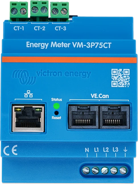
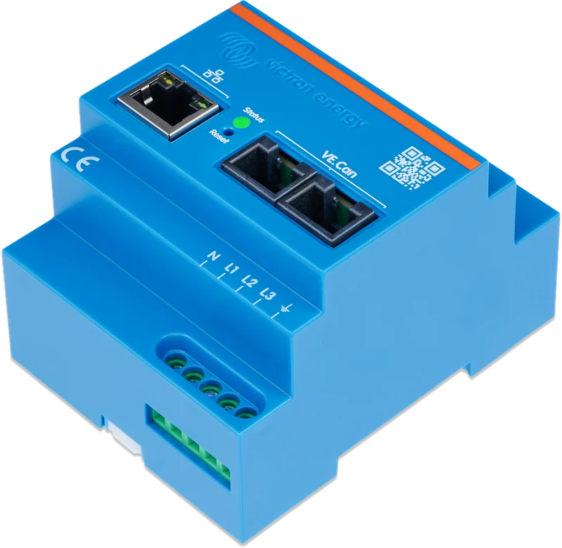
Energy Meter VM-3P75CT — CT-1, CT-2 and CT-3 transformer inputs, Ethernet port, two VE.Can sockets and N, L1, L2, L3 terminals
Energy Meter VM-3P75CT
Victron power and energy meter for single-phase, split-phase and three-phase installations. It most often works as the grid meter in an ESS system — every 100 ms it sends each phase’s power to the GX device, which uses this to control the inverter/charger. It can also measure a PV inverter, generator, AC circuit, EV charger or heat pump.
- 1 phase / split-phase / 3 phase
- 3× 75 A CTs included
- VE.Can
- Ethernet, Modbus UDP
- 100 ms refresh
The ESS system’s eyes at the shore connection
The meter measures power and energy in a single-phase, split-phase or three-phase installation and every 100 milliseconds sends each phase reading to the GX device. On this basis, the GX centre controls the inverter/charger: it draws only as much from the grid as needed and feeds back only the permitted surplus.
Current is measured by split-core 75 A current transformers fitted around the phase conductors — there is no need to cut into the installation. The meter measures voltage using its own terminals. In addition to acting as a grid meter, it can also measure a PV inverter, generator, selected AC circuit, EV charger or heat pump.
- three split-core current transformers included — measurement up to 80 A RMS per phase,
- connection to the GX device via VE.Can or Ethernet (Modbus UDP),
- in addition to power, it reports voltages, phase and neutral currents, power factor and phase sequence.

What the VM-3P75CT can do
Measurement every 100 ms
Each phase’s power is sent to the GX device ten times a second — fast enough for the ESS to keep up with load changes.
Three grid types
Single phase, split-phase or three-phase (factory default). Voltage range 85–265 V phase to neutral and 150–460 V phase to phase, 50 or 60 Hz.
Current transformers without cutting the installation
Three split-core 75 A current transformers with 640 mm cables and a 10 mm opening. They are factory paired with the inputs, so each is fitted on its own phase.
VE.Can and Ethernet
Two VE.Can sockets with terminators included (250 kbit/s profile) and Ethernet with Modbus UDP. On VE.Can, the meter is detected automatically.
Six roles
Grid meter (factory default), PV inverter, generator, AC circuit, EV charger and heat pump. For four of them, you also set whether they operate on the inverter AC input or output side.
A complete picture of the grid
L-N and L-L voltages, phase and neutral currents, power factor, PE voltage and phase sequence — useful when commissioning an installation.
Three energy calculation methods
Vector (factory default), arithmetic or absolute — it is worth setting the same one as used by the energy supplier’s meter.
Low consumption, small enclosure
1.45 W self-consumption, 90 × 71 × 59 mm, IP20 enclosure for indoor distribution-board mounting, operating range −10…+55 °C, overvoltage category III.
VM-3P75CT or VM-3P5A
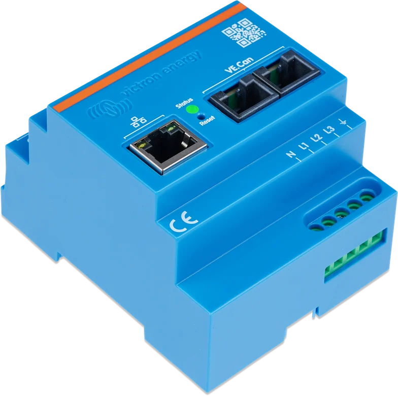
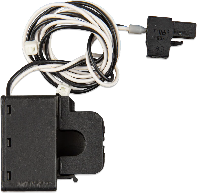
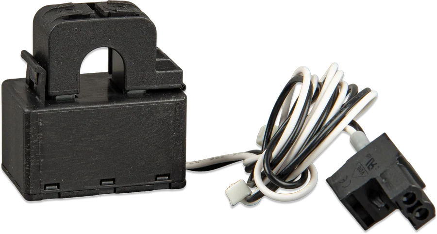
VM-3P75CT
Three 75 A current transformers included, powered from L1–N, consumption 1.45 W. The standard choice for domestic and small commercial ESS.
up to 80 A RMS per phaseVM-3P5A
For industrial 5 A current transformers bought separately — when currents exceed the range of 75 A transformers. Powered from N-L1-L2-L3, consumption 1.85 W.
current transformers sold separately| VM-3P75CT | VM-3P5A | |
|---|---|---|
| Current measurement | 3 × 75 A split-core current transformers included (640 mm cables, 10 mm opening), measurement up to 80 A RMS per phase | industrial 5 A current transformers — bought separately |
| Supply voltage | z L1–N; 1.45 W | z N-L1-L2-L3; 1.85 W |
| Weight | 370 g (with packaging) | 260 g |
Common: 85–265 V L-N and 150–460 V L-L voltage, 50/60 Hz, direct voltage measurement, 1.0–2.5 mm² voltage terminals, VE.Can (2 × RJ45, terminators included) and Ethernet (RJ45, Modbus UDP), IP20 enclosure for indoor use only, −10…+55 °C, overvoltage category III. In addition to power and energy, it reports L-N and L-L voltages, power factor, phase and neutral currents, PE voltage and phase sequence.
How to connect the Energy Meter VM-3P75CT
The meter operates in a 230/400 V distribution board — installation and adjustments must be carried out only by a qualified person, with the power turned off. The current transformers are factory paired with the inputs. Reference diagram.
- Turn off the powerWork in the distribution board only after isolating the supply and only by a qualified person.
- Current transformers on the phasesThe L ← K arrow towards the loads; each current transformer on its own input.
- Voltage terminalsN, L1, L2, L3 via a switch — do not connect two phases to N and L1.
- Connection to GXVE.Can with terminators or Ethernet (Modbus) and enable the device in the GX menu.
- Role in the ESSThe grid meter sends phase power every 100 ms — the GX controls the inverter.
Installation rules
Installation, operation and adjustments must be carried out only by qualified persons, after disconnecting the mains supply, in accordance with national regulations. Do not fit current transformers onto bare conductors.
- Current transformer direction: the “L ← K” arrow points towards the loads. The current transformers are factory paired — fit each one to the correct phase and the correct input, otherwise accuracy will drop. When opening the current transformer, open section A first and do not twist the head.
- Do not connect two phases to the N and L1 terminals — this may damage the meter. Earthing must be done correctly.
- Isolation: a switch or circuit breaker is required as the disconnecting device (not included). With the same cable cross-section as the circuit after the main breaker, no additional switch is needed; in a typical European installation, a 2.5 mm² cable with a 16 A breaker is sufficient. The meter has an internal, non-replaceable fuse.
- Extending the current transformer cables increases measurement noise slightly — twist the cables. A damaged current transformer may only be replaced by a qualified person.
- Dry place, away from fire and flammable materials. Clean with a dry cloth.
VE.Can or Ethernet
- VE.Can — directly to the GX device (Cerbo GX, Ekrano GX); VE.Can port profile 250 kbit/s, terminators at both ends of the network. The meter is detected automatically.
- Ethernet — on the local network (Modbus UDP); in GX go to Settings → Integrations → Modbus Devices → Discovered devices and enable the detected meter (after first start-up the discovered device is disabled by default). A good Ethernet cable; it is best to set the IP address automatically (DHCP).
- The data is available in VictronConnect (directly via Ethernet or remotely via VictronConnect-Remote if the GX device is connected to VRM), on GX and in VRM. For Multi RS Solar it is the only supported meter (VE.Can or Ethernet, no Wi-Fi).
- In most systems it works straight away as a grid meter; according to the manual, a firmware update may be needed (via VRM, VictronConnect-Remote or locally via Ethernet/Wi-Fi).
What to set in VictronConnect
- Role: grid meter (factory default), PV inverter, generator, AC circuit, EV charger, heat pump. For the PV inverter, AC circuit, EV charger and heat pump, also set whether they are on the AC input or output side of the Multi/Quattro.
- Phases: L1 only, three-phase (factory default) or split-phase.
- Energy calculation method: vector (factory default), arithmetic or absolute — confirm with your energy supplier how its meter counts.
- Phase-sequence warning disabled by default. LED pulse: 10 Wh (factory default), 100 Wh, 1 kWh or disabled.
- Current seems too high for the power? Check the power factor — a low value means reactive power (apparent power is then higher than active power).
LED states, reset, codes
A short press of the RESET button restarts the meter, and holding it for about 15 seconds restores factory settings (role: grid meter, three-phase, DHCP address) — after such a reset, you need to configure it again.
Green lit steadily
Normal operation — the meter measures and sends data.
Green flashes once per second
Device identification started from the app is in progress; the state ends after 60 seconds.
Short red flash
Energy pulse. By default every 10 Wh, but you can set 100 Wh, 1 kWh or turn pulses off.
Red lit steadily
Meter error — you can see the number and description in the VictronConnect app or on the GX device display.
Green and red flash rapidly alternately
Bootloader or firmware update. If the state persists, the update failed — reinstall it locally via Ethernet or Wi-Fi, or via the VRM portal.
Error 116 — calibration data lost
The meter is faulty and must be replaced by the seller.
Error 119 — corrupted configuration
The meter stops working. A factory reset is required: hold the RESET button for about 15 seconds, then configure the meter again.
Error 122 — corrupted kWh counters
Reset the energy counters in the app; power measurement continues to work.
Frequently asked questions about the Energy Meter VM-3P75CT
What is the difference between the VM-3P75CT and a direct-measurement meter?
Current is measured by split-core 75 A current transformers clipped around the phase conductors, so you do not need to cut into the installation. The meter measures voltage using its own N, L1, L2, L3 terminals.
How do you orient the current transformers?
The “L ← K” arrow must point towards the loads. The current transformers are factory paired with the inputs, so mount each one on the correct phase and on the correct input — otherwise measurement accuracy drops.
VE.Can or Ethernet?
Both methods work. VE.Can connects directly to the GX device (250 kbit/s profile, terminators at both ends) and the meter is detected automatically. Via Ethernet (Modbus), you need to go in GX to Settings → Integrations → Modbus Devices → Discovered devices and enable the detected device — after first start-up it is disabled by default.
Does the meter work with Multi RS Solar?
Yes — and for Multi RS Solar it is the only supported meter, via VE.Can or Ethernet (no Wi-Fi).
Does it need a separate isolator?
Yes, an isolator or circuit breaker is required as a disconnecting device — it is not included. If the cable cross-section is the same as the circuit after the main breaker, an additional isolator is not needed; in a typical European installation, 2.5 mm² cable with a 16 A breaker is sufficient.
What else can it be used for, if not grid measurement?
For measuring a PV inverter, generator, selected AC circuit, EV charger or heat pump. For these roles, you also need to specify whether the device is on the input or output side of the inverter/charger AC side.
The current seems too high for the power — why?
Check the power factor. A low value means high reactive power: apparent power is then clearly higher than active power, so current increases even though the active power drawn does not change.
Which energy calculation method should you choose?
Vector is set by default; arithmetic and absolute are also available. It is best to set the same method as the supplier’s meter uses — otherwise the readings will diverge.
Can the meter be installed outdoors?
No. The enclosure is IP20 and intended for an indoor distribution board; operating range is −10…+55 °C, overvoltage category III. The location must be dry, away from flammable materials.


Manufacturer documentation
Content checked against Victron Energy documentation (datasheets and manuals) — as of 19 September 2026. Report a content error · Revision log