
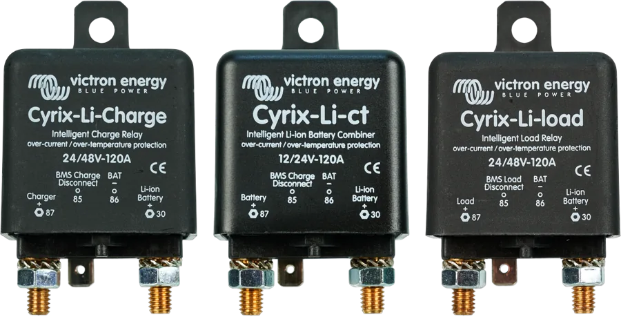
Three Cyrix-Li 120 A combiners side by side — Cyrix-Li-Charge, Cyrix-Li-ct and Cyrix-Li-load
Cyrix-Li-ct, Cyrix-Li-Charge, Cyrix-Li-load
A LiFePO4 battery must disconnect loads before the cells are discharged too deeply, and chargers must disconnect on overcharge, above 50 °C or below 0 °C. The BMS does this, but not every load or charger can be controlled by it directly. Cyrix-Li are power relays that close only when the BMS allows it: Li-ct for the starter battery, Li-Charge for the charger, Li-load for the loads.
- 120 A or 230 A
- 12/24 V or 24/48 V
- control input from BMS
- status LED
- IP54
Second line of protection for a lithium battery
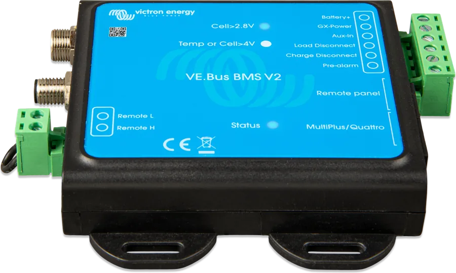
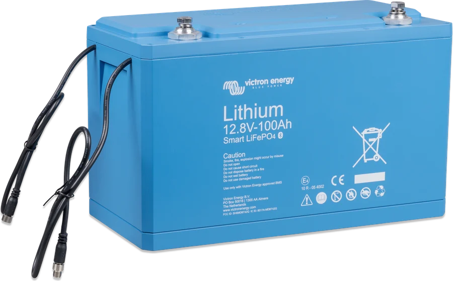
The datasheet describes Victron LiFePO4 battery protection in two stages. The first line is cell balancing built into the battery. The second is disconnecting loads when there is a risk of cell undervoltage, and switching off or limiting charging when cell voltage is too high or the temperature is above 50 °C or below 0 °C. The heart of the second line is the BMS (in Cyrix-Li documentation: VE.Bus BMS).
Some Victron devices (for example an inverter/charger via VE.Bus) are switched off directly by the BMS. A standard charger, alternator or load distribution panel has to be disconnected by a power relay — and that is what Cyrix-Li is for. Each has a control input: when the BMS applies voltage to it (approx. battery voltage), the Cyrix can close; when the input is left open or shorted to minus, the Cyrix opens.
- 120 A and 230 A continuously and as breaking capacity at 12 or 24 V; at 48 V — 40 or 80 A (Li-Charge and Li-load 24/48),
- current draw below 4 mA when open; status LED; IP54,
- 1 m control wire included (230 A models).
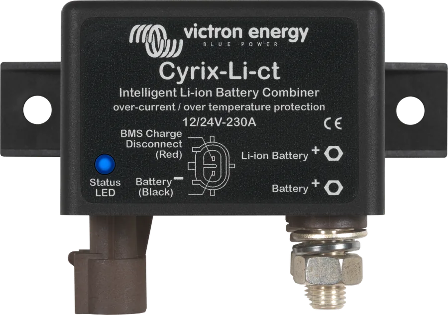
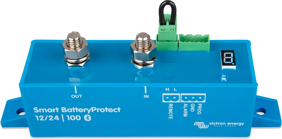
Instead of Cyrix-Li-load, the datasheet specifies BatteryProtect — its advantage is very low current draw.
Li-ct, Li-Charge and Li-load
Cyrix-Li-ct
Works like the Cyrix-ct: it connects the lead-acid starter battery with the LiFePO4 battery when the BMS allows charging and at least 13.4 V (26.8 V) is present on one of the terminals. It disconnects immediately on a BMS signal or below 13.2 V. Starting assist function: a short negative pulse closes the relay for 30 s.
12 V or 24 VCyrix-Li-Charge
Connects the charger with a 3 s delay when the BMS allows charging, the charger terminal has at least 13.0 V (26.0 / 52.0 V), and the battery terminal at least 2 V. Disconnects immediately on a BMS signal (cell overvoltage or temperature). Every hour it disconnects briefly to check whether the charger is still operating.
12/24 V or 24/48 VCyrix-Li-load
Disconnects loads when the BMS reports low cell voltage. When battery voltage returns, it closes again after 30 s. After three attempts it stays open until battery voltage exceeds 13 V (26 / 52 V) for at least 30 s — a sign that the battery is being charged.
12/24 V or 24/48 VThe built-in surge suppressor in the Cyrix-Li-ct limits the voltage spike when it disconnects suddenly due to overcharge or temperature. Note for Cyrix-Li-Charge: with no load or a small load, the Cyrix will not disconnect immediately after the charger is switched off because battery voltage remains above 13.5 V.
Thresholds and parameters
| Cyrix-Li-load | Cyrix-Li-Charge | Cyrix-Li-ct (12 V / 24 V) | |
|---|---|---|---|
| Voltage versions | 12/24 V, 24/48 V | 12/24 V, 24/48 V | 12/24 V |
| Continuous current and breaking capacity at 12/24 V | 120 A (120 A series) or 230 A (230 A series) | ||
| Breaking capacity at 48 V | 40 A / 80 A | 40 A / 80 A | — |
| Turn-on | after BMS signal (described above) | from 13.0 / 26.0 / 52.0 V | 13.4–13.7 V: after 120 s; 13.7–13.9 V: after 30 s; above 13.9 V: after 4 s (24 V: 26.8–27.4 / 27.4–27.8 / above 27.8 V) |
| Disconnect | after BMS signal | after BMS signal | approx. 13.3–13.2 V: after 10 s; below 13.2 V: immediately (24 V: 26.6–26.4 / below 26.4 V) |
| Control input | closes with voltage on the input (approx. battery voltage); opens when the input is left open or shorted to minus | ||
| Current draw (open) | < 4 mA | ||
| Enclosure | IP54; 120 A: 46 × 46 × 80 mm, 0.11 kg; 230 A: 65 × 100 × 50 mm, 0.27 kg | ||
Terminal markings on the 120 A housing: 87 — charger / loads / starter battery side (+), 30 — Li-ion battery (+), 85 — BMS signal (Charge or Load Disconnect), 86 — battery minus. Inconsistencies in the datasheet tables: for Cyrix-Li-Charge the disconnect thresholds are given as “11.5 V < V < 11.0 V: 10 s, V < 10.5 V: immediately”, although the text says disconnection occurs on a BMS signal; the disconnect ranges in the Li-ct column are written the wrong way round (13.3 V < V < 13.2 V).
Cyrix-Li-Charge between charger and battery
According to the diagram in the datasheet: charger via Cyrix-Li-Charge and fuse to the Lithium Smart battery; the Charge Disconnect signal from the BMS controls the Cyrix. Cyrix-Li-load and Li-ct are connected in the same way (respectively: loads and Load Disconnect signal; starter battery with alternator). Illustrative diagram.
- 87Charger plus (Li-load: loads; Li-ct: starter battery).
- 30Through a fuse to the plus of the LiFePO4 battery.
- 85Signal from BMS: Charge Disconnect (Li-Charge, Li-ct) or Load Disconnect (Li-load).
- 86Battery minus.
What the LED indicates
| LED | Meaning |
|---|---|
| on | closed (connected) |
| flash every 10 s | open (disconnected) |
| flash every 2 s | connecting |
| flashing every 2 s | switching off |
| flashing every 0.25 s | alarm: overheating, voltage above 16 V, both batteries below 10 V, or one below 2 V (for 24 V × 2) |
LED description according to the 230 A series datasheet.
Most common questions about Cyrix-Li
Cyrix-Li-ct or a DC-DC charger?
Cyrix-Li-ct connects batteries directly — the lithium battery receives whatever voltage the alternator provides, and the BMS can only disconnect it. With a smart alternator (Euro 5/6) or when controlled charging is needed, a DC-DC charger is better: Orion XS or Orion-Tr Smart.
Why does Cyrix-Li-Charge disconnect briefly every hour?
It checks whether the charger is still working. If, after disconnection, the charger output voltage immediately returns to 13.0 V or more, the Cyrix reconnects after 3 s.
Which BMS does it work with?
The datasheets describe compatibility with VE.Bus BMS (VE.Bus BMS V2 in the diagrams). The Cyrix responds to voltage on the control input, so BMS outputs of the Charge Disconnect and Load Disconnect type are used for control. The smallBMS NG manual also provides for Cyrix-Li-ct and Cyrix-Li-Charge.
Can I use a standard Cyrix-ct with a lithium battery?
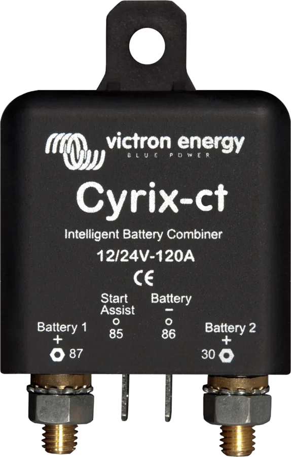
Cyrix-ct has no BMS-controlled input and connects batteries only on the basis of voltage. For Victron lithium batteries, Victron specifies Cyrix-Li-ct — the BMS can disconnect it too.
What is starting assist in the Cyrix-Li-ct?
A short negative pulse on the Start assist input closes the relay for 30 s, allowing the lithium battery to help start the engine when the starter battery is weak. In the diagram in the datasheet, the button must be pressed twice.
Manufacturer documentation
Content checked against Victron Energy documentation (datasheets and manuals) — status as of 23 September 2026. Report an error in the content · Correction log