
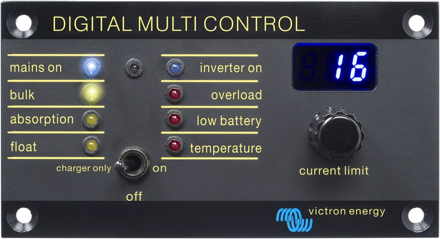
Digital Multi Control panel — mains on, bulk, absorption, float, inverter on, overload, low battery, temperature LEDs, off / charger only / on switch and current limit knob
Digital Multi Control 200/200A
A simple remote control panel for an inverter/charger in a single, parallel, split-phase or three-phase system. On/off/charger-only switch, AC input current limit knob, eight status LEDs and display. No app and no phone.
- VE.Bus (RJ45)
- current limit 0–198 A (generator)
- 8 LEDs + display
- GEN input
Wall-mounted system switch, no phone
Digital Multi Control is a wall-mounted panel — by the campervan entrance, above the navigation table or in the technical cupboard. With one switch you can turn the whole system on, turn it off or leave only the charger on, and with the knob you set the current limit that may be drawn from shore power or a generator.
The panel also mirrors the inverter/charger’s eight LEDs and shows the active AC input or an error code on the display. One network cable to the VE.Bus socket is enough — no app or GX device needed.
- mode switch: on, off, charger only,
- AC input current limit knob — a separate value stored for each input,
- GEN input, which switches the system to the generator current limit when shorted.
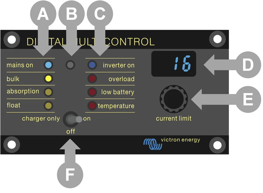

What’s on the panel
Mode switch
On, off or “charger only”. In a system with a GX device and a DMC panel, mode switching works only from the panel.
Current limit knob
The range adapts to the system, and the panel remembers the last value for each AC input. Below 10 A the step is 0.5 A, above that 1 A. You cannot go below the system’s minimum AC current.
Quick switch to inverter
A quick turn of the knob to the left sets 0.0 A — loads stop charging and switch to inverter mode.
Eight LEDs like on the inverter
Charger: mains on, bulk, absorption, float. Inverter: inverter on, overload, low battery, temperature. A light sensor dims them in the dark. The meaning of the combinations is described by the LED decoder.
Display
Shows the set AC input current limit, active source or a VE.Bus error code — without reaching for your phone.
GEN input
Terminals on the back of the panel. When shorted (for example by an auxiliary relay from an external source switch), the panel sends the set generator current limit and shows “GEN”.
One network cable
A standard straight RJ45 UTP cable, 30 cm to 30 m long (sold separately), to a free VE.Bus port. In older systems before VE.Bus — to the main device.
Priority over the rest
The panel has priority over the VE.Bus Smart dongle and the GX device for mode switching and current limiting. The limit works when the inverter setting “overruled by remote” is enabled.
The panel, Bluetooth dongle or GX device
Digital Multi Control
A physical switch and knob on the wall — works without a phone and without mains power. Best where other people also use the system.
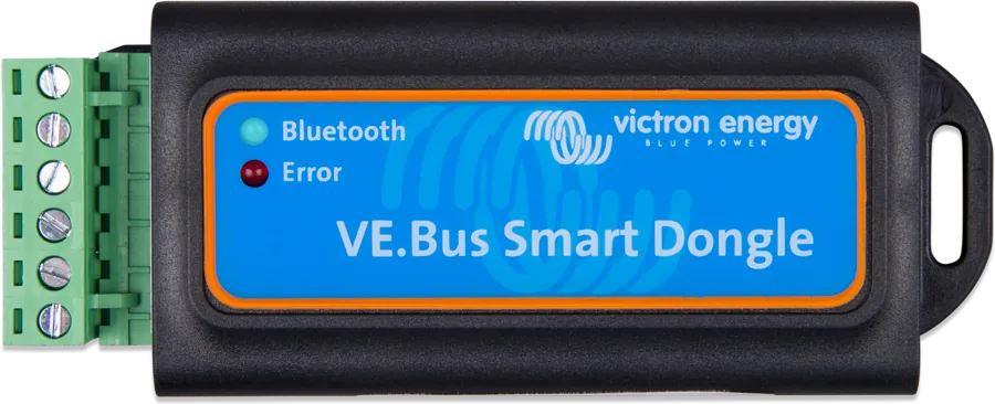
VE.Bus · 8 LEDs · GEN inputVE.Bus Smart dongle
Bluetooth to the inverter/charger: operating mode, current limit and monitoring in the VictronConnect app. The DMC panel still has priority over it. VE.Bus Smart dongle datasheet.
BluetoothHow to connect Digital Multi Control
The panel connects to the inverter/charger with one RJ45 UTP network cable — in a system with multiple devices, to any free RJ45 port. In most installations, nothing needs configuring after connection.
- Panel with four screwsIn a dry, clean place — not in rain or dust.
- RJ45 cable to the inverterStandard straight UTP cable, 0.3–30 m; in a system with multiple devices, to a free port.
- AC current limitUse the knob to set how much current may be drawn from shore power or the generator.
- Mode switchoff / charger only / on — without a phone or app.
Wall cut-out and one cable
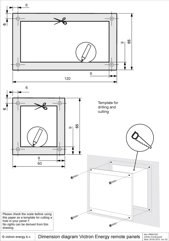
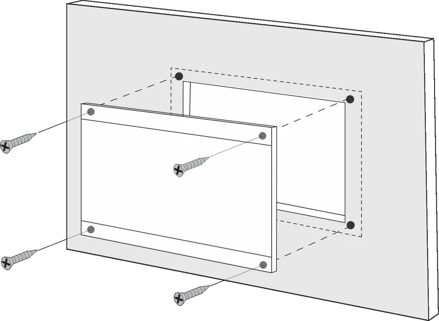
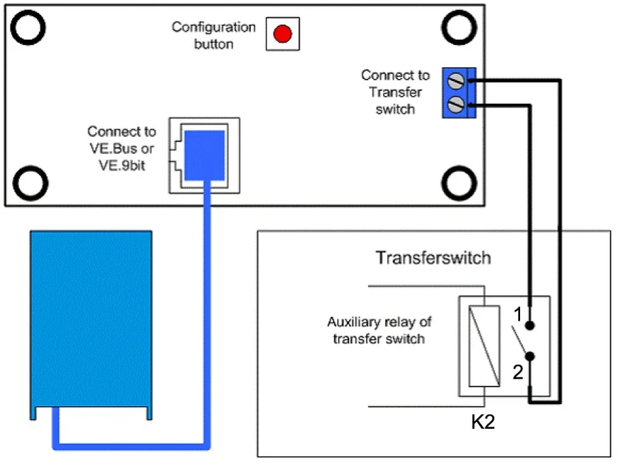
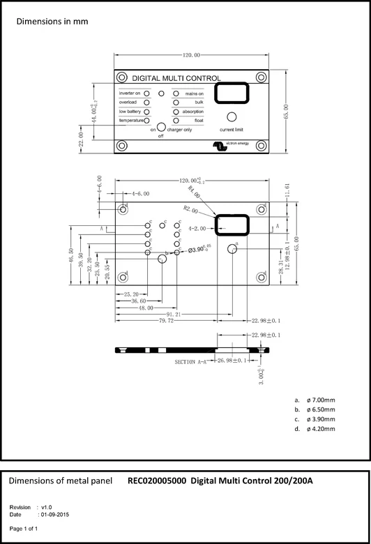
- Mounting: four screws in the marked positions, after cutting the opening to the template in the manual.
- Cable: a standard straight RJ45 UTP cable, 30 cm to 30 m long (sold separately), to the inverter/charger. In a system with multiple devices, to any free RJ45 port; in older systems before VE.Bus, to the main device.
- GEN input: 0.25–1.0 mm² wires, not included.
- Do not use the panel in rain, in a dusty environment, or where there is a risk of gas or dust explosion. In most installations, nothing needs configuring after connection.
Panel settings
- Entering configuration: hold the button on the back for about 4 s until the lower LED starts flashing. The knob changes the value, and the button moves to the next parameter — you must step through all of them, even if you are changing only one. During configuration, the inverters switch to “inverter only” mode.
- Generator current (for the GEN input): factory setting 16 A, range 0–198 A in 2 A steps. The manual recommends setting 70% of the generator’s rated current for 3,000 rpm generators and 90% for 1,500 rpm generators.
- Scaling factor applies only to older systems before VE.Bus — in VE.Bus systems leave it at 1.
- In a typical Quattro setup with the generator connected to AC1, the panel shows “AC1”, and the knob does not change the AC1 input limit. With the GEN function and an external switch, when the terminals on the back of the panel are shorted, “GEN” is displayed and the set generator limit is sent. To stop the alternating display of multiple inputs, set the upper limits of all inputs except one to zero.
Compatible devices
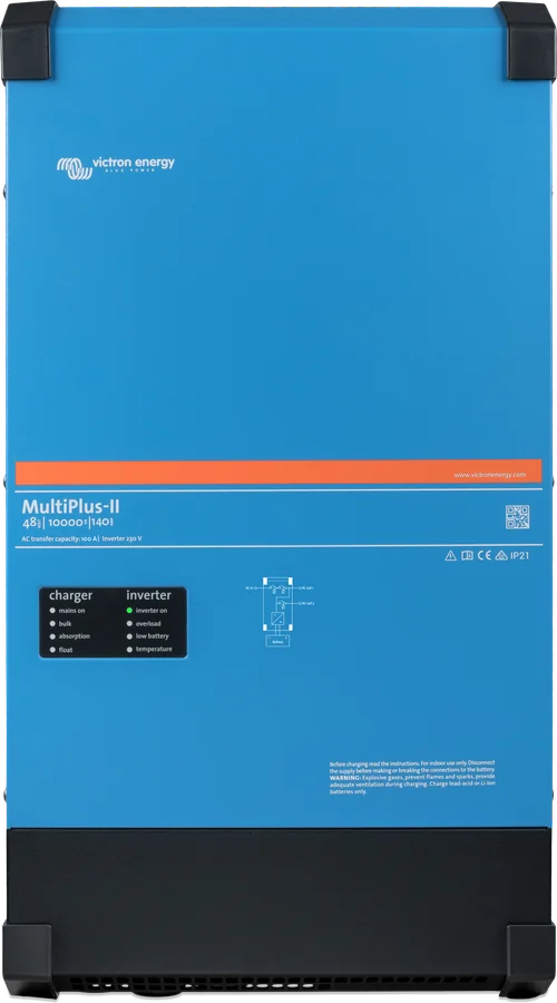
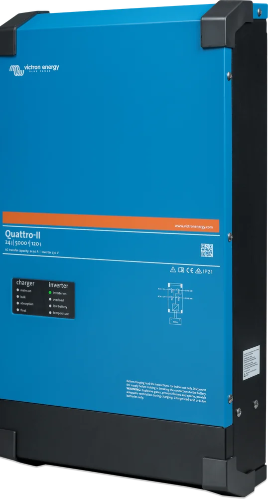
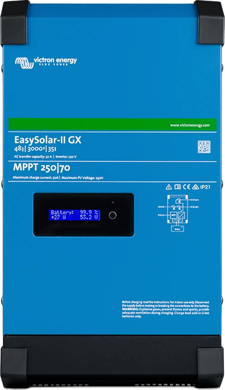
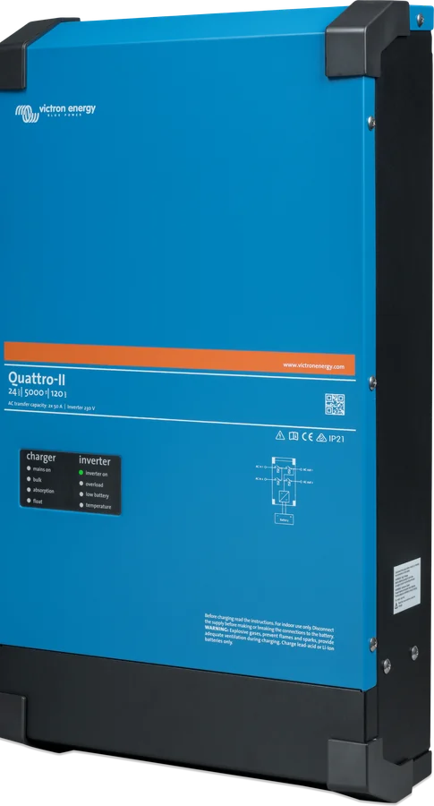
MultiCompact, MultiPlus, MultiPlus-II, MultiPlus-II GX, Quattro, Quattro-II, EasySolar, EasySolar-II GX and older systems before VE.Bus (firmware 15xxyyy, 17xxyyy, 18xxyyy; the change to VE.Bus happened between late 2007 and mid-2008).
Frequently asked questions about Digital Multi Control
Does the panel replace the VictronConnect app?
For everyday use, yes: you switch the system on and off, switch it to “charger only” mode and set the AC input current limit without a phone. Changing inverter settings still requires configuration software.
Which cable should you use to connect the panel?
A standard straight RJ45 UTP network cable, 30 cm to 30 m long — sold separately. In a system with multiple devices, plug the panel into any free RJ45 port (in older systems before VE.Bus — into the main device).
Does the panel work in a parallel and three-phase system?
Yes — it supports single, parallel, split-phase and three-phase systems. In most cases, nothing needs to be configured after connection.
What is the current limit knob for?
It sets the current limit the system can draw from the AC input — as much as the campsite hook-up or generator can supply. The inverter then makes up the missing power (PowerAssist).
Can the panel be mounted outdoors?
No. The manual forbids using it in rain, in dusty environments, or where there is a risk of gas or dust explosion.
How do you enter the panel configuration?
Hold the button on the back for about 4 seconds until the lower LED starts flashing. Change the value with the knob, and use the button to move to the next parameter — you must go through all of them, even if you are changing only one. During configuration, the inverters operate in “inverter only” mode.
What current limit should you set for a generator?
The factory setting is 16 A, and the range is 0–198 A in 2 A steps. The manual recommends 70% of the generator rated current for 3000 rpm units and 90% for 1500 rpm units.
The panel shows “AC1” and the knob does nothing — why?
This is normal for a typical Quattro setup with a generator on AC1 input: the knob does not change that input’s limit. With the GEN function and an external switch, after shorting the terminals on the back of the panel, the display shows “GEN” and the set generator limit is applied.
How do you stop the display from alternating between several inputs?
Set the upper limits of all inputs except one to zero — then the display will stop switching between them.

Content checked against Victron Energy documentation (datasheets and manuals) — as of 19 September 2026. Report a content error · Revision log