
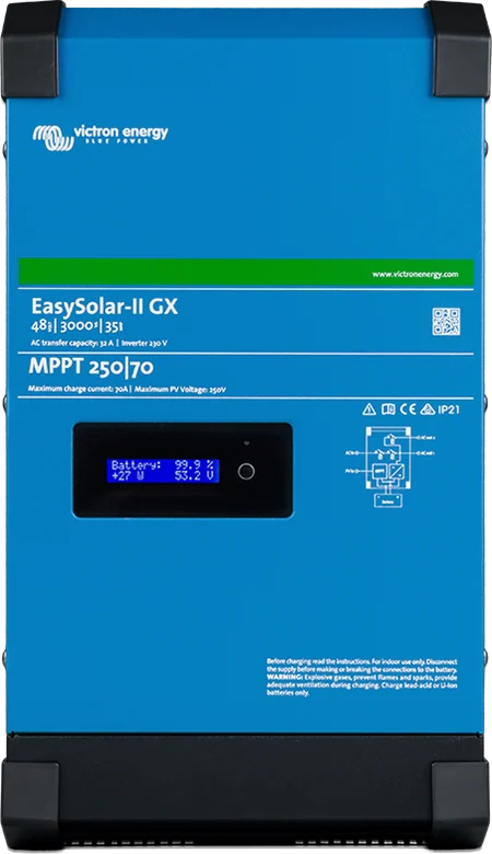
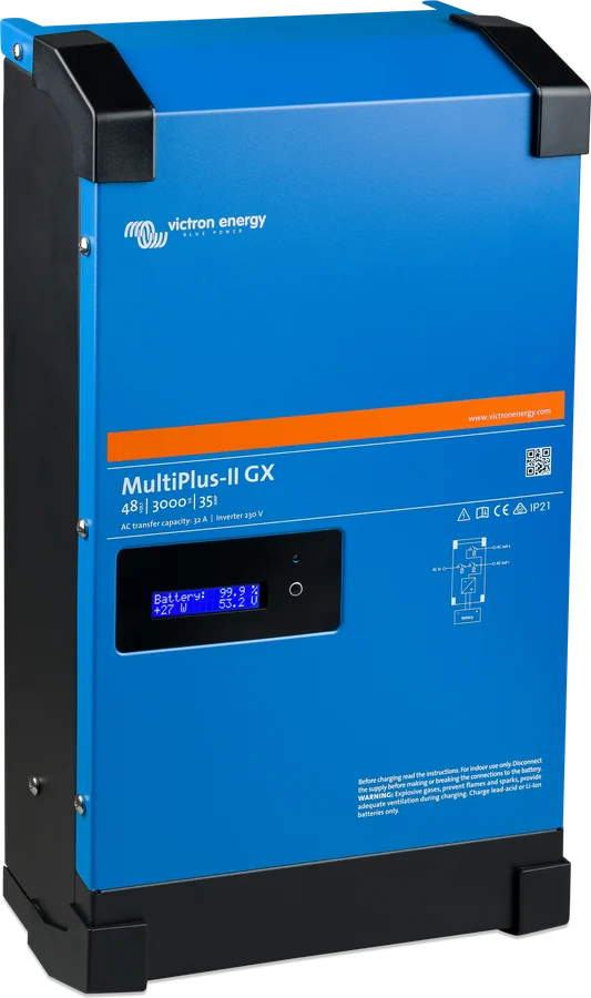
EasySolar-II GX — front with GX display and MPPT 250|70 marking
EasySolar-II GX
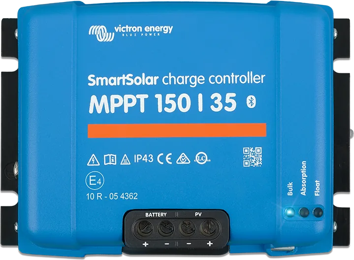
A MultiPlus-II inverter/charger, SmartSolar MPPT solar charge controller and GX device with display — factory-connected in one enclosure. The controller output is connected in parallel with the MultiPlus DC circuit, and the MultiPlus switch also controls the controller. Fewer cables and simpler installation than with separate devices.
- 24 V 3 kVA, 48 V 3 kVA, 48 V 5 kVA
- MPPT 250 V
- GX with display, Wi-Fi, Ethernet
- BMS-Can, VE.Direct, USB
Three devices factory-connected in one enclosure
EasySolar-II GX is a MultiPlus-II, SmartSolar MPPT solar controller and GX device with display — assembled and connected in the factory. The controller output is connected in parallel to the inverter DC circuit, and the MultiPlus switch also controls the controller.
Instead of three devices, three cable sets and a separate GX centre, you install one box: you connect the battery, panels, mains and loads. This is a solution for a cabin, off-grid system and energy storage, where the panels are part of the design from the start.
- 3 or 5 kVA inverter with 32 or 50 A charger and transfer switch,
- 250 V MPPT controller with 70 or 100 A current — up to 5,800 W of PV power,
- display, Wi-Fi and Ethernet: local monitoring and VRM portal access without a separate Cerbo GX.

What EasySolar-II GX can do
Inverter/charger
2,400 W continuous power at 25 °C in the 3 kVA versions and 4,000 W in the 5 kVA version; 5,500 or 9,000 W peak. Mains charging up to 70 A (24 V), 35 A (48 V 3 kVA) and 70 A (48 V 5 kVA).
250 V MPPT controller
250|70 and 250|100 versions. PV array power up to 2,000 W (24 V), 4,000 W (48 V 3 kVA) and 5,800 W (48 V 5 kVA). The controller starts when panel voltage exceeds battery voltage by 5 V.
Display and VRM
2 × 16 character screen — the button brightens it and switches views, after 5 minutes it dims. Data is also available via Wi-Fi and Ethernet in the VRM portal; the VRM ID is on the label in the connection compartment.
Internal communication
The GX device controls the inverter via VE.Bus, and the controller via VE.Direct — no cables need to be run between them.
BMS-Can and Aux inputs
The 500 kbit/s BMS-Can port is for compatible batteries with CAN BMS — this is not VE.Can, and it does not support VE.Can MPPT controllers or Lynx Shunt VE.Can. Aux in 1 and 2 accept the signals “allow charging” and “allow discharging”.
Three switch positions
0 — off, I — on, II — charger only. The switch and the remote terminals also switch off the GX device; switching off from the DMC panel, from the GX menu, or after an inverter alarm does not power it down.
PowerControl, PowerAssist, AC-out-2
By default, the AC input limit is 32 A (3 kVA) or 50 A (5 kVA), and UPS and PowerAssist are enabled. The second AC output disconnects when running on battery and reconnects about 2 minutes after the voltage returns.
Grid operation and expansion
The grid code is set in VEConfigure (changing parameters requires a password). Parallel and three-phase systems require identical units — up to 6 sets per phase, 18 in total; only one GX device can operate in the system, and delta configuration is not supported.
Three versions
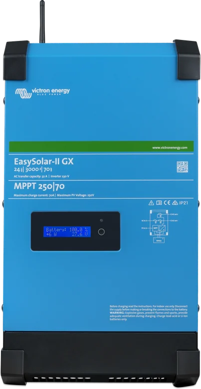
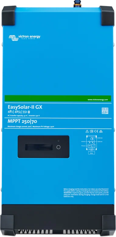
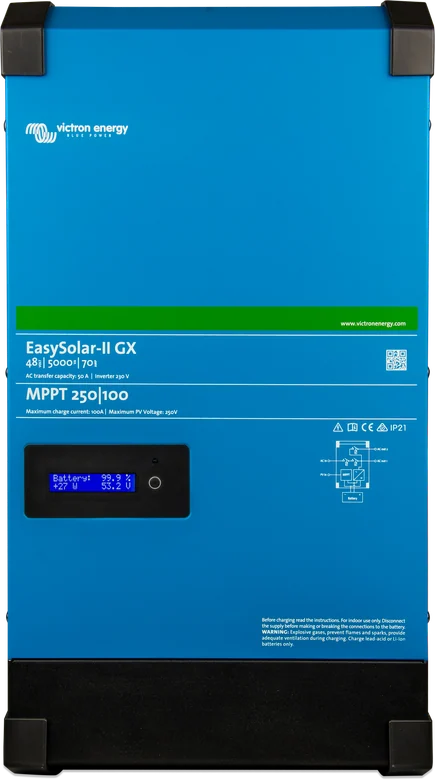
| 24/3000/70-32 MPPT 250/70 | 48/3000/35-32 MPPT 250/70 | 48/5000/70-50 MPPT 250/100 | |
|---|---|---|---|
| Continuous power 25 / 40 / 55 °C | 2400 / 2200 / 1700 W | 2400 / 2200 / 1700 W | 4000 / 3700 / 3000 W |
| Peak power | 5500 W | 5500 W | 9000 W |
| Inverter DC input | 19–33 V | 38–66 V | 38–66 V |
| Switch / AC input / AC-out-2 | 32 A | 32 A | 50 A |
| AC charging (max.) | 70 A | 35 A | 70 A |
| MPPT controller: PV current / power | 70 A / 2000 W | 70 A / 4000 W | 100 A / 5800 W |
| Absorption / float / storage (default) | 28.8 / 27.6 / 26.4 V | 57.6 / 55.2 / 52.8 V | |
| No-load consumption / AES / Search | 13 / 9 / 3 W | 11 / 7 / 2 W | 18 / 12 / 2 W |
| Max efficiency | 94% | 95% | 96% |
| Weight, dimensions (h × w × d) | 26 kg, 499 × 268 × 237 mm | 38.6 kg, 604 × 323 × 253 mm | |
According to the datasheet. The manual gives different mechanical and environmental data in several places (weight, dimensions, IP21/IP22 rating, temperature range, AC terminal cross-section) — check the data for your exact unit when planning the installation. 230 V ± 2% output, 50 Hz; charger input 187–265 V, 45–65 Hz. Recommended battery capacity: 200–800 Ah (24/3000 and 48/5000), 100–400 Ah (48/3000).
How to connect EasySolar-II GX
One enclosure contains the MultiPlus-II, SmartSolar controller and GX device. Leave installation to a qualified installer: voltage at the terminals can be dangerous even after switch-off. Simplified diagram.
- Disconnect powerBefore working, switch off AC and disconnect the battery; cover or disconnect illuminated panels.
- BatteryNegative first, then positive; select the DC fuse and cable cross-section according to the table, M8 terminals.
- Mains to AC-inTerminals from the left: N, PE, L. One earth connection, preferably at the battery.
- PV panelsVoc up to 250 V with margin for frost, array short-circuit current up to 35 A, M6 screws.
- LoadsAC-out-1 always, AC-out-2 only when mains is present.
- MonitoringGX display, Wi-Fi on your phone, VRM via Ethernet.
What is in the connection compartment
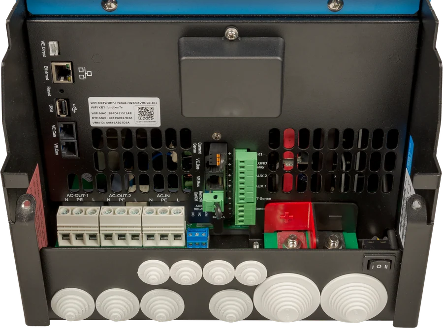
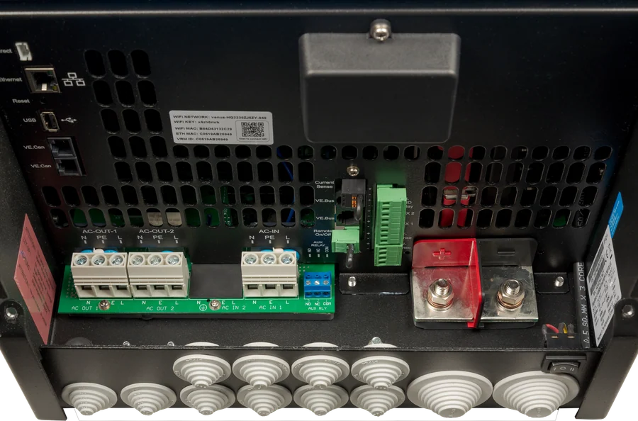
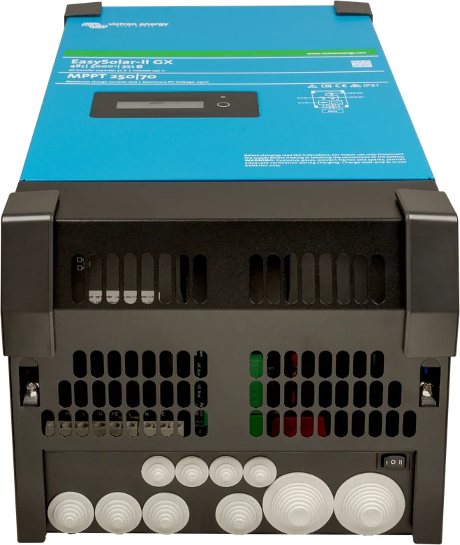
- Panels — PV connections are M6 screws, and array voltage must not exceed 250 V. Maximum array short-circuit current is 35 A.
- Battery — M8 screws. Before connecting, confirm polarity with a multimeter: reverse connection destroys the unit and is not covered by the warranty.
- AC terminals — terminal order from the left: N, PE, L. Do not swap N and L.
- Earthing — Class I device for TN networks; due to the high leakage current, provide additional earthing with a conductor of at least 10 mm².
- GX ports — Ethernet, Wi-Fi, USB, VE.Direct and BMS-Can, as well as Aux in 1 and 2 inputs and remote on terminals.
- The VRM ID sticker is in the connection compartment — it is worth photographing it before closing the cover.
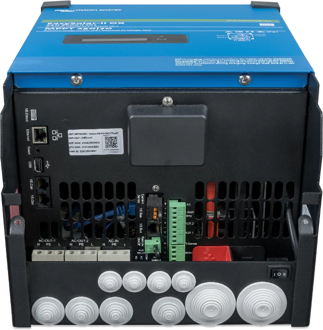
EasySolar-II GX, separate-device set or MultiPlus-II GX
EasySolar-II GX
Inverter, 250 V MPPT controller and GX device in one enclosure. Choose this when the panels are part of the design from the start and you want simple installation.
3 or 5 kVA · MPPT 250|70 or 250|100MultiPlus-II + SmartSolar + Cerbo GX
You can choose the separate devices freely: a more powerful controller, several trackers, a touchscreen display and VE.Can ports. 150/250 V controllers, Cerbo GX.
any configurationMultiPlus-II GX
The same inverter-to-GX connection, but without a solar controller — when there are no panels or they are charged by a separate controller. MultiPlus-II GX card.
inverter + GXIn a parallel or three-phase system, only one GX device can be used — in that case, choose the matching MultiPlus-II model for the EasySolar-II GX, or consider a MultiPlus-II without built-in GX.
Fuses, cables, rules
| Model | DC fuse | 0–5 m cables | 5–10 m |
|---|---|---|---|
| 24/3000/70 | 300 A | 50 mm² | 95 mm² |
| 48/3000/35 | 125 A | 35 mm² | 70 mm² |
| 48/5000/70 | 200 A | 70 mm² | 2 × 70 mm² |
- Installation and work on the unit should be carried out only under the supervision of a suitably qualified installer, in accordance with local requirements. Dangerous voltage may be present at the terminals even after switch-off — before working, switch off AC and disconnect the battery. Illuminated panels produce high DC voltage — cover them or disconnect them. There are no user-serviceable parts inside.
- Battery: before connecting, confirm polarity with a multimeter, use an insulated torque wrench and avoid shorting the cables. Connect negative first, then positive (a spark may occur). Reverse battery polarity will destroy the unit — the damage is not covered by the warranty.
- Earthing: system with earthed negative, one earthing connection preferably at the battery. Class I device for TN networks — AC terminals require a continuous protective conductor; due to the high leakage current, additional earthing with a conductor of at least 10 mm² is required. AC terminal order from the left: N, PE, L — do not swap N and L.
- The MPPT controller has no internal ground-fault protection — an external ground-fault detector (GFPD) is required; do not connect the controller to earthed PV strings.
- Dry, ventilated location, at least 10 cm of free space, preferably upright; never directly above batteries or where there is a risk of gas or dust explosion. In a parallel system, there must be no fuse or switch in the battery negative between units.
- The manual states in one place that the AC input must be protected by a max. 32 A circuit breaker, although the 48/5000 model has a 50 A input — choose the protective device to suit the model and power source. AC-out-2 switches off immediately when running on battery power and switches on about 2 minutes after AC returns to AC-in-1.
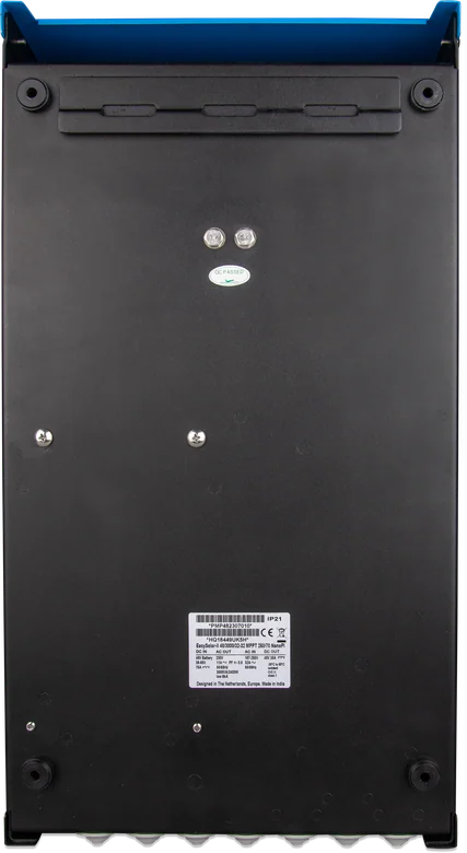
PV input
- Voc up to 250 V. The controller starts when PV voltage exceeds battery voltage by 5 V, and runs until it is at least 1 V higher.
- The manual gives a maximum PV short-circuit current of 35 A for the EasySolar-II GX and an example: from 144 cells in series (4 “12 V” panels or 2 “24 V” panels) up to 360 cells. At low temperature, the Voc of 360 cells may exceed 250 V, so you need to recalculate it. The open-circuit voltage of the panels (Voc) rises when the temperature falls below 25 °C — by the percentage per degree stated by the Voc temperature coefficient in the panel datasheet. With Victron BlueSolar panels (−0.35%/°C), at −20 °C this is about 16% more than in the catalogue.
- Reverse PV polarity: voltage drops, the controller heats up, but does not charge. The PV terminals are M6 bolts, the battery terminals are M8.
Panel selection: guide and MPPT calculator.
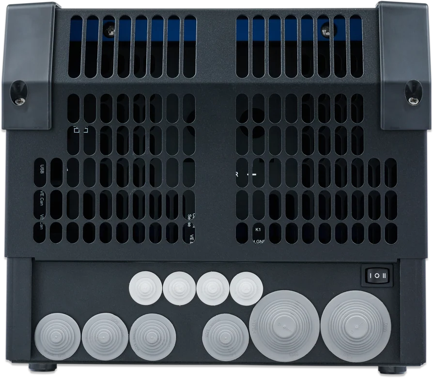
Built-in GX device
- 2 × 16-character display (the button brightens it and switches screens; it dims after 5 min); the same data are available via Wi-Fi on your phone. Access VRM via Wi-Fi or — better — Ethernet; the VRM identifier is on the sticker in the connection compartment.
- The GX controls the MultiPlus via VE.Bus, and the controller via VE.Direct. BMS-Can port (500 kbit/s) is used to connect compatible batteries with CAN-based BMS — it does not support VE.Can products (MPPT VE.Can, Lynx Shunt VE.Can). Aux in 1 and 2 ports can accept allow-to-charge and allow-to-discharge signals from a lithium battery BMS.
- Switch: 0 = off, I = on, II = charger only. Switching off with the switch or the remote terminals also switches off the GX; switching off from the DMC panel, from the GX menu or after an inverter alarm does not.
- Factory settings: 230 V / 50 Hz, standalone operation, earth relay enabled, profile for Victron Gel/AGM Deep Discharge batteries, AC input limit 32 A (3 kVA) or 50 A (5 kVA), UPS and PowerAssist enabled, WeakAC and dynamic current limiter disabled. Factory charging voltages may not suit the battery used; check them in the battery manufacturer’s documentation or with the supplier. Full inverter configuration requires VEConfigure (configuration in VictronConnect is limited); the controller is set up in VictronConnect. Only a properly qualified installer should change settings; the AC input must be disconnected when setting up the charger.
- For grid operation, the grid code is set in VEConfigure, and changing code parameters requires a password. If the local grid code is not supported, you must use an external certified interface device. Parallel and three-phase systems require identical units; up to 6 sets in parallel per phase (18 in total). There may be only one GX device in the system, and with the EasySolar-II GX you need to choose the matching MultiPlus-II model or consider a MultiPlus-II without built-in GX. Delta configuration is not supported.
Messages and common problems
A code appears on the display
The screen shows VE.Bus codes (inverter) and MPPT controller codes until the cause disappears. Meaning: VE.Bus codes and charger and MPPT codes.
No voltage on AC-out-2
Even after waiting, the AC input does not connect — this output works only when AC-in-1 is powered and returns about 2 minutes after it does. Troubleshooting: MultiPlus does not accept mains.
DC ripple too high
Ripple above 1.5 V RMS usually means loose connections or battery cables that are too thin. Tighten the terminals and check the cable cross-sections.
bulk protection message
The bulk phase has exceeded 10 hours, which may indicate a battery fault, for example a cell short circuit. Check the battery; the error is cleared by switching the unit off and on again.
Charging current drops to zero at the start of absorption
A faulty temperature sensor is possible, but so is an overheated battery (above 50 °C) or an internal cell short circuit.
Controller does not charge from the panels
Check whether the PV array voltage exceeds the battery voltage by at least 5 V at startup. With reverse panel polarity, the voltage drops, the controller heats up and does not charge.
PV insulation or earth fault
The controller has no internal earth fault protection — an external GFPD device is required. Do not connect the controller to earthed PV strings.
Annual inspection
Check that all connections are tight and protect the unit from moisture, oil, soot and vapours.
Frequently asked questions about EasySolar-II GX
What exactly is inside?
MultiPlus-II inverter/charger, SmartSolar MPPT controller and GX device with display — factory-connected. The controller output is connected in parallel with the MultiPlus DC circuit, and the MultiPlus switch also controls the controller.
Do I still need a Cerbo GX?
No. The built-in GX device shows data on the 2 × 16-character display and makes it available via Wi-Fi and the VRM portal. For VRM, Ethernet is better than Wi-Fi; the VRM identifier is on the sticker in the connection compartment.
Which panels can I connect?
PV Voc up to 250 V and short-circuit current up to 35 A. The controller starts when PV voltage exceeds battery voltage by 5 V. The manual gives an example from 144 to 360 cells in series — at low temperature, the Voc of 360 cells may exceed 250 V, so you need to recalculate it.
Will the BMS-Can port accept a VE.Can MPPT controller?
No. BMS-Can (500 kbit/s) is for compatible batteries with a CAN-based BMS — it does not support VE.Can products such as MPPT VE.Can or Lynx Shunt VE.Can.
What switches the whole unit off?
The switch (0 = off, I = on, II = charger only) and the remote terminals also switch off the built-in GX. Switching off from the DMC panel, from the GX menu or after an inverter alarm does not switch off the GX device.
How does it differ from the MultiPlus-II GX?
The EasySolar-II GX additionally has a built-in SmartSolar MPPT 250 V solar controller, factory-connected to the inverter DC circuit. MultiPlus-II GX is just an inverter with a GX device — you must connect the panels through a separate controller.
What fuses and cables on the battery side?
According to the manual: 24/3000/70 — 300 A fuse and 50 mm² cable for a 0–5 m run; 48/3000/35 — 125 A and 35 mm²; 48/5000/70 — 200 A and 70 mm². For 5–10 m, respectively 95, 70 and 2 × 70 mm².
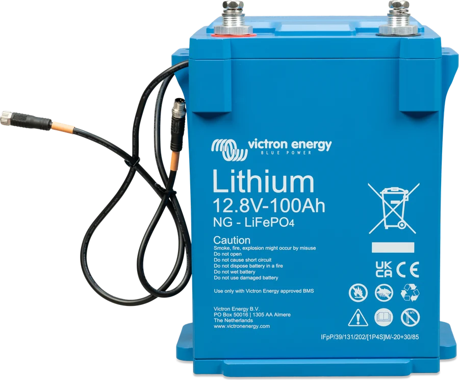
What battery should I choose?
The datasheet gives 200–800 Ah for the 24/3000 and 48/5000 models and 100–400 Ah for the 48/3000. The factory charging profile is set for Victron Gel and AGM Deep Discharge batteries — with a different battery, check the voltages in its documentation.
Can I connect several EasySolar-II GX units?
Parallel and three-phase systems require identical units — up to six sets per phase, eighteen in total. However, only one GX device can operate in the system, so the other units must be matching MultiPlus-II models. Delta configuration is not supported.
Where can I find the VRM ID?
On the sticker in the connection compartment. For the VRM portal, it is better to connect the device by Ethernet cable than over Wi-Fi.

Manufacturer documentation
Content checked against Victron Energy documentation (datasheets and manuals) — as of 19 September 2026. Report a content error · Revision log