
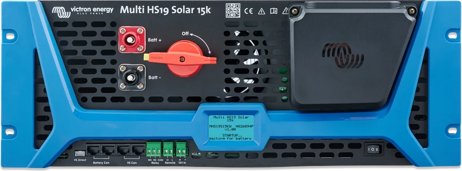
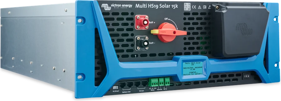
Multi HS19 Solar 15k — front panel with battery terminals, PV isolator, display and communication connectors
Multi HS19 Solar 15k
A three-phase 15 kW inverter/charger and four 8 kW MPPT solar charge controllers in one 19" 4U enclosure. It works with a 650–1000 V high-voltage battery with CAN communication and slides into the same cabinet as the batteries.
- 400 V · 3 phases
- 15 kW
- 4 × 600 V MPPT
- 650–1000 V battery
- 19" · 4U
A complete three-phase system in one drawer
Multi HS19 Solar combines a three-phase 15 kW inverter/charger and four independent MPPT solar charge controllers in a 19" 4U enclosure. It uses high-frequency technology — the manufacturer highlights low weight, high efficiency, quiet operation and low standby consumption.
The battery is a high-voltage 650–1000 V bank with its own BMS, connected via the Battery CAN port. Higher battery voltage means thinner DC cables. The unit slides into the same 19" rack cabinet as the batteries.
- manufacturer’s applications: backup power, peak shaving, grid export and off-grid,
- four 8 kW MPPT trackers, 32 kW of PV in total at 600 V,
- two AC outputs: uninterrupted AC-out-1 and AC-out-2 active only when external power is present.
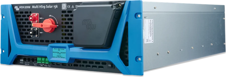

What the Multi HS19 Solar can do
15 kW inverter, 400 V, 3 phases
Continuous power 15 kW up to 40 °C, 22 A per phase. Peak 22 kW for 5 seconds (cold unit). Distortion below 3%.
Four 8 kW MPPTs
Four independent 100–600 V trackers, 32 kW PV in total. Partial shading detection searches for the global power point.
650–1000 V battery
Charging current up to 41 A (33 kW at 800 V), discharge up to 25 A. Charge control is handled by the battery BMS via CAN.
Two AC outputs
AC-out-1 is also powered from the battery. AC-out-2 disconnects during battery operation — for a boiler and other loads that should run only on mains.
PowerControl and PowerAssist
AC input current limit: the unit takes other loads into account and charges only with surplus. When the input is not enough, it adds power from the battery.
ESS without an assistant
ESS settings are available immediately in VictronConnect: modes with and without BatteryLife, “Keep batteries charged” and external control.
Display, Bluetooth, VE.Can
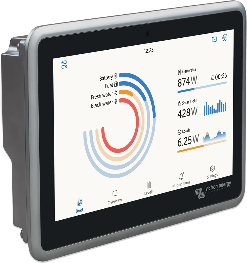
Backlit LCD, configuration through VictronConnect, VE.Can to the GX device and VRM portal, VE.Direct to GlobalLink 520.
Isolation and leakage monitoring
Protection: PV overvoltage and overcurrent, DC insulation resistance, residual current monitoring unit (RCMU), AC overcurrent.
Relay and remote on/off
Programmable 3 A relay up to 30 V DC (including alarm, low voltage, inverter operation, charging) and Remote terminals.
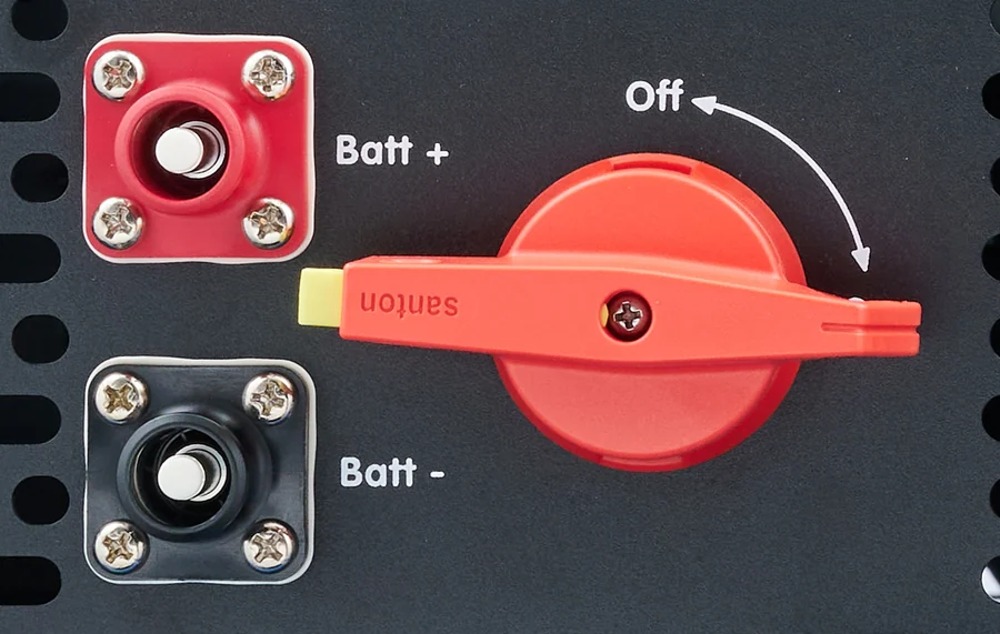
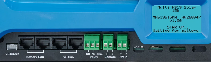
Main specifications
| AC and inverter | |
|---|---|
| AC voltage | 400 V ±10%, 3 phases (L1, L2, L3, N, PE) |
| Frequency | 50/60 Hz (range 45–65 Hz) |
| AC inputs / outputs | 1 input, 2 outputs |
| Input and pass-through current | max. 32 A |
| Apparent / rated power | 15 kVA / 15 kW |
| Continuous power up to 40 °C | 15 kW |
| Peak power | 22 kW for 5 s (32 A for 5 s) |
| Continuous current per phase | 22 A RMS |
| Max efficiency | 98% (drops at higher battery voltage) |
| No-load consumption | 50 W at 650 V battery voltage |
| PV and battery | |
|---|---|
| Trackers / strings | 4 / 4 (one string per tracker) |
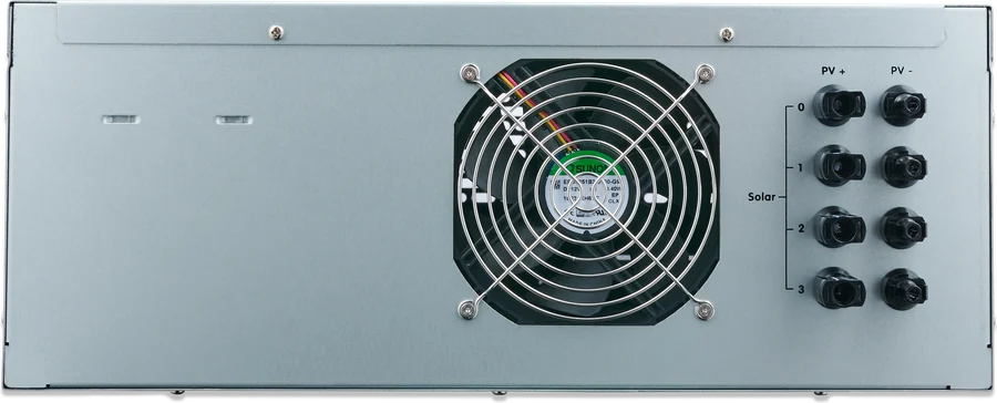
| PV voltage | Max. Voc 600 V, MPPT 100–600 V; wake-up with PV only supply: 300 V |
| String current | short-circuit 20 A, MPP 13.5 A |
| PV power | 8 kW per string, 32 kW total |
| MPPT efficiency | 99% |
| Battery voltage | 650–1000 V |
| Battery current | charge 41 A, discharge 25 A |
| Battery communication | CAN, Victron HV protocol |
| Parallel operation | no (future hardware revisions) |
- Enclosure
- 19", 4U, depth 71 cm, 26.5 kg
- Ingress protection
- IP20, indoor, in a controlled environment
- Operating temperature
- 0 to +60 °C, full power up to 40 °C
- Cooling
- forced-air cooling
- Altitude / humidity
- up to 2000 m, 95% non-condensing
- AC connections
- spring clamp: solid 0.2–10 mm², stranded 0.25–6 mm²
- DC / PV connections
- SurLok 5.7 mm / MC4 Stäubli
- Communication
- Battery CAN, VE.Can, VE.Direct, Bluetooth
When the inverter and PV are both delivering full power, the manufacturer provides for power derating — first PV, and in more severe cases also the inverter. Peak power and runtime depend on heatsink temperature; 22 kW for 5 s applies to a cold unit.
Where the Multi HS19 Solar sits in the system
Panels on four MPPT inputs, three-phase grid on the AC input, HV battery with BMS via CAN. Hover over a diagram element or tap it. Schematic overview.
- PV → 4 trackersOne string per input, Voc < 600 V, MC4 Stäubli connectors.
- Grid → AC-inThree-phase, protection up to 32 A, TN or TT grid.
- AC-out-1Loads powered even when the grid fails.
- AC-out-2Loads operating only on external supply.
- HV battery + CAN650–1000 V, BMS controls charging via Battery CAN.
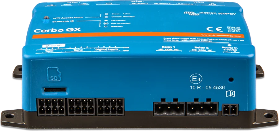
- GX (VE.Can)VRM monitoring and remote updates.
High-voltage batteries only with BMS and CAN
The Multi HS19 Solar does not work with a 48 V battery. You need a 650–1000 V battery bank with a BMS that communicates via the Battery CAN port. When communication is active, the BMS sets the charging voltage and current.
- Compatible: batteries with the Victron HV protocol; the manual introduction also lists Pylontech HV systems. The manufacturer provides the full list in a separate document (“HV battery compatibility list”).
- Below 650 V the inverter will not start — error 10. The battery must be charged from PV or externally.
- Loss of communication with the battery for more than 3 minutes, or a mismatch between the BMS voltage and the voltage at the terminals, is error 16.
- Replacement only with a battery of the same type and the same number of modules. Check with the battery manufacturer whether it can accept the system’s total charging current.
Multi HS19 Solar, Multi RS19 Solar or three MultiPlus-II?
Multi HS19 Solar 15k
One three-phase 15 kW unit with four MPPTs and a 650–1000 V HV battery. At present, no parallel operation and no generator support.
3 phases · 15 kW · HV batteryMulti RS19 Solar
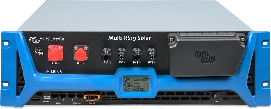
Single-phase 48 V in a 19" enclosure with two 450 V MPPTs; three units (one per phase) make a three-phase system. Multi RS19 Solar datasheet.
48 V · 6 kVA per phaseMultiPlus-II ×3
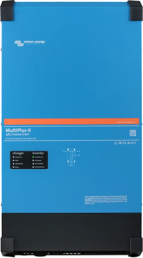
Three 48 V inverters in a three-phase system, with MPPT controllers on the DC side or PV inverters on the output. MultiPlus-II datasheet.
48 V · 3–15 kVA per phaseRack cabinet and high-voltage DC
Installation only by a certified installer. Never connect the battery directly — overcurrent protection between the battery and the unit is mandatory. Do not open the enclosure: there may be 1000 V DC inside even after shutdown. Before working, disconnect the battery isolator, PV isolator and the AC input and output breakers, then wait at least 5 minutes.
Cover the PV modules during installation. The PV inputs may still carry high voltage after the panels are disconnected. Do not connect or disconnect PV while the unit is on.
- Protect from water, rain and moisture; not in a dusty location or where there is a risk of gas or dust explosion; keep away from combustible materials such as cardboard.
- For indoor use only, in a standard 19" cabinet; airflow from front to back must not be blocked. At least 1U free space above and below the unit.
- Cabinet and surroundings must be non-combustible, with no direct sunlight. Not in air containing soot, dust or salt (e.g. generator exhaust), and not near flammable or corrosive gases.
- Never directly above lead-acid batteries. Keep out of reach of children and untrained persons.
- Excessive ambient temperature shortens service life, reduces charging current and peak power, and in extreme cases shuts down the inverter.
| Circuit | According to the manual |
|---|---|
| AC input | 32 A MCB or smaller (with weaker supply, correspondingly less), cable cross-section matched to the protection; do not swap L and N |
| AC terminals | spring clamp: solid 0.2–10 mm², stranded 0.25–6 mm²; strip 15 mm of insulation |
| Residual current devices | if required by regulations: separate type A RCD, at least 300 mA on the AC input (type B permitted where required by regulations); in AC circuits — RCDs resistant to DC components |
| Grid system | TN or TT; uninterrupted earthing via the PE of the AC input, otherwise earth the enclosure |
| DC cables | copper flexible conductor class 5 or higher (strands max. 0.4 mm), insulation min. 90 °C; the manual does not specify cable cross-sections or the DC fuse — protection between the battery and the device according to the battery manufacturer |
| PV | class A modules to IEC 61730, earthed frames; cables as for batteries — flexible conductor class 5; only original Stäubli MC4; reverse polarity of a string with short-circuit current above 20 A voids the warranty |
The battery, PV input and AC ports have no galvanic isolation. The device is protection class I — if you suspect an earthing fault, you must switch it off and secure it against restart. Damage from PV overvoltage (above 600 V) is not covered by the warranty.
Configuration in VictronConnect
All configuration is done in the VictronConnect app (iOS, Android, macOS, Windows — on Windows via a VE.Direct–USB interface). Bluetooth is enabled by default; the PIN is 000000 or the unique PIN from the sticker with the serial number — it is worth changing it. If you turn Bluetooth off, you can only turn it back on via VE.Direct–USB.
- Operating mode: On (default), Off, Inverter Only (AC input disconnected, charging only from PV) or Charger Only (without discharging the battery). The setting in the app can override the physical switch.
- Grid code: factory default “None”, i.e. no export to the grid. The presence of a country on the list does not mean certification — current certificates are in the manufacturer’s downloads section.
- ESS without installing an assistant; changes only in VictronConnect (the ESS menu in GX is limited, there is no control from VRM). Without AC input, i.e. off-grid, ESS provides no benefit.
- PE–N monitor disconnects the AC input if the voltage between PE and N is too high — switch it off only after ruling out installation faults.
- Display changes pages automatically: AC input, outputs, battery (voltage, current, SOC) and a separate page for each tracker.
What it does not support yet
The manual explicitly lists functions that the device does not yet have. It is worth knowing them before designing the system.
No parallel operation
For now, one unit in the system. The datasheet announces support in future hardware revisions, the manual — in future software updates.
No generator support
The manual says generator support has not yet been implemented, and the relay mode list does not include a generator mode — although the datasheet and relay description mention generator start/stop.
PV inverters on AC only with grid
PV inverters on the AC output are not currently supported in off-grid operation; they are supported when AC input is active.
ESS only with grid
Without AC input, ESS functions do not work — off-grid relies solely on PV and the battery.
Full power up to 40 °C
Above that, available power decreases; when PV and inverter are both at full power, PV is limited first.
Grid code not everywhere
The device does not have grid-export certification in all countries — before enabling export, check the certificate for Poland.
Most common faults
Typical situations from the manual. The full list of Multi HS19 Solar error codes — with descriptions and whether they clear automatically — can be found in the error codes: Multi HS19 Solar section.
Inverter does not start
Battery voltage below 650 V is error 10 — charge the battery from PV or externally. Without grid and without 12 V input, the device may lose communication, which makes off-grid start-up harder.
Cannot see the battery
No communication with the BMS for more than 3 minutes or incompatible voltage is error 16 — check the Battery CAN cable and battery compatibility (Victron HV protocol).
Switches off due to insulation or leakage
PV insulation resistance too low (error 41) or leakage above 30 mA (error 42) — check the wiring and insulation of the panels and battery.
Switches off when motors start
Starting currents of pumps and motors exceed the threshold (error 50, 52). After three restarts and another overload within 30 s, it switches off — reduce the load, turn it off and on again.
Overtemperature
Error 51 — restart after 30 s. Check the temperature in the cabinet, 1U clearance above and below the device and the fan outlets at the rear.
N–PE fault
Error 43: without grid, possible fault of the grounding relay; with grid — missing or incorrect PE connection, or L and N swapped.
Does not export energy to the grid
Factory default grid code is “None”, i.e. no export. Select the code for the country — after checking that the device has certification.
Switches to inverter too often
With a generator or unstable grid, the UPS function may need to be switched off.
Frequently asked questions about Multi HS19 Solar
Will Multi HS19 Solar work with a 48 V battery?
No. It requires a 650–1000 V high-voltage battery with BMS and CAN communication (Victron HV protocol). For 48 V rack batteries, there is Multi RS19 Solar.
How many panels can I connect?
Four strings — one per tracker — up to 8 kW each, 32 kW in total. String open-circuit voltage must be below 600 V even when the battery is in float stage, and short-circuit current must not exceed 20 A.
Can two devices be connected in parallel?
Not at present. The datasheet announces parallel operation in future hardware revisions, and the manual — in future software updates; it is therefore not known whether current units will get it.
Can I connect a generator?
The manual states that generator support has not yet been implemented. The datasheet mentions starting a generator with a relay at low battery state — before designing a generator system, check the current status with the distributor.
Can I export energy to the grid in Poland?
Export is enabled by selecting the grid code (factory default “None”). The manufacturer states that the device is not certified in all countries, and the presence of a code on the list does not mean certification — current certificates are on the manufacturer’s website.
Why is there a 12 V input?
The optional 12 V input maintains operation and communication and helps with start-up without grid (black start). Without it, the device works, but without another energy source it loses communication.
Which residual current device should I use?
If required by regulations — a separate type A RCD with a rating of at least 300 mA on the AC input; type B is permitted when required by regulations, but is not required by the manufacturer. The grid must be TN or TT.
How do I set ESS?
In VictronConnect, without installing an assistant. Modes: Optimized with BatteryLife and without, Keep batteries charged (default) and External control. For lithium batteries, the manufacturer recommends the mode without BatteryLife. Setting the “Grid setpoint” slightly above 0 W prevents accidental export to the grid.
Manufacturer documentation
Discrepancies in the documents: the datasheet describes the unit as ideal for off-grid use, while the manual’s relay datasheet and description mention generator start — yet the relay mode list has no generator mode, and the manual states that generator and PV inverter support in off-grid operation is not yet available. The datasheet says parallel operation will come in future hardware revisions, while the manual says it will come in software updates. The datasheet refers to Battery CAN ‘ports’, while the tables describe one port (a pair of sockets). The manual also contains a sentence about switching on by connecting Remote H to battery positive — with a 650–1000 V battery this looks like it was copied from another manual, so we do not repeat it.
Content checked against Victron Energy documentation (datasheets and manuals) — as of 22 September 2026. Report a content error · Revision log