
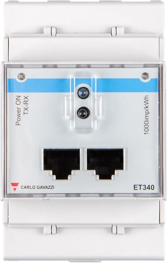
ET340 meter from the front — DIN-rail enclosure, Power ON and TX-RX LEDs, two RJ45 sockets
Energy meters ET112, ET340, EM540 and EM24 Ethernet
Carlo Gavazzi production meters that Victron sells under its own part numbers and supports in GX devices. They measure current directly — the phase conductor passes through the meter, without current transformers. They are most often used as a grid meter in an ESS system, but they can also measure a PV inverter, generator or a selected AC circuit.
- ET112 — 1 phase, up to 100 A
- ET340, EM540, EM24 — 3 phases, up to 65 A per phase
- RS485 or Ethernet (EM24)
- Zigbee optional
Measuring energy where the inverter cannot see it
An inverter/charger only knows the power flowing through it. When there are loads or a PV inverter before the inverter, the ESS system does not know how much energy is flowing from the grid and to the grid — that information is provided by the meter at the shore connection. The GX device reads it and uses it to control the inverter.
In a GX device, each meter is assigned one of four roles:
- grid meter (Grid meter) — control signal for ESS,
- PV inverter — generation from the grid-tie inverter,
- generator — energy from the AC generator,
- AC meter — selected load circuit (from GX software 2.80, any circuits, e.g. a heat pump).
Most PV inverters can be read directly in the Victron system, so a separate meter for the PV inverter is often not needed.
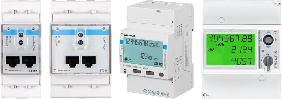
Which meter should you choose
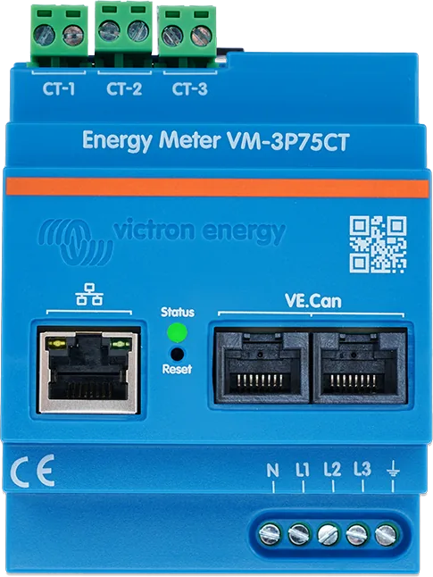
Start with the number of phases: a three-phase shore connection and a three-phase PV inverter require a three-phase meter. With a single-phase shore connection, a single-phase meter is enough, but a three-phase one will also work. If in a single-phase home you want to measure both the grid and the PV inverter at the same time, choose the ET340 (or EM540). If the current exceeds the direct measurement range, you need a meter with current transformers, for example VM-3P75CT.
ET112
Single-phase meter up to 100 A, without display — only an LED that flashes during communication. RS485, refresh 750 ms.
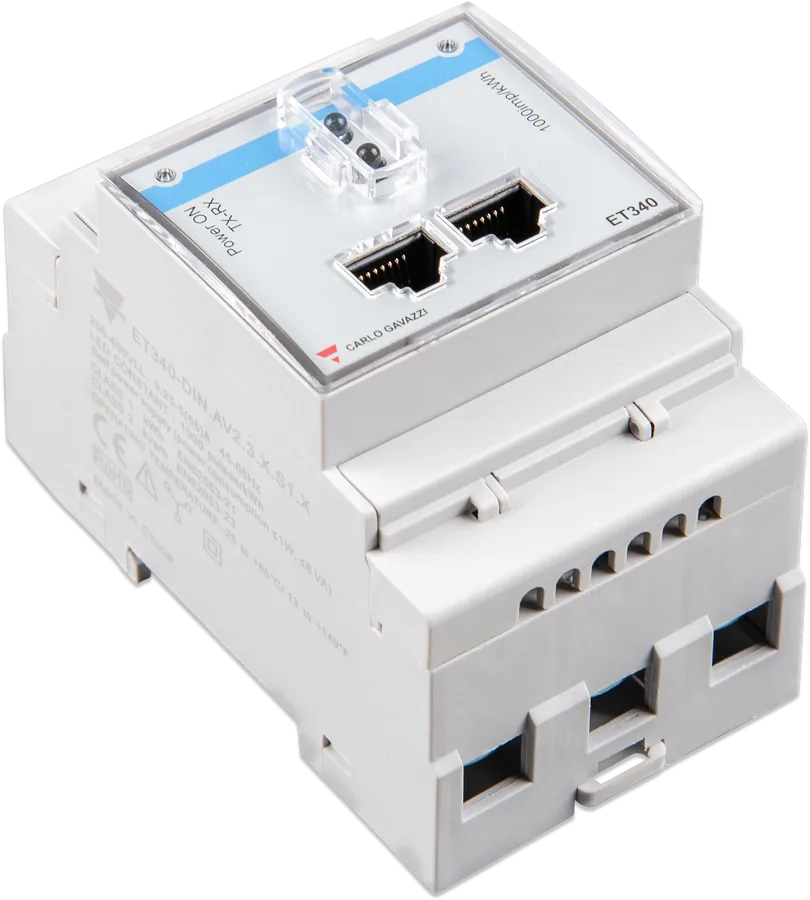
REL300100000ET340
Three-phase up to 65 A per phase, without display. Measures energy separately on each phase. In a single-phase system it measures the grid and PV inverter at the same time. Refresh 2000 ms.
REL300300000EM540
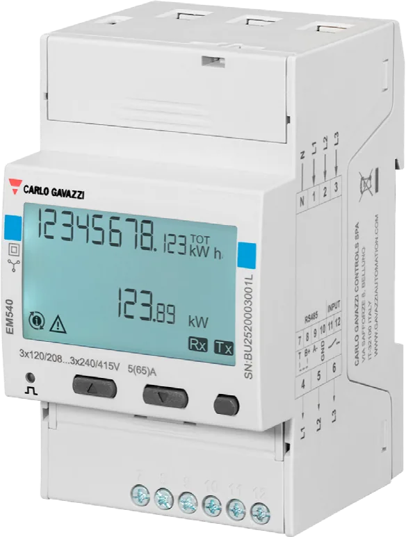
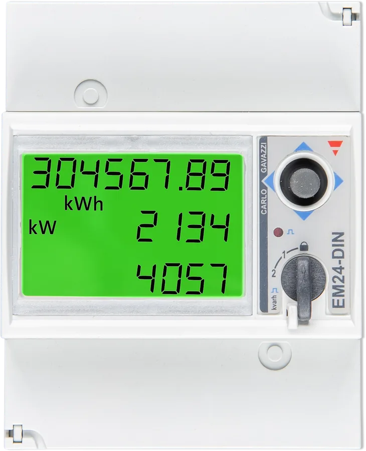
Three-phase up to 65 A per phase, with LCD display. Refresh 100 ms, reports power factor. Sums net energy from all phases.
REL200100100EM24 Ethernet
Three-phase up to 65 A per phase, with display. Connects to GX over the local network instead of an RS485 cable — useful when the distribution board is far from the GX, and the network is already there.
REL200200100VM-3P75CT
Victron meter with three 75 A current transformers, VE.Can and Ethernet, refresh 100 ms. For currents above 65 A per phase or when you do not want to cut the cables.
separate cardCurrent transformer for MultiPlus-II
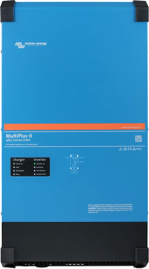
Split current transformer for the phase conductor — gives the MultiPlus-II a grid current measurement without an energy meter.
separate card| ET112 | ET340 | EM540 | EM24 Ethernet | |
|---|---|---|---|---|
| Victron part number | REL300100000 | REL300300000 | REL200100100 | REL200200100 |
| Carlo Gavazzi model | ET112DINAV01XS1X | ET340DINAV23XS1X | EM540DINAV23XS1X | EM24DINAV23XE1X |
| Phases | 1 | 3 | 3 | 3 |
| Max current | 100 A | 65 A per phase | 65 A per phase | 65 A per phase |
| Measurement | direct (conductor through meter) | |||
| Display | no | no | LCD | LCD |
| GX communication | RS485 | RS485 | RS485 | Ethernet |
| Zigbee (wireless) | yes | yes | yes | no |
| Refresh | 750 ms | 2000 ms | 100 ms | 600 ms |
| Power factor | no | no | yes | no |
| Grid + PV inverter in a 1-phase system | no | yes (L1 + L2) | yes (L1 + L2) | no |
| RS485 terminals (Data+ / Data− / GND) | 4 / 5 / 6 | 8 / 9 / 10 | 8 / 9 / 10 | — |
Refresh means how often the meter has a new value in its registers; the read itself via GX at 9,600 baud takes an additional 180–250 ms. GX also supports meters not sold by Victron (bought from Carlo Gavazzi or ABB): EM111, EM112, selected EM330, EM340, EM530, EM24 RS485, EM24 with current transformers (EM24DINAV53XE1X / EM24DINAV53DISX), and ABB B21, B23 and B24 — ABB without Zigbee support.
ET340 or EM540 — the difference in phase summing
The two three-phase meters calculate imported and exported energy differently:
- ET340 counts import and export separately on each phase, and gives the total as the sum of those values (arithmetic method).
- EM540 (and EM24) calculates energy from the sum of the power of all phases — import on one phase and export on another cancel each other out (vector method, net summing). EM24, EM5xx and ABB meters use only this method.
Choose a meter so that it counts the same way as the utility meter. If the utility bills the net sum across all phases (this is most common in Germany and Austria), EM540 will give readings that match the bill. Victron ESS phase compensation works the same way. Confirm the billing method with your utility.
The ESS manual points to the EM24 for the same purpose — see troubleshooting ESS imports from the grid. Victron says it will continue to sell both ET340 and EM540.
Grid meter in an ESS system
Three-phase meter at the shore power connection, before the inverter/charger and loads; read via an RS485 to USB interface. Installation in the distribution board must be carried out only by a qualified electrician. Simplified diagram.
- Meter at the shore power connectionBefore the inverter/charger and before the loads that should be visible to ESS.
- Voltage measurement315 mA fuse, if required by local regulations.
- RS485 to USBData+, Data−, GND to the meter terminals; the other end to the GX device’s USB port.
- Role in GXSettings → Energy meters: “grid meter” role and phase type.
- ESSGX controls the MultiPlus based on the meter reading.
AC-side connection
A direct-connected meter is in the current path — the full circuit current flows through its terminals. It must be installed only by a qualified electrician, after the power has been switched off.
- The role determines the wiring. Grid meter, PV inverter, generator or AC meter — you set this role in GX, but it determines how the meter is wired and how GX shows the data.
- 315 mA fuse in the measurement circuit where Victron diagrams show “Fuse” — if required by local regulations.
- Direction when measuring a PV inverter: on ET340 and EM540 terminals 1, 2 and 3 on the inverter side, on EM24 terminals 1, 4 and 7 — otherwise power and energy will be shown with the wrong sign.
- Single-phase PV inverter in a three-phase installation: all three phases to the phase terminals on the grid side (EM540: 4, 5, 6; EM24: 3, 6, 9), and the PV inverter phase to terminal 1, 2 or 3 (EM24: 1, 4 or 7) — on the selected phase.
- Three-phase meter as a single-phase grid meter: grid on L1 (terminal 1). On EM24, also a jumper between terminals 1 and 4 — not needed in the AV2 version.
- Grid and PV inverter on one meter (ET340 and EM540 only, single-phase installation): grid on L1, PV inverter on L2. EM24 cannot do this — use an EM540 or two single-phase meters.
- Three ET112 units cannot replace a three-phase meter — in a three-phase installation, use a proper three-phase meter.
RS485, Zigbee or Ethernet
RS485 to USB — wired
ET112, ET340 and EM540 are connected to GX with an RS485 to USB interface (1.8 m or 5 m cable). The meters are factory set for GX — they work straight away after connection. Orange wire = Data+, yellow = Data−, black = GND; red, green and brown are not used.
Extension up to 100 m
Twisted pair, e.g. CAT5: Data+ to orange, Data− to white/orange, GND to brown — Data+ and Data− in one pair. Use a shielded cable, away from AC and DC cables. Above 10 m, shorten the factory interface cable to max. 20 cm; if the length is changed, 120 Ω terminators may be needed at both ends.
Zigbee — without cable
A pair of converters: Zigbee to USB for GX (powered from GX) and Zigbee to RS485 at the meter — this one needs a 12 V DC power supply. When pairing, only the converter at GX should be powered. New converters (ASS300420100/200) are not compatible with the old ones and require Venus OS 2.54 or later.
Ethernet — EM24
The EM24 Ethernet connects to the local network where GX can see it. The switch on the front of the meter must be in the unlocked position so GX can configure it. If the network fails, the ESS system goes idle (passes through the grid).
Several meters
The simplest way: each meter on a separate RS485 to USB interface, in a separate GX USB port. Two EM540 units can share one interface if you change the Modbus address of the second to 2 (from the meter menu) — only addresses 1 and 2 are supported.
Isolated interface
Victron interfaces are not isolated and in most installations that is sufficient. Where isolation is needed, Victron recommends the USB485-STIXL from Hjelmslund Electronics.
The section on multiple meters says that ET112 units can be connected in parallel on one interface after changing the Modbus address with Carlo Gavazzi UCS Desktop. The FAQ in the same manual notes that ET meters without a display on a shared RS485 bus are not supported by Victron. Safer option: a separate interface for each meter.
Role and phase type
- Find the meterAfter connection and power-up, the meter appears in Settings → Energy meters.
- Set the roleGrid meter, PV inverter, Generator or AC meter — according to how the meter is wired.
- Set the phase typeSingle phase or Multi phase. For ET112, GX shows only “Single phase”.
- Grid and PV on one meterOn ET340 or EM540 as a grid meter: phase type “Single phase” and “PV inverter on phase 2” enabled.
- Check the readingThe meter appears in the device list with the power of each phase; in the Device menu you can give it a custom name, and in Setup you can change the role.
Most common questions about energy meters
Can I use a meter from another brand or a Fronius Smart Meter?
No. GX supports only the meters on Victron’s list — in addition to the four on this page, also selected Carlo Gavazzi models (EM111, EM112, EM330, EM340, EM530, EM24 RS485) and ABB (B21, B23, B24). Fronius Smart Meter is not supported.
Can three ET112 meters replace a three-phase meter?
No. In a three-phase installation, you must use a three-phase meter (ET340, EM540, EM24 or VM-3P75CT).
Can these meters be bought directly from Carlo Gavazzi?
Yes — Victron gives the Carlo Gavazzi part numbers for exactly that reason. The exact model matters, for example EM540DINAV23XS1X.
I have currents above 65 A per phase — what then?
Meter with current transformers: VM-3P75CT or VM-3P5A. GX also supports EM24DINAV53DISX and EM530DINAV53XS1X with current transformers — Victron does not sell them; you buy them from Carlo Gavazzi.
Ethernet or RS485?
Ethernet (EM24, VM-3P75CT) uses the existing network instead of running an RS485 cable from the distribution board to GX. However, it only works when the network is working — if it fails, ESS goes idle. The most reliable option is a direct connection: RS485 or VE.Can in VM-3P75CT.
Can a GX meter replace a Victron inverter?
No. Meters complement a system with a Victron inverter/charger. A GX device with a meter on its own is suitable for measuring house or heat pump consumption before designing an installation, but meters cannot replace communication with battery inverters from other brands.
Why do ET112 and ET340 have RJ45 sockets if they are not used?
These are Carlo Gavazzi RS485 bus sockets. With the Victron RS485 to USB interface, Victron recommends connecting to the screw terminals under the sockets. Do not connect the meter’s RJ45 sockets to VE.Bus or VE.Can.
What does the LED on the ET112 and ET340 do?
ET meters have no display — the LED flashes when communication is in progress. For this reason, you do not change the Modbus address on the meter itself.

Manufacturer documentation
- Energy Meter Selection Guide — selection guide and meter tablevictronenergy.com · PDF · EN
- Energy Meter ET112 manual (rev 07)victronenergy.com · EN
- Energy Meter ET340 manual (rev 07)victronenergy.com · EN
- Energy Meter EM540 manual (rev 07)victronenergy.com · EN
- Energy Meter EM24 Ethernet manual (rev 07)victronenergy.com · EN
Content checked against Victron Energy documentation (datasheets and manuals) — status as of 23 September 2026. Report an error in the content · Correction log