
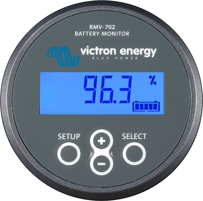
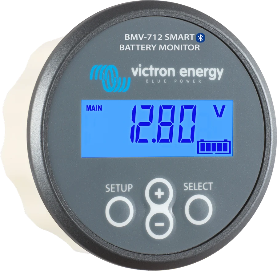
BMV-702 front view — grey panel, display showing state of charge 96.3% and SETUP, plus, minus, SELECT buttons
BMV-700 and BMV-702
Battery monitors with a round display and 500 A shunt. They measure voltage and current, calculate state of charge (SoC), consumed amp-hours and remaining runtime, store history, and have an audible alarm and a relay — for example, to start a generator. The BMV-702 has an additional input: second battery, bank midpoint or temperature. Unlike the BMV-712 Smart, they do not have built-in Bluetooth.
- 6.5–95 V
- 500 A / 50 mV shunt
- 60 V / 1 A relay
- VE.Direct
- BMV-702: Aux input
Battery fuel gauge
You cannot tell how much energy a battery has just by looking at it, and its lifespan is shortened by undercharging, overcharging and excessively deep discharges. The BMV calculates the current flowing into and out of the battery, takes charging efficiency and the Peukert effect into account, and on that basis shows state of charge in percent and the time remaining until the set discharge level is reached.
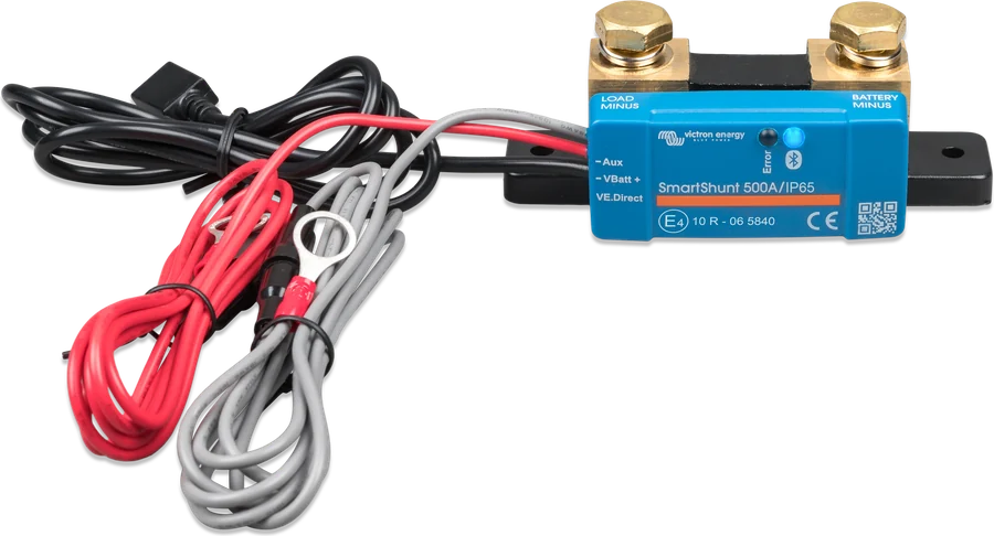
All current wiring is connected at the shunt, and a thin RJ12 cable runs to the panel — you can mount the panel where you can see it: in a cupboard, on the dashboard, in the cockpit.
- voltage, current, power, consumed Ah, state of charge and remaining runtime,
- history: deepest and average discharge, number of cycles, energy consumed and returned,
- alarm (buzzer and flashing backlight) and programmable relay,
- VE.Direct port to GX and VRM, for the VictronConnect app or your own integration.
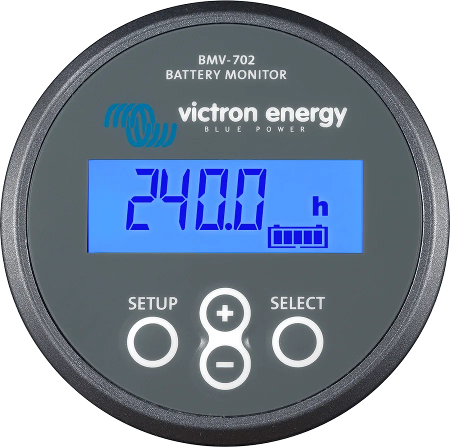
BMV-700, BMV-702 or BMV-712 Smart
BMV-700
Single-battery monitor: voltage, current, SoC, runtime, alarm and relay. No additional input. One fused wire included.
BAM010700000BMV-702 and BMV-702 BLACK
The same as the BMV-700 plus an Aux input: second battery voltage, bank midpoint or temperature (with a sensor). BLACK differs only by the black panel.
BAM010702000 / BAM010702200BMV-712 Smart
BMV-702 functions and built-in Bluetooth — no dongle needed for the app.
separate card| BMV-700 | BMV-702 / 702 BLACK | BMV-700H | |
|---|---|---|---|
| Supply voltage | 6.5–95 V DC | 6.5–95 V DC | 60–385 V DC |
| Aux input (second battery, midpoint, temperature) | no | yes, 6.5–95 V DC | no |
| Temperature measurement | — | −20…+50 °C, with ASS000100000 sensor | — |
| Current consumption (backlight off) | < 4 mA — approx. 2.9 Ah per month at 12 V and 2.2 Ah at 24 V | ||
| Battery capacity | 1–9999 Ah | ||
| Relay | 60 V / 1 A, normally open (operation can be reversed) | ||
| Accuracy (500 A shunt) | current ±0.4%, voltage ±0.3%; resolution 0.01 A, 0.01 V, 0.1 Ah, 0.1% SoC, 1 min | ||
| Panel | front ⌀ 63 mm, bezel 69 × 69 mm, body ⌀ 52 mm × 31 mm, IP55 (not for outdoors) | ||
| Operating temperature | −40…+50 °C | ||
| Communication | VE.Direct (Bluetooth via VE.Direct Bluetooth Smart dongle, USB via VE.Direct–USB interface) | ||
The BMV-700H appears in the series datasheet (60–385 V DC installations), but it is not on Victron’s product list — it is suitable only for installations with a grounded negative, because the panel is not isolated from the shunt. The BMV-700 and BMV-702 kit includes: panel with mounting sleeve, 500 A shunt, 10 m RJ12 cable, square bezel, four screws and a 1 A time-delay fused wire (BMV-702: two fused wires).
Shunt on the negative, panel where you look
Only the shunt is on the battery negative — all loads and chargers connect to its other side. The battery positive does not pass through the shunt. Conceptual diagram.
- Battery negativeOn the M10 screw of the “BATTERY ONLY” side — nothing else on the battery negative.
- Installation negative“LOAD AND CHARGER” side: all loads, inverters and chargers; max. 21 Nm.
- +B11 A fused wire: ferrule in +B1, M10 ring terminal on battery positive.
- RJ12Cable from shunt to panel — the panel powers up.
- +B2 (BMV-702)Second battery, midpoint or temperature sensor.
Second battery, midpoint or temperature
Starter battery
The negative of the second battery must be on the LOAD AND CHARGER side of the shunt (common negative). The second fused wire: ferrule in +B2, M10 ring terminal on the positive of the second battery. The alarm and relay can respond to its voltage.
Bank midpoint
In a 24 V or 48 V bank with batteries connected in series: +B2 to the midpoint. The BMV calculates the voltage imbalance between the halves and warns you about a weak battery or cell — see details below.
Battery temperature
Temperature sensor for the BMV-712 and BMV-702 (sold separately): black wire to +B2, red wire to +B1, ring terminal to battery positive. Replaces the fused wires. The sensor from a MultiPlus will not work.
You select the input function in the wizard after first start-up or in setting 69 (Aux input): Starter battery, Midpoint, Temperature or None.
Generator start, load disconnect, alarm
The relay has COM and NO contacts (60 V / 1 A) on the back of the panel. By default, it closes when state of charge falls below 50%, and opens when it rises to 90%. Other conditions are disabled by default; enable them by setting thresholds above zero.
- Relay mode (setting 11): DFLT — every enabled condition controls it; CHRG — closes at low SoC or low voltage and opens when both return above the thresholds (generator start/stop); REM — controlled via VE.Direct.
- Minimum closing time 0–8 h (for example a minimum generator run time) and opening delay 0–500 min (for example longer charging).
- Voltage conditions (low, high; on the BMV-702 also starter battery voltage, temperature and midpoint) operate after the threshold has been exceeded for 10 s.
- Invert relay: normally closed relay — slightly increases BMV current consumption.
Alarms: low SoC, low and high voltage, and on the BMV-702 also starter battery, midpoint and temperature. An alarm is the buzzer, flashing backlight and icon; pressing the button acknowledges it. The alarm is also visible in VictronConnect, on GX and in VRM.
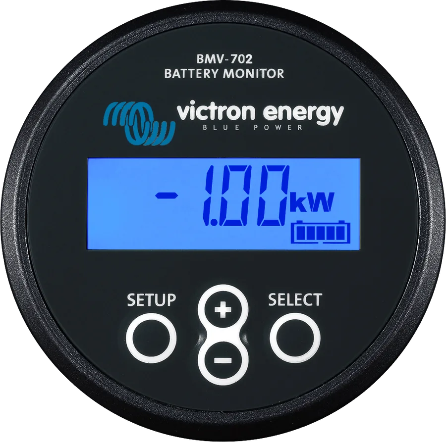
Wizard, synchronisation, lithium battery
- First-start wizardBattery capacity (factory default 200 Ah; for lead-acid batteries the 20-hour capacity C20), and on the BMV-702 also the Aux input function. You must finish the wizard before other settings.
- System voltageBMV detects it automatically: below 18 V — 12 V, 18–36 V — 24 V, above 36 V — 48 V. It will not detect a 32 V system — set the charged voltage manually then.
- Charged voltage0.2–0.3 V below the charger float voltage; for lead-acid batteries 13.2 / 26.4 / 52.8 V (12 / 24 / 48 V).
- Synchronised startSetting 70: ON — after switch-on SoC = 100%; OFF — SoC unknown (“---”) until the first synchronisation.
Synchronisation sets SoC to 100% when, at the same time: voltage exceeds “Charged voltage”, charging current drops below “Tail current” (factory default 4% of capacity, e.g. 8 A for 200 Ah) and this lasts for “Charged detection time” (factory default 3 min). Manually: hold + and − for 3 s, or press “Synchronise” in the app.
Peukert exponent 1.05 (lead-acid 1.25), charge efficiency 99%, Discharge floor 10–20% and — if the charger finishes charging at a set current — a higher Tail current. Unless the battery manufacturer recommends otherwise.
The BMV continually draws current from the battery. A discharged lithium battery can be permanently damaged even by a small current — for a long stop, disconnect the BMV positive supply or switch off the whole battery with a disconnect switch.
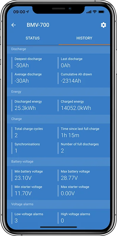
How to detect a weak battery in a series bank
One faulty battery or cell in a 24 V or 48 V bank can damage the others: it will not charge fully itself, and will overcharge the others. The BMV-702 compares the voltages of the upper and lower half of the bank and shows the deviation as a percentage. The deviation increases at the end of bulk charging, at the end of deep discharge and at high currents.
- Alarm threshold: no more than 2% (for gel and AGM batteries — above this the upper battery is overcharged). In a 48 V bank made of 12 V batteries, the effect of one battery is half as large, so the threshold can be lower.
- Delay: alarm after 5 minutes above the threshold; at twice the threshold — after 10 seconds.
- Alarm during charging: in a new bank this is usually different state of charge of the batteries. When the deviation exceeds 3%, stop charging and charge the batteries separately or reduce the charging current significantly.
- Alarm during discharge: at the end of a deep discharge this is normal. If it appears much earlier, one battery has lost capacity or has a higher internal resistance.
- Wiring: when measuring the midpoint, always use busbars and cables to the busbars of the same length. Do not connect the midpoints of parallel branches unless you monitor the bank and respond to alarms.
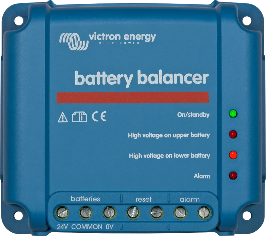
A Battery Balancer can be a permanent solution for lasting differences. The documentation is inconsistent: the BMV manual says the balancer switches on above 27.3 V and draws up to 0.7 A, while the BMV-700 series datasheet says above 27 V and up to 1 A.
Most common problems
Panel does not work
Check the fuse in the +B1 wire, the wire itself and the terminals. With the temperature sensor: sensor eye on battery positive, red to +B1, black to +B2, correct sensor (not from the MultiPlus).
Current has the wrong sign
Charging should be positive, discharging negative. If it is the other way round — swap the negative wires on the shunt. The same fault gives SoC permanently 100%.
SoC too high
One of the loads or the charger has its negative connected directly to the battery or to the BATTERY ONLY side — its current bypasses the shunt.
SoC “---” or does not reach 100%
The monitor is not synchronised. Charge the battery fully or synchronise manually; check Charged voltage, Tail current and Charged detection time.
Synchronisation too early
In solar installations: raise Charged voltage just below the absorption voltage (e.g. 14.2 V at 14.4 V), lengthen the detection time or reduce Tail current.
No starter battery reading
Both batteries must have a common negative, and the starter battery negative must be on the LOAD AND CHARGER side of the shunt. Check the fuse in the +B2 wire.
Current with no load
Switch off all loads and perform a zero current calibration (Zero current calibration) or set a current threshold (Current threshold).
Cannot change settings in the app
Update the BMV firmware in VictronConnect. Factory reset on the panel: SETUP + SELECT for 3 s (when Lock setup = OFF).
Documentation inconsistencies: the synchronisation example in section 5.7 gives 13.2 V, while section 10.3.4 gives 13.8 V; the temperature sensor terminal is described once as M10 and once as M8. The manual gives 1.5 m fused wires, the datasheet — 2 m.
Most common questions about BMV-700 and BMV-702
Does the BMV-702 have Bluetooth?
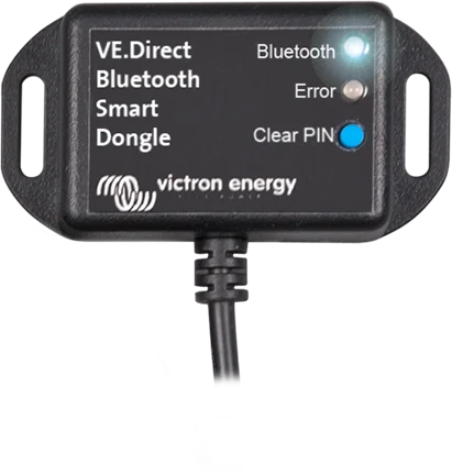
No. For VictronConnect you need a VE.Direct Bluetooth Smart dongle (Android, iOS, macOS; open-field range about 20 m, one phone at a time) or a VE.Direct–USB interface (also Windows). Built-in Bluetooth is in the BMV-712 Smart.
Can I use a larger shunt?
Yes — up to 9,999 A and 75 mV, for example 1,000, 2,000 or 6,000 A. The 500 A shunt board is bolted to the new shunt (note the orientation), run the wizard and set the shunt current and voltage, and if necessary the zero current calibration.
How do I connect the BMV to Cerbo GX?
Using a VE.Direct cable (0.3–10 m) or a VE.Direct–USB interface. GX then shows all readings, alarms and sends the data to VRM.
Can the RJ12 cable be shortened or extended?
A 10 m cable is included. Victron sells RJ12 UTP cables from 30 cm to 30 m.
How do I mount the panel?
In a panel with a cut-out for the body ⌀ 52 mm — mounted from the rear with a ring or from the front with screws (with a square 69 × 69 mm bezel or round front). Without a panel cut-out: wall enclosure for BMV or MPPT Control. The panel is IP55, but not intended for outdoor use; the shunt is IP21.
How much current does the BMV draw?
Less than 4 mA with the backlight off — according to the datasheet about 2.9 Ah per month at 12 V and 2.2 Ah at 24 V. The manual also gives a draw below 48 mW. A switched relay (or reverse mode) increases the draw slightly.
How do I update the firmware?
Only through the VictronConnect app (connection via Bluetooth dongle, USB or remotely through GX). The app itself notifies you about a new version.
Content checked against Victron Energy documentation (datasheets and manuals) — status as of 23 September 2026. Report an error in the content · Correction log