
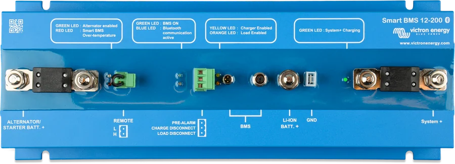
Smart BMS 12/200 seen from above
Smart BMS 12/200 and Smart BMS CL 12/100
A complete BMS for Victron Lithium Battery 12,8 V Smart batteries in vehicles and boats. It combines a current limiter, battery switch and protection: it lets you connect any size alternator safely, protects it from overload and monitors the voltage of each cell. The 12/200 version also has a 200 A System+ power port.
- 12.8 V
- up to 20 batteries
- Bluetooth
- pre-alarm
- IP65 (electronics)
Alternator and lithium battery without casualties
A lithium battery accepts current so readily that a standard car alternator runs at full load and can overheat after a few minutes. On the other hand, a discharged starter battery can ‘suck dry’ the lithium battery. Smart BMS solves both problems: it limits the input current and allows current to flow only one way — from the alternator to the lithium battery.
At the same time it performs the normal role of a BMS: it monitors the voltage and temperature of each cell and disconnects charging or loads if there is a risk. Everything is configured over Bluetooth in the VictronConnect app.
- alternator current is electronically limited to about 90% of the fuse rating,
- current flows only when the voltage at the input exceeds 13 V, and never the other way,
- up to 20 batteries can work in the system, which means as much as 84 kWh at 12 V.
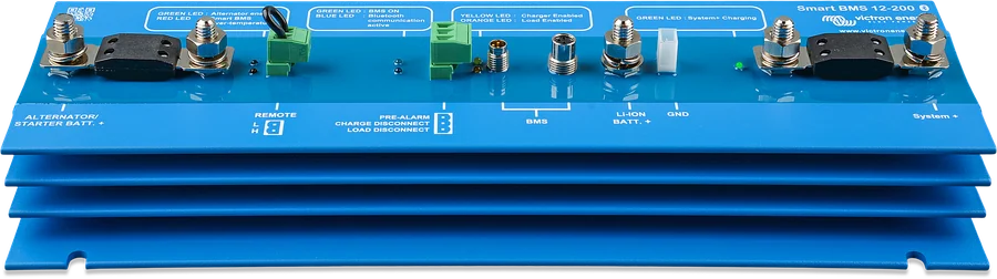

What Smart BMS does
Alternator current limiting
Input current is electronically limited to about 90% of the fuse rating. A 125 A fuse gives about 100 A, 100 A gives about 90 A, and for lower requirements a pair of ATO fuses from the kit is used.
Movement in one direction only
Current flows to the lithium battery only above 13 V at the input and does not return to the starter battery — it is protected from deep discharge.
System+ port 200 A
Only in the 12/200 version: a bidirectional power port for connecting an inverter, charger or DC loads — 200 A continuous, 400 A peak.
Cell protection
The BMS monitors each cell in the battery and disconnects the alternator, charging sources or loads if cell voltage is too low or too high, or if temperature is too high.
Pre-alarm
It warns at least 30 seconds before disconnecting the loads — with a continuous or intermittent signal, current up to 1 A (output without short-circuit protection).
Load and Charge disconnect outputs
Two 10 mA control outputs — for the remote input of BatteryProtect, inverter, DC-DC converter or charger. Normally high, they go idle when there is a fault.
Bluetooth and Instant Readout
Configuration, monitoring and diagnostics in VictronConnect. Instant Readout shows the key values plus warnings and alarms without connecting to the device.
Remote on/off
The Remote L and H terminals can be set as a switch for alternator charging only or for the whole system. A wire loop or switch between L and H is mandatory.
12/200 or CL 12/100
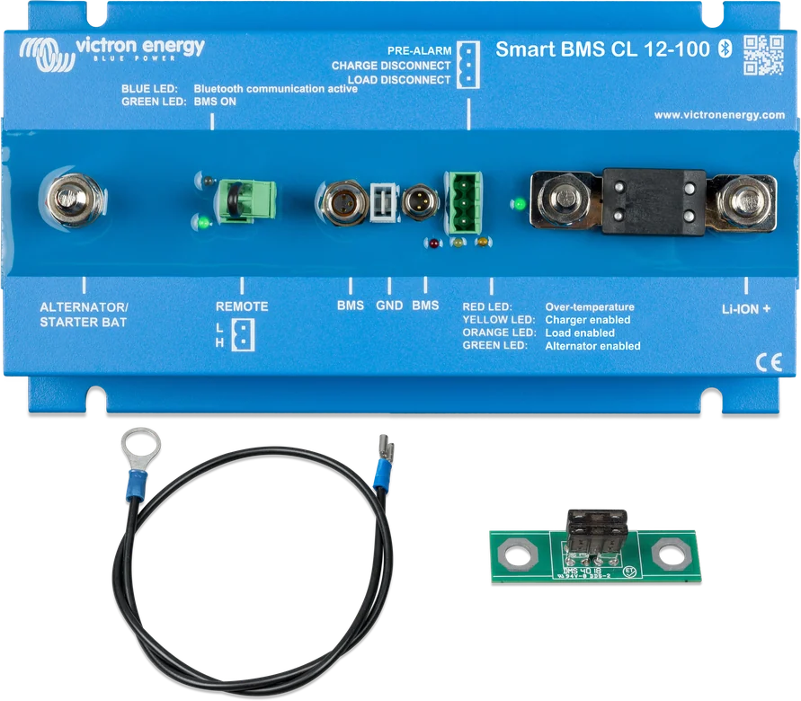
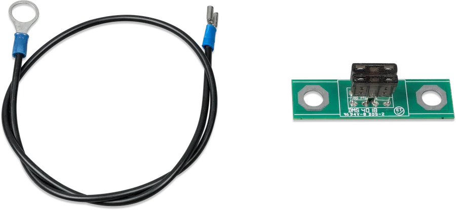
| Parameter | Smart BMS 12/200 | Smart BMS CL 12/100 |
|---|---|---|
| Alternator port — max charging current | 100 A (125 A fuse) | 100 A (125 A fuse) |
| System+ port — charging and discharging | 200 A | none |
| Peak discharge current | 400 A | — |
| Current draw, remote on | 17.5 mA | 16 mA |
| Current draw, remote off | 6.5 mA (4.5 mA with BMS off) | 5 mA |
| Weight | 2 kg | 1.6 kg |
| Dimensions (H × W × D) | 65 × 120 × 340 mm | 65 × 120 × 224 mm |
| Operating temperature | −40°C to +60°C | |
| Power connections | M8, tightening torque 10 Nm | |
Both versions support up to 20 Smart 12.8 V lithium batteries and have the same three control outputs: Load disconnect, Charge disconnect and pre-alarm.
How it is wired
The alternator and starter battery go to the Alternator/Starter Batt+ port, the lithium battery to Li-Ion+, and the inverter or loads to the System+ port. The battery communication cables are daisy-chained to the BMS port. Hover over a diagram element or tap it. Schematic diagram.
- Choose the fuseIt sets the alternator current: 125 A → 100 A, 100 A → 90 A, 60 A → 50 A.
- Connect the power terminalsStarter battery positive to Alternator/Starter Bat+, lithium positive to Li-Ion+, tightening torque 10 Nm.
- Communication cablesDaisy-chain between the batteries, ends to the BMS port; extend with 3-pin M8 cables.
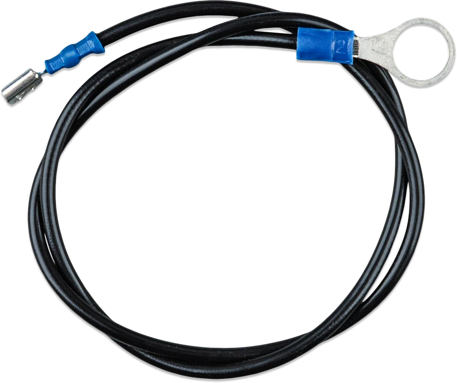
- Ground cableThe supplied GND cable also goes to the lithium negative and starter battery negative — with a 0.3–1.3 A fuse.
- Remote on/offA wire loop or switch between L and H is mandatory; otherwise the BMS will not operate.
The fuse sets the charging current
In this BMS, the alternator port fuse also acts as a shunt — its value tells the system how much current may be drawn. That is why the value set in the app must match the physical fuse fitted.
| Fuse | Maximum alternator current |
|---|---|
| 125 A | 100 A |
| 100 A | 90 A |
| 80 A | 60 A |
| 60 A | 50 A |
| 2 × 30 A (ATO) | 40 A |
| 2 × 20 A (ATO) | 25 A |
| 2 × 15 A (ATO) | 20 A |
| 2 × 10 A (ATO) | 12 A |
| 2 × 7.5 A (ATO) | 9 A |
For currents below 40 A, the manufacturer requires the supplied ATO holder with the correct pair of fuses. In VictronConnect, also set the fuse type, the pre-alarm mode (continuous or intermittent), whether the pre-alarm is present in the battery, and the voltage threshold at which charging should stop — range 13.0–15.3 V, typically 14.2 V for Victron Lithium Battery Smart. Charging resumes when the voltage stays 0.5 V below that threshold for 10 seconds.
The recommended order
Before installation, disconnect the cable from the starter battery negative and remove the remote on/off plug so the BMS does not switch on during work. The lithium and starter battery negatives are connected last.
The power connections are M8. The fuse nuts must also be tightened — a loose connection at these currents overheats and burns.
The supplied GND cable must also be protected: depending on the installation, with a 0.3 to 1.3 A fuse. The value is calculated from the BMS and output current draw — for example, 16 mA + 10 mA + 10 mA + 1 A multiplied by 1.25 gives about 1.3 A.
- Vertical surface. The manufacturer recommends mounting on a vertical wall — cooling works best there.
- Short cables. Plan the route before installation to avoid unnecessary connections and long runs at currents of around 200 A.
- PIN code. At the first pairing in VictronConnect, enter the PIN from the information sticker on the unit.
Which BMS for a lithium battery
Smart BMS 12/200
A 12 V system with an alternator and inverter. The 200 A System+ port lets you connect the inverter directly to the BMS, without extra control wiring.
alternator + power portSmart BMS CL 12/100
The same alternator current limiting, but without the System+ port. Smaller and lighter — for when you control the inverter and loads separately.
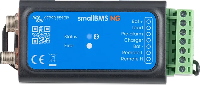
100 A alternatorsmallBMS NG
A simple BMS with the same three control outputs, without alternator current limiting. For 12, 24 and 48 V systems.
Load · Charge · pre-alarmVE.Bus BMS V2
When a MultiPlus or Quattro is the heart of the system, the BMS talks to them via VE.Bus and controls them directly.
VE.Bus · MultiPlusTypical problems
The most common mistakes with this BMS are the wrong fuse value and a forgotten remote on/off loop.
The alternator does not charge the lithium battery
Current will only flow when the voltage at the Alternator/Starter Batt+ input exceeds 13 V. Also check whether remote on/off has a wire loop fitted or the switch closed.
Charging current lower than expected
That is intended behaviour: the system limits the current to about 90% of the fuse value. A 100 A fuse gives about 90 A, 60 A gives about 50 A.
The app does not show charging current
On the first connection, you must set the fuse type in the settings menu — only then can the BMS calculate the current in percent.
Charging stops before full charge
Check the set voltage threshold (range 13.0–15.3 V, typically 14.2 V). Charging will resume when the voltage stays 0.5 V below the threshold for 10 seconds.
The BMS disconnected everything in frost or heat
This is a response to cell temperature. The BMS itself operates from −40°C to +60°C, but the lithium battery has narrower limits — especially for charging below freezing.
The pre-alarm buzzer sounds too late
The pre-alarm activates at least 30 seconds before the loads are disconnected. It can be changed from continuous to intermittent; the output provides up to 1 A and is not short-circuit protected.
After switching off remote, the BMS still draws current
With remote off, current draw is 6.5 mA (12/200) or 5 mA (CL) — the BMS functions still run. Only a full BMS shutdown reduces this to 4.5 mA.
The battery communication cables are too short
Extend them with male-female 3-pin M8 cables. Do not extend power cables without recalculating the cross-section — at 200 A, every metre counts.
Frequently asked questions about Smart BMS
Which batteries does it work with?
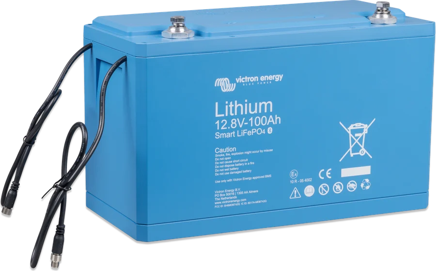
With Victron Lithium Battery 12.8 V Smart batteries — up to twenty in one system, which at 12 V gives as much as 84 kWh.
Why limit alternator current?
Because a lithium battery will take as much as the alternator can supply. Most 12 V alternators overheat and fail if they run at maximum for more than about five minutes. The BMS keeps the current at the level set by the fuse.
Which fuse should you choose?
Depending on how much current is to flow: 125 A gives about 100 A, 100 A → 90 A, 80 A → 60 A, 60 A → 50 A. Below 40 A, use the pair of ATO fuses in the supplied holder.
What is the difference between 12/200 and CL 12/100?
The 12/200 version also has a bidirectional 200 A System+ power port (400 A peak), to which you connect an inverter, charger or loads. The CL only limits alternator current and is shorter and lighter.
Can I connect a MultiPlus directly to the BMS?
Yes, in the 12/200 version — the manufacturer shows this setup: a Multi connected to the System+ port does not require control from the Charge and Load disconnect outputs, which saves wiring.
What are the Load and Charge disconnect outputs for?
For controlling the remote input of other devices: BatteryProtect, inverter, DC-DC converter, charger or Cyrix-Li relay. The load is 10 mA — they are not suitable for powering a relay coil.
Is the remote on/off loop necessary?
Yes. The manufacturer requires either a switch or a factory wire loop between terminals L and H — otherwise the BMS will not work properly.
How do you control DC loads without the System+ port?
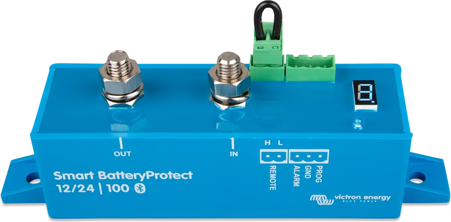
Through BatteryProtect: the BMS’s Load disconnect output then turns off the BatteryProtect output when cell voltage is too low, protecting the battery from further discharge.
Content compared with Victron Energy documentation (datasheets and manuals) — current as of 20 September 2026. Report a content error · Correction log