
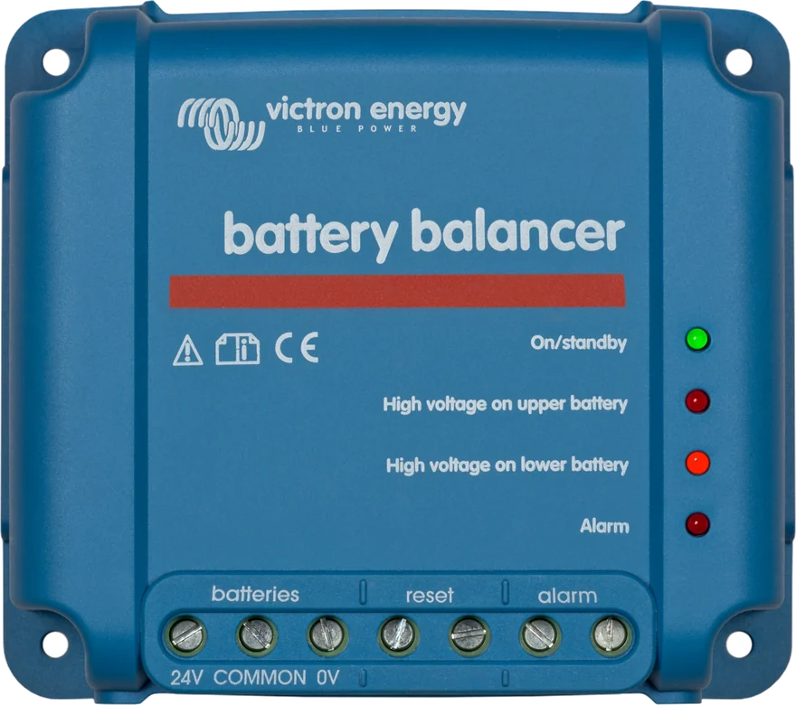
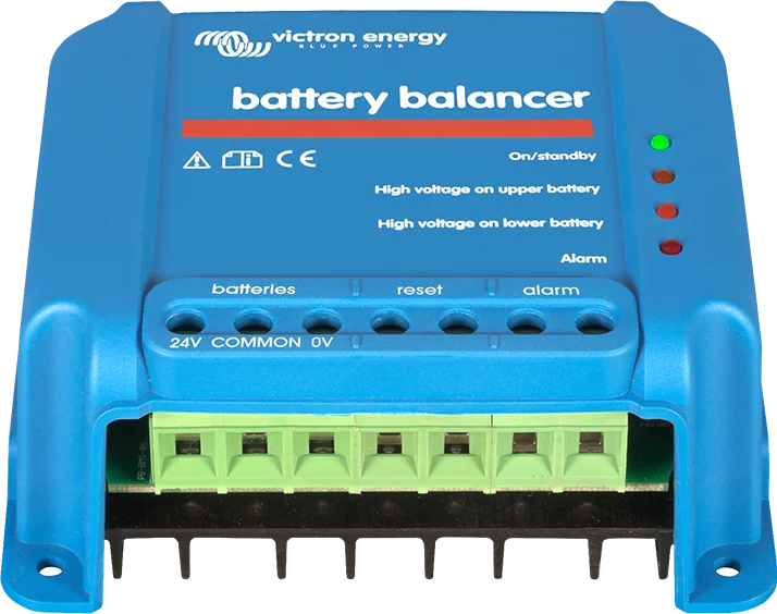
Victron Battery Balancer viewed from the front
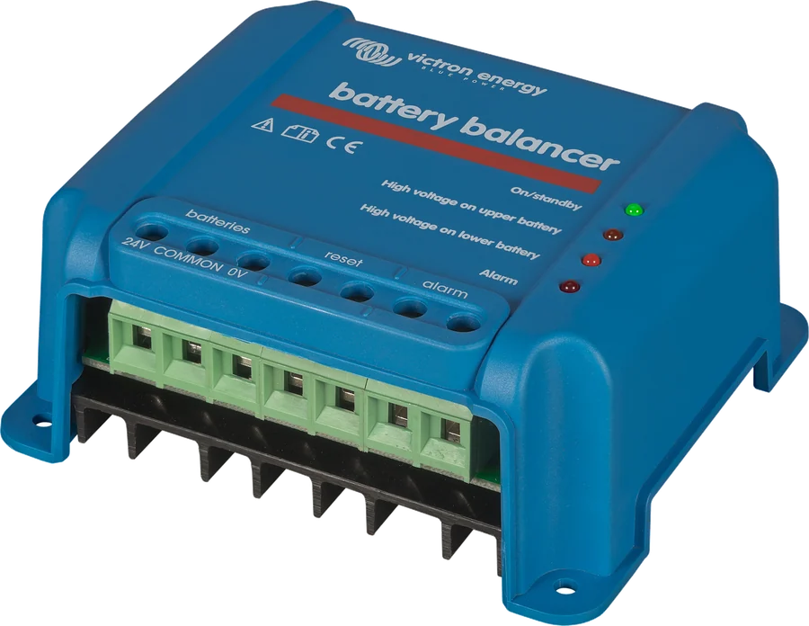
Victron Battery Balancer
In a 24 V or 48 V bank, one battery with a slightly higher leakage current is enough for the whole set to become unbalanced after a few months: one battery is constantly undercharged, the other is systematically overcharged. The balancer compares the voltages of both halves and transfers up to 0.7 A from the more charged one before the difference starts to shorten battery life.
- 24 V i 48 V
- 0.7 A
- alarm relay
- IP22
- −30 to +50°C
One weaker battery spoils the whole bank
Batteries connected in series charge with the same current, but not equally. If one has a higher leakage current, it will gradually fall behind — the charger “sees” only the total voltage, so it adds voltage to the others. The result: one battery is chronically undercharged, the other overcharged, and both have a shorter life.
The balancer measures the voltage of both batteries in the series separately and draws up to 0.7 A from the one with the higher voltage. The resulting difference in charging current brings the batteries to the same state of charge.
- it switches on only during charging, above 27.3 V on the battery pair,
- below 26.6 V it goes into standby and draws only 0.7 mA,
- at a difference above 200 mV it lights the red LED and closes the alarm relay.
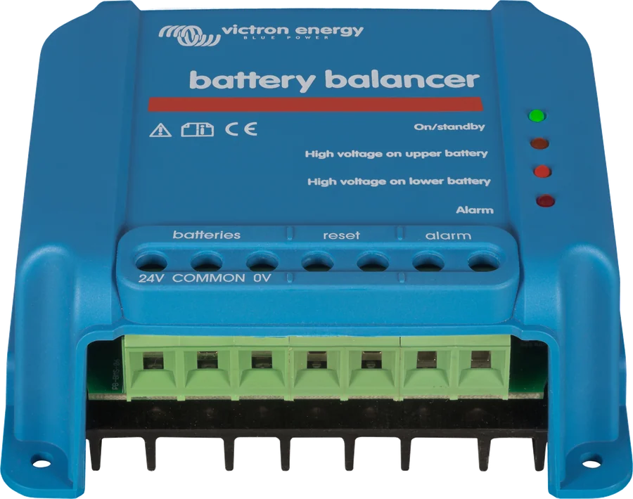
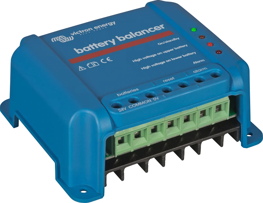
How the balancer works
0.7 A balancing
It draws up to 0.7 A from the battery with the higher voltage when the difference exceeds 100 mV. Balancing itself starts already at a 50 mV midpoint deviation.
Works only during charging
It switches on above 27.3 V on the battery pair (±1%), switches off below 26.6 V. Outside charging, it draws 0.7 mA, so it does not discharge the bank.
Four LEDs
Green — the balancer is working, two amber LEDs show which half is being balanced, red indicates an alarm.
Alarm relay
Normally open contact 60 V / 1 A, closes together with the red LED coming on. You can use it to trigger remote signalling.
Alarm reset
Two terminals for a momentary push-button. Shorting them resets the relay, but the lockout lasts only until the current alarm ends — the next one will close the contact again.
Parallel connection
Balancers can be connected in parallel. The manufacturer assumes that one unit serves on average up to three parallel branches of 200 Ah.
Thermal protection
The unit has overtemperature protection and operates in the range from −30°C to +50°C, at humidity up to 95% non-condensing.
Complements the battery monitor
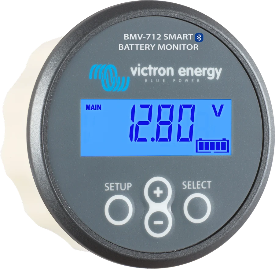
A monitor with midpoint measurement — such as the BMV-702 — shows the deviation in volts or percent and can itself trigger an alarm. The balancer further reduces this deviation.
How many balancers for which bank
| Parameter | Value |
|---|---|
| Input voltage range | up to 18 V per battery, 36 V total |
| Turn-on / turn-off threshold | 27.3 V / 26.6 V (±1%) |
| Deviation that starts balancing | 50 mV |
| Maximum balancing current | 0.7 A (at a deviation above 100 mV) |
| Alarm / alarm reset threshold | 200 mV / 140 mV |
| Alarm relay | 60 V / 1 A, normally open |
| Terminals | screw type 6 mm² (AWG10) |
| Protection rating / weight | IP22 / 0.4 kg |
| Dimensions (H × W × D) | 100 × 113 × 47 mm |
How to connect the balancer
The balancer is connected with three wires: to the bank positive, to the negative and to the midpoint between the batteries. Hover over or tap the diagram element. Schematic diagram.
- Mounting locationA vertical, ventilated surface near the batteries — but not above them.
- Alarm wiresIf you use signalling and the reset button, connect them first.
- Connection orderNegative, positive, midpoint — in that order, with cable at least 0.75 mm².
- ProtectionWhere UL requirements apply, protect all three wires with 10 A fuses near the batteries.
- CheckDuring charging above 27.3 V the green LED lights up — the balancer is working.
Where and how to mount it
The balancer is mounted on a vertical, well-ventilated surface near the batteries, but never above them — gases released by batteries are corrosive to electronics.
The wires connecting the midpoints must carry the current that will flow if one battery opens the circuit. With two parallel branches this is 50% of the series-wire cross-section, with three branches — 33%.
Negative, positive and midpoint — in that order, with cable at least 0.75 mm². Screw terminals accept up to 6 mm². Where the installation must meet UL requirements, each wire is protected near the battery with a 10 A DC automotive fuse.
- 24 V system: one balancer for two 12 V batteries in series.
- 48 V system: three balancers for four 12 V batteries in series.
- Large banks: balancers can be connected in parallel — on average one for three parallel 200 Ah strings.
Balancer, monitor or BMS
Battery Balancer
Actively equalises the state of charge of series-connected lead-acid batteries in 24 V and 48 V systems. It also raises an alarm.
0.7 A · 200 mV alarmMidpoint monitor
BMV-702 and similar models measure midpoint deviation and show it in volts or percent, but do not equalise anything.
measurement · alarmLithium BMS
In lithium batteries, cell balancing is handled by the battery electronics and the BMS — the Battery Balancer is not needed there.
LiFePO₄What to do when the alarm activates during charging
In a new bank, the alarm is usually caused by differences in the initial state of charge. If the difference between the lowest and highest battery voltage exceeds 0.9 V, the manufacturer says to stop charging and charge the batteries separately — or greatly reduce the charge current and give the bank time to equalise.
If the problem returns after a few charge and discharge cycles, the sequence of actions is:
- in a series-parallel system, disconnect the midpoint connections and measure the voltage of each midpoint during absorption — this will identify the battery that needs topping up,
- or charge and test each battery separately,
- or add more balancers in parallel — on average one for three parallel 200 Ah strings.
LEDs and states
The balancer has no display — all information is shown by four LEDs and the alarm relay.
Green LED on
The balancer is operating — the voltage across the pair of batteries has exceeded 27.3 V, so charging is in progress.
All LEDs off
The voltage across the pair of batteries has fallen below 26.6 V and the unit has entered standby. It then draws 0.7 mA.
One of the orange LEDs on
This half of the bank has the higher voltage and is being equalised. The LED lights when the deviation exceeds 100 mV.
Red LED and closed relay
The voltage difference has exceeded 200 mV. The alarm only clears when the deviation falls below 140 mV or the system voltage drops below 26.6 V.
Alarm returns after being reset
Resetting with the button only lasts until the current alarm ends — each new alarm will close the relay again. This is a sign that the bank needs checking.
Voltage difference greater than 0.9 V
Stop charging and charge the batteries separately, or greatly reduce the charge current and allow the bank to equalise.
The balancer cannot keep up with equalisation
For larger banks, add more units in parallel — one balancer serves up to three parallel 200 Ah strings on average.
The unit gets very hot
It has thermal protection, but it must be mounted on a vertical, ventilated surface. Operating range is from −30°C to +50°C.
Battery Balancer FAQs
Do I need a balancer with lithium batteries?
No. In lithium batteries, cell balancing is handled by their own electronics and BMS. The Battery Balancer is intended for series-connected lead-acid batteries.
How many balancers for a 48 V system?
Three — a 48 V bank consists of four 12 V batteries in series, and each balancer monitors one midpoint.
When does the balancer switch on at all?
When the voltage across the pair of batteries exceeds 27.3 V, that is during charging. Below 26.6 V it goes into standby and draws 0.7 mA.
What current does it equalise with?
Up to 0.7 A, with a deviation above 100 mV. The equalisation process itself starts already at a 50 mV midpoint difference.
What does the red LED mean?
A voltage difference above 200 mV. The alarm relay closes at the same time. It will go out when the deviation falls below 140 mV or the system voltage drops below 26.6 V.
Will the balancer save a worn-out battery?
No. It can reduce small differences, but if the alarm returns after a few cycles, you need to find and replace the specific battery — the manufacturer gives a method of measuring midpoints during absorption.
What cables and fuses?
Minus, plus and midpoint with cable at least 0.75 mm² (the terminals accept up to 6 mm²). Where the installation must meet UL requirements, each wire is protected near the battery with a 10 A DC fuse.
Will the balancer replace a battery monitor?
No, but it complements one well. A monitor with midpoint measurement shows the deviation in volts or percent and can itself trigger an alarm; the balancer actively reduces that deviation.
Manufacturer documentation
Content compared with Victron Energy documentation (datasheets and manuals) — current as of 20 September 2026. Report a content error · Correction log