
01First check
- Time and weather. The controller starts charging when panel voltage is 5 V higher than battery voltage, and keeps charging while it is 1 V higher. In the evening, at night and in heavy cloud, it is normal for it not to charge.
- Is the battery simply full? In float stage the charging current drops to almost zero — this is not a fault.
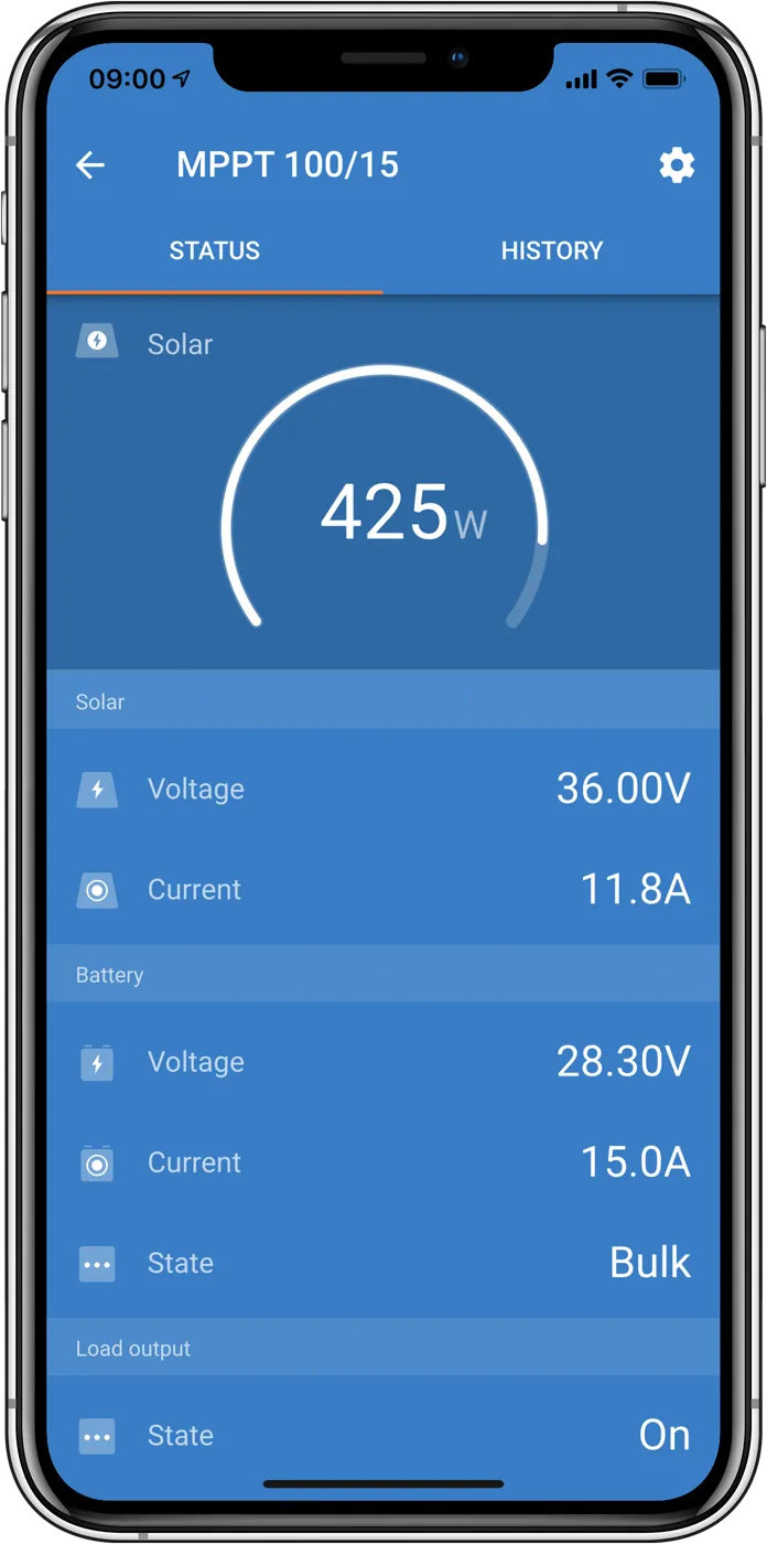
- Error code on the VictronConnect status screen. If there is one — start with the error code list.
- Visible damage: cracked enclosure, burnt or melted terminals, signs of water or corrosion. The manual states that such damage is usually not covered by the warranty.
Some controllers allow panel voltage up to 250 V. Voltage above 50 V is considered dangerous — measurements at this voltage should be carried out by a qualified technician.
02Step-by-step diagnosis
1Does the controller react at all?
The controller is “alive” when its LEDs are lit or flashing and you can connect to it in VictronConnect (Bluetooth or VE.Direct). There is no on/off switch — it turns on when it receives power from the battery, the panels, or both.
Go to step 2.
Before working on wires, fuses or switches, disconnect PV first, then the battery; when restarting, connect the battery first, then PV — an incorrect connection sequence may switch off or damage the controller or the installation. Measure the voltage at the battery terminals and at the controller PV terminals with a multimeter. If it is too low, check cable continuity, fuses and switches in the battery and PV cables. Tighten the battery, load and PV terminals to 0.75 Nm. Check the battery state of charge (if necessary with another charger) and the condition of the panel array. If the voltage is correct and the controller still does not react — it is faulty.
2Does VictronConnect show an error code?
Errors are shown on the status screen, and the latest ones in the history. The controller also signals them with an LED sequence (check the LED decoder).
Check the meaning of the code in the MPPT error codes. The most common: Err 33 (PV overvoltage), Err 38 (PV input shut-down), Err 2 (battery voltage too high), Err 67 (no connection to BMS).
Go to step 3.
3Does the app show that the controller is off (Off)?
On the status screen, tap “Why is the charger off?” — the app will explain the reason. Possible causes according to the manual:
- Panel voltage too low — night, clouds, shade, dirty panels, low sun angle in winter, poor orientation; panel fault, loose or badly crimped MC4 connectors, blown fuses, disconnected switches, incorrectly used splitters; too few panels connected in series; PV wires connected the wrong way round.
- Settings are being edited on an external display (MPPT Control) — charging will resume after you close the menu.
- Charging disabled in settings — check on the battery settings page in VictronConnect whether the charger is enabled.
- Switched off by remote or BMS (via the VE.Direct port). With lithium batteries with a BMS, this is normal: the BMS switches the controller off when the battery is full or at low temperature (below about 5 °C), and charging resumes automatically. If the shut-down is unexpected, check the RX port settings and the VE.Direct non-inverting remote on/off cable.
- Low lithium battery temperature — battery protection, not a fault. The “Low temperature cut-off” function in the controller works only in a VE.Smart network when temperature is measured by Battery Sense or a battery monitor with a sensor. Do not charge a LiFePO4 battery in frost: Victron LiFePO4 Smart accepts charging only from +5 °C to +50 °C, and for batteries from other manufacturers their datasheet gives the range. See LiFePO4 in winter.
Remove the cause shown by the app. If it is the BMS or low temperature, you usually only need to wait.
Go to step 4.
4Does the app show external control?
A battery with a BMS or an ESS system can control the controller via the GX device (DVCC) — then the system decides whether to charge and at what voltage and current. VictronConnect and GX show that the controller is externally controlled.
This is normal operation, not a fault. Look for the cause in the DVCC/ESS settings and in the battery BMS (see BMS stopped charging).
Go to step 5.
5The controller is active, but the charge current is zero or close to zero?
The app shows the correct charge voltage, but almost zero current. Check in order:
- The battery is full. Bulk is about 0–80% state of charge, absorption 80–100%, float — 100%. Note: charge voltages set too low will cause a switch to float before the battery is full.
- The battery is not connected. Without a battery, the controller may show voltage and charging phase, but current is zero. Compare the voltage at the controller terminals with the voltage at the battery terminals — a difference indicates an interruption in the path: loose wires or connections, badly crimped terminals, a blown or missing fuse, a disconnected switch, a wiring error.
- Reverse battery polarity. The red wire is not always positive — check with a meter. The controller is not protected against reverse battery connection; damage caused by this is not covered by warranty. The controller fuse often blows then — even before the fuse in the battery cable.
- Blown controller fuse. Remove it and check continuity with a meter. Before fitting a new one, check and correct battery polarity. If the new fuse blows too, the controller is probably damaged.
- Charge parameters set too low: “Battery voltage”, “Absorption voltage” and “Float voltage” set too low, or “Max charge current” set to zero or a very low value.
- Temperature compensation active. If the battery temperature is too high or the function is configured incorrectly, the charge current may be zero or close to zero; check the temperature compensation settings.
- PV voltage too high. When the maximum PV voltage is exceeded, the controller stops charging, shows error #33, and the absorption and float LEDs flash rapidly. Charging resumes when the PV voltage drops 5 V below the maximum. Check the highest daily panel voltage (Vmax) in the history. Panel open-circuit voltage (Voc) rises when temperature falls below 25 °C — by the percentage per degree given by the Voc temperature coefficient in the panel datasheet. With Victron BlueSolar panels (−0.35%/°C), at −20 °C this is about 16% more than in the datasheet. Victron recommends leaving at least 10% voltage margin, and in a cold climate recalculating Voc for the lowest expected temperature. Exceeding the voltage may damage the controller, and the damage is not covered by warranty — recalculate the array in the MPPT calculator.
- Reverse panel polarity. The PV input is protected (when the installation complies with the specification) and no error appears. Symptoms: zero charge current, the controller gets very hot, PV voltage close to zero. Check with a meter that the panel positive is on the PV+ terminal.
Remove it. In case of reverse polarity and a blown fuse, proceed as above.
Go to step 6.
6Does the battery end the day undercharged?
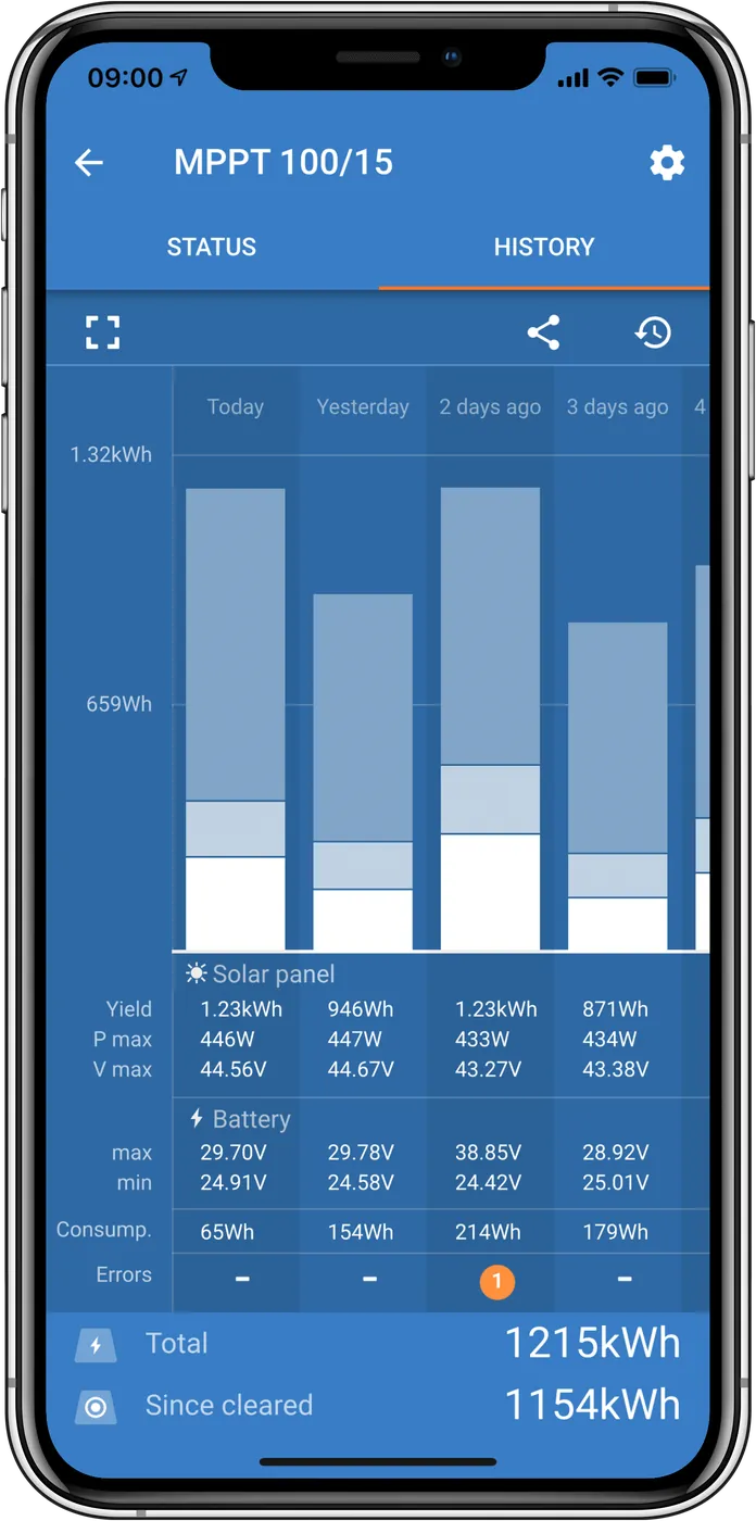
- Not enough energy from the sun. In the VictronConnect history tab, check whether the controller reaches float every day (the chart shows time in bulk, absorption and float over the last 30 days). If not, the panel array is too small, the load is too high, or the array produces less than it should (step 7). This does not apply to ESS systems — when the grid is connected, they are continuously in bulk.
- DC load too high. The battery charges only when the power from the panels is greater than the consumption of the loads (including the inverter). Compare the current from the controller with the load current — ideally with a battery monitor or current clamps.
- Voltage drop in the battery cables. The controller provides the correct voltage, but the battery receives less. Victron recommends that the voltage drop in DC cables should not exceed 2.5% (12 V: 0.3 V, 24 V: 0.6 V, 48 V: 1.2 V). Check this at full charge current: compare the voltage at the controller terminals with the voltage at the battery terminals. Causes: cables too thin, badly crimped terminals, loose connections, a loose or faulty fuse. A small drop can be compensated for by the VE.Smart network (Smart Battery Sense or a battery monitor sends the battery voltage to the controller). A large drop must be removed in the wiring. You can calculate cable cross-sections in the cable calculator.
- Temperature compensation set incorrectly. This usually applies only to lead-acid batteries — take the coefficient from the battery documentation. For lithium batteries, turn off temperature compensation.
- Different temperature of the controller and the battery. Without battery temperature data, the controller compensates the voltage according to the ambient temperature around itself. If it is, for example, by a sunny window and the battery is on a cold floor in the shade, the charge voltage will be incorrect. Provide similar conditions or pass the battery temperature via VE.Smart.
- Charge voltage or charge current set too low — as in step 5.
Correct the wiring or settings, or increase the panel array — you can calculate the balance in the energy balance calculator.
Go to step 7.
7Does the controller not reach full power?
- Power depends on battery voltage. The output current is limited to the rated current, so for example a 75/15 controller will deliver about 180 W to a 12 V battery (15 A × 12 V), and about 360 W to a 24 V battery — even with a 360 W panel.
- The panel array is too small or does not deliver full power: low sun angle, clouds, shade, dirt, poor orientation, damaged panels, problems with cables, fuses and branch connectors. Compare the daily maximum power (Pmax) in the history with the panel power.
- Different panels in one array — the manual recommends panels of the same brand, type and model.
- Optimisers — do not use them with an MPPT solar charge controller: they interfere with its algorithm and, in the worst case, can permanently damage it.
- Controller temperature above 40 °C — full power is available up to 40 °C; above that, power is reduced (operation up to 60 °C). Mount vertically, terminals facing down, with good ventilation.
- Scorched or melted PV connectors — usually due to loose screws, stiff cables, or poorly crimped MC4s; not covered by warranty.
8Reverse problem: is the battery overcharged?
Overcharging is dangerous — it can cause a battery explosion, fire, or electrolyte leakage. Do not smoke, do not create sparks, and do not use an open flame in the same room as the batteries. Causes according to the manual: the “Battery voltage” setting is too high (for example, the controller was moved from a 24 V system to a 12 V one — automatic detection only works on first startup), absorption and float voltages are too high for the battery manufacturer’s recommendations, equalising a battery that does not tolerate it (sealed and lithium batteries should not be equalised), a battery that is too small being charged with a significantly too high current, an old or damaged battery with a failed cell.
03When it is a hardware fault

According to the manual, the controller is probably faulty if it does not respond despite correct battery or panel voltage at the terminals, if a new fuse blows again, or if the error code points to an internal fault. For repair or replacement, contact the dealer or installer from whom you bought the controller. Have the model, serial number, firmware version and screenshots from VictronConnect ready.
Devices this applies to
 SmartSolar MPPT 75/10–100/20Small solar controllers with Bluetooth for campervans, boats and cabins.
 SmartSolar MPPT 150 and 250 V35–100 A controllers for higher panel voltages: 150 V and 250 V, Tr, MC4 and VE.Can versions.
 Smart Battery SenseWireless battery voltage and temperature sensor for controllers and chargers via VE.Smart.
 LiFePO4 Smart 12,8/25,6 VLithium iron phosphate batteries with Bluetooth — work only with an external BMS.
 Cerbo GXSystem control centre and gateway to the VRM portal.