
01First check
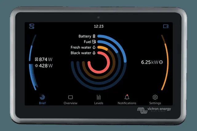
- Whether the device has power and is working — LEDs are lit, it connects in VictronConnect.
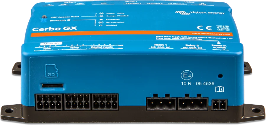
- Whether the cable is in the correct port — the manual warns not to confuse VE.Bus ports with Ethernet and VE.Can/BMS-Can ports (all have RJ45 sockets).
- Whether the GX device and the connected device firmware are up to date.
- GX error codes — for example #48 (DVCC with incompatible firmware), #49 (no grid meter found in ESS), #42 and #47 (corrupted memory — to be repaired by the seller).
02By connection type
1VE.Direct (MPPT, SmartShunt, BMV, Orion XS, Smart IP43 chargers)
- Use a VE.Direct cable (straight or angled). The maximum length is 10 m and the cable cannot be extended — for longer distances use a VE.Direct–USB interface with an active USB extender.
- If there are more devices than ports, use VE.Direct–USB interfaces, if necessary with a USB hub. Cerbo GX supports up to 15 VE.Direct devices in total, but in complex systems the limit may be lower; leave headroom when designing.
- Older controllers (for example MPPT 70/15) work with the GX only from production week 08 in 2013 (serial number from HQ1308…). A firmware update will not change this.
- The VE.Direct–VE.Can interface works only with BMV-700 and BMV-702 — not with BMV-712, MPPT controllers or VE.Direct inverters. The manufacturer does not recommend it in new installations.
- The Orion XS manual also advises checking in VictronConnect whether the TX port function is set to “Normal communication”, and whether the port itself has bent pins, and trying another cable.
2VE.Can (MPPT VE.Can, Lynx Smart BMS, Lynx Shunt, Skylla)
- Connect using a standard RJ45 UTP cable. The VE.Can network must have terminators at both ends — two are supplied with each VE.Can device.
- VE.Can devices power the network themselves; protocol converters (for example the VE.Bus–VE.Can interface) do not power it.
- The MPPT 150/70 works with the GX from firmware v2.00.
- Port: on the original Cerbo GX, Victron VE.Can devices are connected to the VE.Can port. The BMS-Can port has a fixed speed of 500 kbit/s and is used to connect batteries with third-party BMSs (for example BYD, Pylontech). On the Cerbo GX MK2 both ports are configurable (factory default VE.Can, 250 kbit/s) — check the setting in Settings → Connectivity.
- VE.Can and BMS-Can cannot be on the same bus. If both are needed, you must use a GX device with two separate CAN buses (for example Cerbo GX MK2, Ekrano GX).
3Battery with a third-party BMS (CAN-bus)
Connect to the BMS-Can port (on Cerbo GX MK2 — the port set to BMS-Can 500 kbit/s or CAN-bus BMS 250 kbit/s, depending on the battery). Fit the terminator on the GX side, and on the battery side according to the manufacturer’s instructions. The connection method and required cable are specified by the battery manufacturer and Victron compatibility documentation. Use only batteries listed in Victron’s compatibility list, as others are not supported.
4VE.Bus (MultiPlus, Quattro, VE.Bus inverters)
- RJ45 UTP cable to any VE.Bus port on the GX device; in a parallel or three-phase system — to the first or last device in the chain.
- Do not plug blue VE.Can terminators into unused VE.Bus ports — leave them empty.
- The oldest supported VE.Bus firmware is 111; devices with an 18xxxxxx microprocessor do not work with GX.
- “Multi” appears in the menu instead of the device name — the VE.Bus system, together with communication, was switched off when the GX restarted. Switch it on (Switch = On in the Multi menu or with the switch on the Digital Multi Control panel).
- “Multi” appears in the menu even though there is none — the GX remembers a previously detected VE.Bus BMS or Digital Multi Control. Run “Redetect system” in the menu, then restart the GX after one minute (Settings → General → Reboot).
- MultiPlus does not start when the GX is connected — if the GX is powered by a power supply connected to the inverter AC output, switching the system off can cause a deadlock: the inverter waits for the GX, and the GX has no power. Unplug the VE.Bus cable from the GX briefly — the inverter will start immediately. To prevent this, power the GX directly from the battery; alternatively, you can remove pin 7 from the VE.Bus cable plug on the GX side (the inverter then starts independently of the GX), but in that case the GX does not fully switch the VE.Bus device off. In marine and automotive systems, the manufacturer recommends not removing pin 7 and powering the GX directly from the battery.
5Are there devices listed that no longer exist?
The GX remembers detected VE.Bus devices. For the “Multi” entry, “Redetect system” and a restart help (step 4).
Devices this applies to
 Cerbo GXSystem control centre and gateway to the VRM portal.
 Ekrano GXGX centre with built-in 7″ touchscreen.
 SmartSolar MPPT 75/10–100/20Small solar controllers with Bluetooth for campervans, boats and cabins.
 SmartShuntBattery monitor with 300–2000 A shunt, read on your phone or on a GX device.
 Orion XSDC-DC charger 50/70 A from the alternator, including with a smart alternator.
 MultiPlusInverter/charger 800 VA–20 kW: PowerAssist, UPS under 20 ms, parallel and three-phase operation.
 Lynx Smart BMS / NGBMS with contactor and current measurement for Smart LiFePO4 or Lithium NG banks.
 Smart IP43 ChargerFixed 230 V charger up to 50 A, fanless, with VE.Direct, relay and power supply mode.
What next
The first start-up of Cerbo GX and VRM is described step by step on the Cerbo GX page. If the device shows an error code, check it in the error codes. The devices are visible, but the portal is not receiving data? See “VRM does not show data”.